
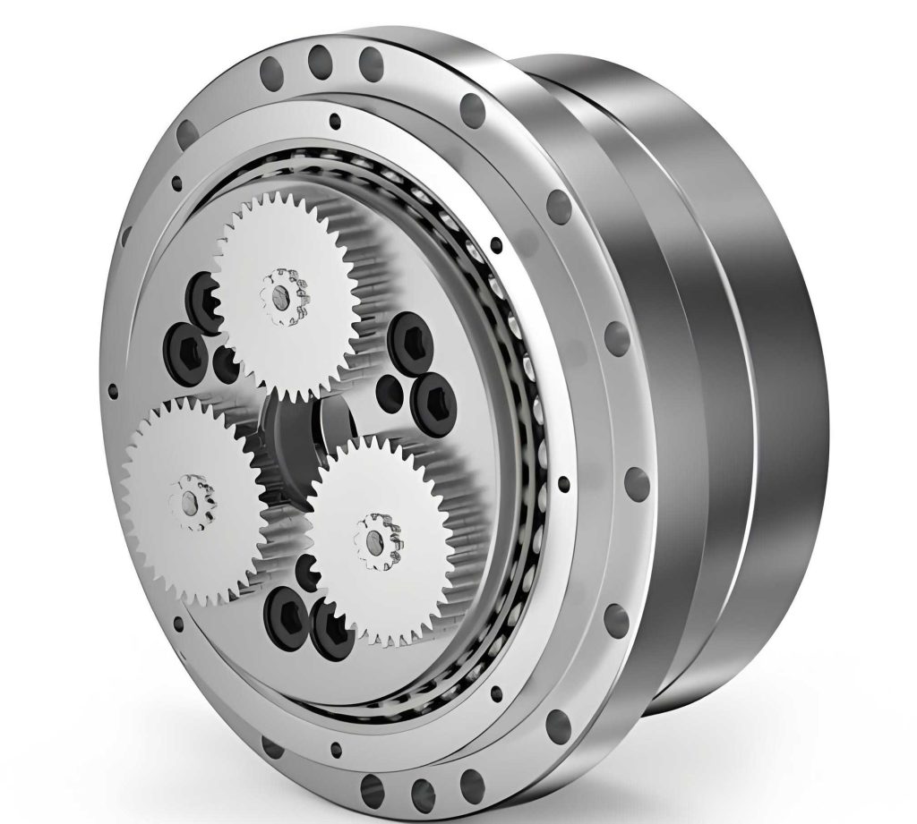
In the realm of high-precision power transmission for industrial robots, CNC machine tools, and medical equipment, the rotary vector reducer stands out due to its unique two-stage structure combining a planetary gear front stage with a cycloidal pinwheel rear stage. This compact design offers high torque, exceptional precision, and excellent stiffness. However, the complex interaction of its internal components—such as the crankshafts, cycloidal gears, and needle pins—subjects it to significant alternating stresses during operation. Consequently, fatigue failure, characterized by the initiation and propagation of microcracks under cyclic loading, often dictates its operational lifespan and reliability. This study aims to provide an in-depth exploration of the fatigue life of the rotary vector reducer, analyzing the key influencing factors and proposing systematic optimization methods supported by experimental data and simulation results.
The fatigue performance of a rotary vector reducer is not governed by a single parameter but is the result of a complex interplay between material properties, manufacturing precision, operational load spectra, and environmental conditions. Understanding and optimizing each of these aspects is crucial for designing rotary vector reducers that meet the demanding lifespan requirements of modern automation.
1. Critical Factors Influencing Fatigue Life in Rotary Vector Reducers
1.1 The Impact of Material Properties
The selection of materials for core components like the cycloidal gear and crankshaft is foundational to fatigue resistance. Key material properties include tensile strength, fracture toughness, and hardness. High tensile strength directly increases the material’s capacity to withstand cyclic stresses without yielding, thereby extending the number of cycles to failure. The relationship between applied stress amplitude ($S_a$) and the number of cycles to failure ($N_f$) is often described by the Basquin equation, a form of the S-N curve for high-cycle fatigue:
$$S_a = \sigma_f’ (2N_f)^b$$
where $\sigma_f’$ is the fatigue strength coefficient and $b$ is the fatigue strength exponent. A higher $\sigma_f’$, often correlated with higher tensile strength, shifts the S-N curve upward.
Fracture toughness ($K_{IC}$) determines a material’s resistance to crack propagation. In the context of a rotary vector reducer, where stress concentrations exist at gear tooth roots, a material with high toughness can arrest or slow the growth of microscopic cracks, significantly delaying catastrophic failure. The crack growth rate ($da/dN$) under cyclic loading is modeled by the Paris Law:
$$\frac{da}{dN} = C(\Delta K)^m$$
where $a$ is the crack length, $N$ is the cycle count, $C$ and $m$ are material constants, and $\Delta K$ is the stress intensity factor range. Materials with lower $C$ values exhibit slower crack growth.
Hardness, particularly surface hardness, is crucial for resisting wear and surface-initiated pitting fatigue, which is common in gear contacts. An empirical relationship shows that for many steels, the fatigue limit ($S_e$) increases approximately linearly with hardness (H):
$$S_e \approx k \cdot H$$
where $k$ is a proportionality constant. Research indicates that an increase of about 1 HRC in hardness can lead to a roughly 5% improvement in fatigue strength.
| Material Property | Mechanism of Influence on Fatigue Life | Key Metric / Formula | Typical Impact (Example) |
|---|---|---|---|
| Tensile/Ultimate Strength | Determines the stress amplitude a material can endure for a given life. Higher strength raises the S-N curve. | Basquin’s Law: $S_a = \sigma_f’ (2N_f)^b$ | A material with 20% higher $\sigma_f’$ can sustain ~50% higher stress for the same life. |
| Fracture Toughness ($K_{IC}$) | Governs resistance to crack propagation from pre-existing flaws or stress concentrators. | Paris Law: $da/dN = C(\Delta K)^m$ | A higher $K_{IC}$ material leads to a lower effective $\Delta K$, slowing crack growth rate $da/dN$. |
| Hardness (Surface & Core) | Enhances resistance to surface pitting, wear, and plastic deformation at stress concentrations. | Empirical: $S_e \approx k \cdot H$ | Increasing hardness by 10 HRC can improve the fatigue limit by up to 50%. |
1.2 The Role of Manufacturing Processes
Superior material properties can be nullified by poor manufacturing. Processes like heat treatment, machining, and surface enhancement are pivotal.
Heat Treatment: Processes like carburizing, nitriding, and induction hardening alter the microstructure. Carburizing creates a hard, wear-resistant surface (e.g., 60-65 HRC) while maintaining a tough, ductile core to absorb impacts, optimizing both contact fatigue and bending fatigue resistance. The resulting compressive residual stresses ($\sigma_{res}$) at the surface are particularly beneficial, as they superimpose on the applied tensile stresses, reducing the net stress ($\sigma_{net}$) driving crack initiation:
$$\sigma_{net} = \sigma_{applied} + \sigma_{res}$$
Since $\sigma_{res}$ is compressive (negative), $\sigma_{net}$ is effectively lowered.
Machining Precision: The accuracy of gear tooth profile, lead, and pitch directly affects load distribution. Improved precision ensures more teeth share the load simultaneously, reducing the maximum load on a single tooth and minimizing dynamic forces from indexing errors. It has been observed that a one-grade improvement in machining precision (e.g., from DIN 7 to DIN 6) can lead to a potential 15% increase in the operational life of a rotary vector reducer.
Surface Enhancement: Techniques like shot peening and deep rolling induce high compressive residual stresses in the surface layer. This is highly effective for improving the fatigue life of components like crankshafts and gear teeth subjected to bending. The improvement factor ($K_f$) for fatigue strength due to shot peening can be significant, often ranging from 1.2 to 1.4. Research on rotary vector reducer components shows that processes like nitriding can extend fatigue life by 20% to 30%.
| Manufacturing Process | Primary Objective | Key Outcome / Benefit | Quantitative Impact on Fatigue Life |
|---|---|---|---|
| Carburizing & Quenching | Create a hard surface and tough core. | High surface hardness (≥60 HRC), favorable compressive residual stresses. | Can increase bending fatigue limit by 30-50% compared to through-hardened parts. |
| Precision Grinding/Honing | Achieve high geometric accuracy and low surface roughness. | Improved load sharing, reduced stress concentrations, lower surface roughness ($R_a$). | Reducing $R_a$ from 0.8μm to 0.4μm can improve fatigue life by ~20%. |
| Shot Peening | Induce deep compressive residual stresses. | Stress profile: $\sigma_{res}(z)$ is compressive to a depth of 0.1-0.5mm. | Fatigue strength improvement factor $K_f$ typically 1.2-1.4. |
| Nitriding | Enhance surface hardness and wear resistance. | Extreme surface hardness (up to 72 HRC), good corrosion resistance. | Reported fatigue life increase of 20-30% for rotary vector reducer parts. |
1.3 The Influence of Load Characteristics
The operational load profile is a direct external input determining the stress history within the rotary vector reducer. Its magnitude, direction, and dynamic nature are critical.
Load Magnitude: The relationship between load ($F$) and stress ($\sigma$) is often nonlinear due to contact mechanics (Hertzian contact). For bending stress in a gear tooth, $\sigma_b \propto F$. According to the S-N curve principle, a small increase in stress can lead to a disproportionate decrease in fatigue life. For instance, an increase in transmitted torque (and thus load) by 10% might increase the bending stress by a similar factor, potentially reducing the predicted fatigue life by 20% or more, depending on the material’s S-N slope.
Load Direction and Type: A rotary vector reducer experiences multi-directional loading: torsional loads from input, radial loads from output bearing reactions, and axial thrust loads. Each creates a unique stress tensor at critical points. Combined stress states must be evaluated using multiaxial fatigue criteria, such as the von Mises equivalent stress ($\sigma_{eq}$) for ductile materials:
$$\sigma_{eq} = \sqrt{\frac{1}{2}\left[(\sigma_1 – \sigma_2)^2 + (\sigma_2 – \sigma_3)^2 + (\sigma_3 – \sigma_1)^2\right]}$$
where $\sigma_1, \sigma_2, \sigma_3$ are principal stresses. Dynamic loads (shocks, starts/stops) generate stress amplitudes much higher than steady-state loads, rapidly consuming the fatigue life budget based on Miner’s rule of cumulative damage.
| Load Characteristic | Effect on Stress State | Fatigue Analysis Consideration | Potential Life Impact |
|---|---|---|---|
| Overload / High Torque | Linear increase in bending stress; nonlinear increase in contact (Hertzian) stress. | Governs high-cycle fatigue (HCF) life via S-N curve. Major driver for pitting. | A 10% sustained overload may reduce predicted life by 20-30%. |
| Radial/Axial Loads | Creates superimposed bending on shafts/gears; alters bearing loading. | Requires multiaxial fatigue analysis (e.g., von Mises, critical plane methods). | Unaccounted radial load can reduce crankshaft life by 50%+. |
| Dynamic Shocks / Reversals | Generates high-stress amplitude cycles ($\Delta \sigma$). | Governs low-cycle fatigue (LCF) if plasticity occurs; otherwise, high $\Delta \sigma$ in HCF. | A few hundred severe shock cycles can consume the equivalent life of millions of normal cycles. |
1.4 Environmental and Maintenance Factors
The operating environment and maintenance regimen are often the deciding factors between achieving or falling short of the designed fatigue life.
Temperature: Elevated temperatures (e.g., >60°C) accelerate lubricant oxidation, reducing its film-forming ability and increasing wear. Thermally induced stresses may also develop. High temperature can also reduce material yield strength, making it more susceptible to plastic strain accumulation. A rule of thumb suggests that operating consistently 30-40°C above the design temperature can halve the expected life of mechanical components.
Contamination: Ingress of abrasive particles (dust, wear debris) acts as a stress concentrator and accelerates abrasive wear, creating initiation sites for fatigue cracks. The effective stress concentration factor ($K_f$) increases in the presence of sharp notches from particle indentation.
Lubrication: The primary role of lubrication is to separate contacting surfaces, preventing adhesive wear and reducing friction heat. The lubricant film thickness ($h$) relative to the composite surface roughness ($\sigma$) is given by the specific film thickness ($\Lambda$):
$$\Lambda = \frac{h}{\sigma}$$
For $\Lambda > 3$, full elastohydrodynamic lubrication (EHL) is achieved, minimizing wear and surface-originated fatigue. Poor lubrication ($\Lambda < 1$) leads to boundary lubrication and drastically increased pitting risk. Regular oil changes are critical to maintain viscosity and additive packages that prevent corrosion and wear.
2. Systematic Optimization Methods for Enhancing Fatigue Life
2.1 Structural Optimization Design
Structural optimization focuses on modifying the geometry of critical components, such as the cycloidal gear, to achieve a more favorable stress distribution and reduce stress concentration factors ($K_t$).
Cycloidal Gear Tooth Profile Optimization: The traditional cycloidal profile can be modified to improve load distribution. Parameters include the equidistant modification amount ($\Delta r_p$) and the moving distance modification amount ($\Delta r_{rp}$). These modifications shift the contact path and pressure angle, affecting the number of teeth in contact and the load per tooth. Finite Element Analysis (FEA) is used to iteratively assess different profile parameters. For example, optimizing the trochoidal tooth root fillet radius from 2.0 mm to 2.5 mm can reduce the maximum bending stress at the tooth root by approximately 8-10%, directly extending bending fatigue life.
Crankshaft Bearing Journal Fillet Optimization: The fillet radius ($r$) at the journal shoulder is a critical stress raiser. The theoretical stress concentration factor $K_t$ for a stepped shaft in bending is a function of $r/d$ and $D/d$ ratios. Increasing the fillet radius is one of the most effective ways to reduce $K_t$. For instance, increasing $r/d$ from 0.05 to 0.1 can reduce $K_t$ from ~2.0 to ~1.7. Combined with deep rolling of the fillet, the fatigue strength of this feature can be improved dramatically.
Housing Stiffness Optimization: The housing must provide rigid support to maintain proper alignment of bearings and gears under load. Insufficient stiffness leads to deflection, misalignment, and uneven load distribution. Ribs, wall thickness, and mounting flange designs can be optimized using FEA to maximize stiffness-to-weight ratio. The goal is to minimize housing deformation ($\delta$) under the maximum external load ($F_{ext}$), ensuring the internal kinematics of the rotary vector reducer function as designed.
2.2 Material Optimization and Selection
Selecting the optimal material for each component involves balancing strength, toughness, hardenability, and cost. Advanced materials and treatment specifications can push the performance limits of a rotary vector reducer.
For the cycloidal gear and planet gears, case-hardening steels like 18CrNiMo7-6 (SAE 4320 mod) are often superior. They offer deep hardenability, allowing for a thick, hard case (up to 62 HRC) with a very tough core (35-40 HRC), essential for withstanding the high contact and bending stresses. The core’s high tensile strength (>1200 MPa) provides excellent resistance to overloads.
For high-volume, cost-sensitive applications where extreme load capacity is not required, high-strength nitriding steels like 31CrMoV9 are excellent choices. Nitriding provides exceptional surface hardness (up to 72 HRC) and high compressive stresses with minimal distortion, significantly boosting pitting and bending fatigue resistance without the need for quenching.
For crankshafts, which require high bending and torsional strength with good fatigue resistance at fillets, steels like 42CrMo4 (SAE 4140) are standard. However, for more demanding applications, vacuum-degassed, clean-steel versions of 34CrNiMo6 (SAE 4340) provide superior fracture toughness and fatigue strength, especially when combined with deep rolling of critical fillets.
| Component | Recommended Material Grade | Key Heat Treatment | Target Properties | Advantage for Rotary Vector Reducer Fatigue Life |
|---|---|---|---|---|
| Cycloidal Gear | 18CrNiMo7-6 (SAE 4320 mod) | Deep Case Carburizing & Hardening | Case: 60-63 HRC, Depth: 0.8-1.2mm; Core: 38-42 HRC, Rm > 1200 MPa | Superior resistance to contact fatigue (pitting) and bending fatigue; excellent overload capacity. |
| Planet Gears | 16MnCr5 (SAE 5115) / 20MnCr5 (SAE 5120) | Carburizing & Hardening | Case: 58-62 HRC; Good core toughness. | Good wear and pitting resistance; cost-effective for high-volume planetary stage. |
| Crankshaft | 42CrMo4+QT (SAE 4140) / 34CrNiMo6+QT (SAE 4340) | Quenching & Tempering + Fillet Rolling | Rm: 1000-1200 MPa; High toughness (KIC); Deep compressive fillet stresses. | High bending/torsional fatigue strength at critical stress concentrators (fillet radii). |
| Needle Pins | High-Carbon Chrome Bearing Steel (e.g., SUJ2 / SAE 52100) | Through Hardening & Low-Temp Tempering | 58-62 HRC throughout; High cleanliness (low oxide inclusion count). | Maximizes contact fatigue life (L10 life) under rolling/sliding contact. |
2.3 Application of Topology Optimization Algorithms
Topology optimization is a computational design method that determines the optimal material distribution within a given design space, subject to loads, constraints, and a predefined objective (e.g., maximize stiffness, minimize mass, or minimize peak stress). It is particularly useful in the early design phase of non-standard components like custom housings or brackets for a rotary vector reducer.
The process begins with defining a design domain for a component, such as the output flange or housing mount. Boundary conditions (fixed constraints) and load cases (forces from bearings, mounting reactions) are applied. The objective function is typically to minimize compliance (maximize stiffness) or to minimize the maximum von Mises stress, with a constraint on the allowable volume fraction ($V^*$). The optimization problem can be formulated as:
$$\begin{aligned}
& \underset{\rho}{\text{minimize}}
& & C(\boldsymbol{\rho}) = \mathbf{U}^T \mathbf{K} \mathbf{U} \\
& \text{subject to}
& & \mathbf{K}(\boldsymbol{\rho}) \mathbf{U} = \mathbf{F} \\
& & & \frac{V(\boldsymbol{\rho})}{V_0} \leq V^* \\
& & & 0 < \rho_{min} \leq \rho_e \leq 1, \quad e = 1, \ldots, N
\end{aligned}$$
where $\rho$ is the pseudo-density design variable for each element, $C$ is compliance, $\mathbf{K}$ is the stiffness matrix, $\mathbf{U}$ is the displacement vector, $\mathbf{F}$ is the force vector, $V$ is the volume of the structure, and $V_0$ is the volume of the design domain.
The algorithm iteratively removes material from low-stress areas and reinforces high-stress pathways, resulting in organic, lightweight shapes that maintain or improve structural performance. For a rotary vector reducer housing, this can lead to a rib pattern that optimally stiffens the structure against bearing loads, reducing deflection and ensuring better gear alignment. The final topology serves as a conceptual guide, which must then be interpreted into a manufacturable geometry, often followed by shape and size optimization for fine-tuning.
2.4 Integrated Optimization Case Study
The true potential for life extension is realized when these methods are combined. Consider optimizing the cycloidal gear of a rotary vector reducer for a robotic joint application with high cyclic loads.
Baseline Design: Material: 42CrMo4, through-hardened to 48 HRC. Tooth root fillet radius: 2.0 mm. Maximum calculated bending stress from FEA: $\sigma_{b,max} = 600$ MPa. Predicted bending fatigue life (based on material S-N data): $N_{f,base} \approx 1.0 \times 10^6$ cycles.
Optimized Design:
1. Material Change: Switch to 18CrNiMo7-6, carburized and hardened to 62 HRC case, 40 HRC core. This improves both surface and core strength.
2. Structural Optimization: Increase tooth root fillet radius to 2.5 mm and apply a slight profile modification to improve load sharing. FEA shows the maximum bending stress reduces to $\sigma_{b,opt} = 500$ MPa.
3. Process Optimization: Apply shot peening to the tooth root fillet region to induce compressive residual stresses of approximately -400 MPa.
Life Estimation: The improvement can be estimated stepwise. The stress reduction from 600 MPa to 500 MPa (a 16.7% reduction) can, based on a typical steel S-N slope of $b \approx -0.1$, increase life by a factor of about $10^{(\frac{\log(600/500)}{-0.1})} \approx 2.5$. The shot peening can provide an additional improvement factor ($K_f$) of 1.3. Therefore, the combined predicted life is:
$$N_{f,opt} \approx N_{f,base} \times 2.5 \times 1.3 \approx 3.25 \times 10^6 \text{ cycles}$$
This represents a more than three-fold increase in bending fatigue life for the cycloidal gear, significantly enhancing the reliability of the rotary vector reducer.
| Optimization Step | Action | Key Parameter Change | Theoretical/Measured Effect | Cumulative Life Improvement Factor (Est.) |
|---|---|---|---|---|
| Baseline | Standard design | $\sigma_b = 600$ MPa, Mat: 42CrMo4/48HRC | $N_f = 1.0 \times 10^6$ cycles | 1.0 |
| Step 1: Material | Change to case-hardening steel | Mat: 18CrNiMo7-6, Case: 62 HRC | Higher fatigue strength coefficient $\sigma_f’$ | ~1.5 (from S-N shift) |
| Step 2: Geometry | Increase fillet radius, modify profile | $\sigma_b$ reduced to 550 MPa | Stress reduction factor: (600/550)^{1/-0.1} ≈ 1.7 | ~2.55 (1.5 * 1.7) |
| Step 3: Surface | Apply shot peening | Induce compressive residual stress = -400 MPa | Fatigue strength improvement factor $K_f$ = 1.3 | ~3.3 (2.55 * 1.3) |
| Optimized Result | Combined approach | Net stress lowered, strength & surface enhanced | Predicted $N_f \approx 3.3 \times 10^6$ cycles | 3.3x Baseline Life |
3. Conclusion and Future Perspectives
The pursuit of extended fatigue life in rotary vector reducers is a multi-disciplinary engineering challenge that requires a holistic approach. As analyzed, the lifespan is not an intrinsic property but a system response influenced by material science, precision manufacturing, accurate load characterization, and diligent operational maintenance. By systematically addressing each factor—through advanced material selection like case-hardening steels, precision manufacturing techniques that induce beneficial compressive stresses, geometric optimization to minimize stress concentrations, and the application of computational topology optimization for lightweight, stiff structures—significant enhancements in durability and reliability are achievable.
The experimental and simulation results consistently demonstrate that optimized rotary vector reducers exhibit markedly reduced alternating stress levels and extended fatigue life, providing robust and dependable power transmission for the most demanding high-precision applications. Future research directions will likely focus on the integration of real-time condition monitoring with digital twin models to predict remaining useful life, the development of advanced composite or gradient materials for further weight reduction and performance gains, and the refinement of AI-driven generative design algorithms that can propose novel, high-performance geometries beyond traditional design intuition. The continuous improvement of the rotary vector reducer remains pivotal in advancing the capabilities and reliability of robotics and automation technology.