
The rotary vector reducer, often abbreviated as the RV reducer, is a pivotal high-performance reduction device renowned for its expansive transmission ratio range, exceptional transmission accuracy, high load-bearing capacity, and extended service life. These superior characteristics have cemented its role as a critical component in precision automation equipment, most notably within the joint actuators of industrial robots and high-precision CNC machine tools. As global manufacturing trends towards greater intelligence and precision, the performance demands on core transmission components like the rotary vector reducer have intensified. Although domestic research and development of the rotary vector reducer have progressed significantly, leading to continual improvements in the performance of domestically produced units, a discernible gap persists in comprehensive performance metrics, particularly in key technical indicators such as backlash and transmission error, when compared to advanced international counterparts. Therefore, conducting an in-depth investigation into the transmission accuracy of the cycloidal-pin wheel based rotary vector reducer holds substantial theoretical significance and practical value for advancing domestic manufacturing capabilities.
Extensive research has been devoted to understanding the precision of cycloidal drives and RV reducers. Early foundational work analyzed the kinematic accuracy of single-stage cycloidal drives and derived relationships between backlash, transmission ratio, and torque influenced by manufacturing errors. Subsequent studies in the 1990s established comprehensive mechanical models for the rotary vector reducer, employing equivalent mass-spring models to formulate mathematical frameworks for analyzing the error in the transmission mechanism. These works explored the individual and combined effects of various machining and assembly errors on overall transmission precision. Domestic scholars have also made significant contributions. Research has focused on establishing the relationship between meshing errors and transmission accuracy based on the engagement principles of the cycloidal disc and pin wheel, introducing the concept of comprehensive meshing error for evaluation. Other studies have derived methods for calculating rotational error under dynamic loading conditions, considering deformations in components like pins and crank shafts. Analyses have further examined the influence of specific errors—such as pin wheel machining errors, cycloidal disc pitch accumulation errors, eccentricity errors, and planetary gear assembly errors—on the output rotation. More recent methodologies have applied the action line increment principle and error transfer matrix theory to systematically quantify how original errors in subsystem mechanisms affect the final output angular error. Furthermore, studies have developed error distribution models encompassing numerous error sources to analyze static backlash and validated these models through dynamic simulation. However, a systematic and integrated error transfer model that fully accounts for the unique two-stage structure and kinematic coupling within a rotary vector reducer remains an area for further elaboration.
This work aims to address this by establishing a comprehensive error transfer analysis model for the industrial robot rotary vector reducer. The analysis meticulously dissects the transmission chain, considering the distinct engagement characteristics of its first-stage involute planetary gear reduction and second-stage cycloidal-pin wheel planetary reduction. The influence of original geometric errors inherent in each major component on the system’s output rotation is analyzed sequentially. Based on this analysis, a holistic error transfer model is constructed. This model explicitly delineates the mapping relationship between various original errors and the ultimate output error of the mechanism. To validate the model’s utility and accuracy, a numerical case study is performed using the parameters of an RV40E-type reducer, complemented by experimental analysis. The findings provide critical insights for the precision design and manufacturing tolerance allocation of rotary vector reducers.
Structural Composition and Operational Principles
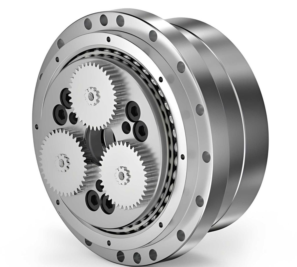
The rotary vector reducer is a compound transmission device that integrates two planetary reduction stages into a compact, coaxial configuration. Its operational principle can be broken down into the following stages:
- First-Stage Reduction (Involute Planetary Gear Transmission): External motive power is applied to the input shaft, which is connected to the sun gear. The sun gear drives multiple planet gears (typically two, arranged 180° apart for balance) that mesh simultaneously with both the sun gear and a fixed ring gear (often integrated into the housing). This planetary action results in the first level of speed reduction and torque amplification. The output of this stage is the revolution of the planet gears around the sun gear’s axis.
- Motion Transfer (Parallel Linkage Input Mechanism): Each planet gear is rigidly connected to a corresponding crankshaft (also called a cycloid generator or eccentric shaft). Therefore, the rotational motion of the planet gear is directly imparted to its crankshaft. The crankshaft features an eccentric section whose offset defines the fundamental eccentricity of the cycloidal motion.
- Second-Stage Reduction (Cycloidal-Pin Wheel Planetary Transmission): The eccentric section of each crankshaft rotates within a bearing housed in a cycloidal disc. As the crankshaft rotates, it imparts an eccentric orbital motion to the cycloidal disc. The cycloidal disc, with its lobed profile, meshes with a ring of stationary pin wheels (or pins) housed in the pin wheel casing. Due to the difference in the number of teeth between the cycloidal disc (N) and the pin wheel (N+1), the forced eccentric motion, constrained by the pins, causes the cycloidal disc to undergo a slow counter-rotation relative to the crankshaft’s direction. This is the essence of the cycloidal reduction principle.
- Final Output (Output Mechanism): The slow self-rotation of the cycloidal disc is not directly output. Instead, it is transmitted to the output flange (or output plate) via an array of pins or rollers housed in holes on the output flange, which engage with corresponding holes on the cycloidal disc. This constitutes a parallel linkage output mechanism (often a W机构 or pin-in-hole mechanism) that transmits the rotation of the cycloidal disc to the output flange with a 1:1 ratio, while canceling out its orbital eccentric motion. The output flange is directly connected to the driven load, completing the second stage of reduction.
Thus, the total reduction ratio \( i_{total} \) of the rotary vector reducer is the product of the first-stage involute ratio and the second-stage cycloidal ratio:
$$ i_{total} = i_{involute} \cdot i_{cycloidal} = \left(1 + \frac{z_r}{z_s}\right) \cdot z_p $$
where \( z_s \) is the number of sun gear teeth, \( z_r \) is the number of ring gear teeth, and \( z_p \) is the number of pins (equal to the number of cycloidal disc lobes plus one).
Foundations of the Error Analysis Model
The core methodology for quantifying the impact of individual component errors on the output angular position is based on the Action Line Increment Principle. This principle provides a systematic way to project geometric error vectors onto the kinematic chain’s constraint and motion directions.
Consider a generic pair of interacting elements, where Body 1 drives Body 3. Let \( \mathbf{n}_1 \) denote the unit vector along the direction of the constraint force (the action line) at the contact point. Let \( \mathbf{n}_2 \) denote the unit vector tangential to the instantaneous motion trajectory of a reference point on the output body (the motion line). Any geometric error \( \boldsymbol{\delta}_i \) of a component can be represented as a displacement vector.
The principle involves two sequential projections:
- Project the error vector \( \boldsymbol{\delta}_i \) onto the action line \( \mathbf{n}_1 \) to find the component that directly affects the force/motion constraint. This scalar is \( \mathbf{n}_1 \cdot \boldsymbol{\delta}_i \).
- This constraint error is then reflected onto the actual motion direction of the output. The equivalent angular or linear error \( \sigma_i \) of the output element caused by \( \boldsymbol{\delta}_i \) is given by:
$$ \sigma_i = \frac{\mathbf{n}_1 \cdot \boldsymbol{\delta}_i}{\mathbf{n}_1 \cdot \mathbf{n}_2} $$
The denominator \( \mathbf{n}_1 \cdot \mathbf{n}_2 = \cos \alpha \), where \( \alpha \) is the pressure angle between the action and motion lines, acts as an amplification/reduction factor.
This formulation allows for the aggregation of errors from multiple sources by summing their individual contributions \( \sigma_i \).
Systematic Coordinate Frame Definition
To apply the action line increment principle systematically to the multi-body system of the rotary vector reducer, a global coordinate system and local frames for each moving component are established. The global reference frame \( O_0X_0Y_0 \) is fixed at the center of the pin wheel circle, which is the axis of the final output. For each major component \( i \) (e.g., sun gear, planet gear, crankshaft, cycloidal disc, output flange), a local coordinate system \( O_iX_iY_i \) is attached to its geometric center or axis of rotation. The transformation from a local frame \( i \) to the global frame \( 0 \) is defined by a homogeneous transformation matrix \( \mathbf{C}_{0i} \), which incorporates both the rotational angle \( \theta_i \) of the component and any fixed positional offsets.
$$ \mathbf{C}_{0i} = \begin{bmatrix} \cos\theta_i & -\sin\theta_i & x_{0i} \\ \sin\theta_i & \cos\theta_i & y_{0i} \\ 0 & 0 & 1 \end{bmatrix} $$
Where \( (x_{0i}, y_{0i}) \) are the coordinates of \( O_i \) in the global frame \( O_0 \).
The original geometric errors (e.g., eccentricity, profile error) are defined as vectors \( \boldsymbol{\delta}_{ji} \) in their respective local frames. They are transformed into the global frame via \( \mathbf{C}_{0i} \boldsymbol{\delta}_{ji} \) before being projected onto the relevant action lines.
Error Transfer Modeling for Sub-mechanisms
The error propagation through the rotary vector reducer is analyzed by modeling its four constituent sub-mechanisms sequentially.
1. Involute Planetary Gear Transmission Error
Considering the meshing between the sun gear (1) and a planet gear (2) at a given input angle \( \theta_1 \), the action line \( \mathbf{n}_{11} \) is the common normal at the meshing point, which is fixed in space at the pressure angle \( \alpha \). The motion line \( \mathbf{n}_{12} \) is the common tangent at the pitch circles. For an error source \( \boldsymbol{\delta}_{1i} \) in this stage (e.g., center distance error, gear tooth error), its contribution to the planet gear’s rotational error \( \Delta \theta_1 \) is:
$$ \Delta \theta_1 = \frac{\mathbf{n}_{11} \cdot \left( \sum_{i=1}^{2} \mathbf{C}_{0i} \boldsymbol{\delta}_{1i} \cdot \frac{1}{i_{i2}} \right)}{r_2 \cos \alpha} $$
where \( r_2 \) is the pitch radius of the planet gear, and \( i_{i2} \) is the transmission ratio from component \( i \) to the planet gear’s rotation.
2. Parallel Linkage Input Mechanism Error
This mechanism transfers motion from the planet gear/crankshaft assembly to the cycloidal disc. The driving force from the crankshaft (3) acts perpendicular to its eccentric direction. Thus, the action line \( \mathbf{n}_{12} \) and the motion line \( \mathbf{n}_{22} \) for the cycloidal disc’s revolution are collinear and rotate with the crankshaft angle \( \theta_3 \) and initial phase \( \psi \). For an error \( \boldsymbol{\delta}_{2i} \) (e.g., crankshaft eccentricity error), the resulting error in the cycloidal disc’s revolution angle \( \Delta \theta_2 \) is:
$$ \Delta \theta_2 = \frac{\mathbf{n}_{12} \cdot \left( \sum_{i=1}^{2} \mathbf{C}_{0i} \boldsymbol{\delta}_{2i} \right)}{a} $$
where \( a \) is the nominal eccentricity of the crankshaft.
3. Cycloidal-Pin Wheel Transmission Error
This is the most complex sub-mechanism. The action line \( \mathbf{n}_{13} \) at a specific meshing point between a pin and the cycloidal disc (4) is along the normal to the cycloidal profile. The motion line \( \mathbf{n}_{23} \) is tangent to the path of the contact point relative to the disc’s center. Their directions vary with the crank angle and the specific pin in engagement. The error \( \Delta \theta_3 \) in the cycloidal disc’s self-rotation caused by an error \( \boldsymbol{\delta}_{3i} \) (e.g., cycloidal tooth profile error, pin position error) is:
$$ \Delta \theta_3 = \frac{\mathbf{E}_3}{r \cos \alpha_3} \left( \sum_{i=1}^{2} \mathbf{C}_{0i} \boldsymbol{\delta}_{3i} \cdot \frac{1}{i_{i4}} \right) $$
where \( \mathbf{E}_3 = \mathbf{n}_{13} / (\mathbf{n}_{13} \cdot \mathbf{n}_{23}) \), \( r \) is the magnitude of the position vector from the disc center to the contact point, \( \alpha_3 \) is the instantaneous pressure angle, and \( i_{i4} \) is the ratio to the disc’s self-rotation.
4. Output Mechanism Error
The output flange (6) is driven by tangential forces through the output pins. Therefore, the action line \( \mathbf{n}_{14} \) and motion line \( \mathbf{n}_{24} \) are both tangential to the output flange’s rotation. An error \( \boldsymbol{\delta}_{4i} \) in this stage (e.g., output pin hole position error on the flange) directly translates to an output rotation error \( \Delta \theta_4 \):
$$ \Delta \theta_4 = \frac{\mathbf{n}_{14} \cdot \left( \sum_{i=1}^{2} \mathbf{C}_{0i} \boldsymbol{\delta}_{4i} \right)}{r_6} $$
where \( r_6 \) is the radius from the flange center to the pin holes.
Synthesis of System-Level Transmission Error Model
The total output angular error \( \Delta \Theta \) of the rotary vector reducer is the superposition of errors from all sub-mechanisms, considering their respective positions in the kinematic chain. Errors from the first two stages (involute and parallel linkage) are attenuated by the second-stage reduction ratio before affecting the output, while errors from the last two stages (cycloidal and output) propagate directly.
$$ \Delta \Theta = \Delta \theta_1 \cdot \frac{1}{i_{cycloidal}} + \Delta \theta_2 \cdot \frac{1}{i_{cycloidal}} + \Delta \theta_3 + \Delta \theta_4 $$
A critical feedback effect unique to the rotary vector reducer architecture must be incorporated. The output flange is typically rigidly connected to the planet carrier (which holds the planet gear bearings). Therefore, any output error \( \Delta \Theta \) causes a corresponding small rotation \( \delta_f \) of the planet carrier frame. This rotation alters the effective center distance of the first-stage involute gears, introducing a feedback error \( \Delta \theta_{1f} \) into the planet gear’s motion. This feedback error is calculated and then fed back into the system model through the first-stage equation. The final, comprehensive system error model including feedback is:
$$ \Delta \Theta_{total} = \left( \Delta \theta_1 + \Delta \theta_{1f} \right) \cdot \frac{1}{i_{cycloidal}} + \Delta \theta_2 \cdot \frac{1}{i_{cycloidal}} + \Delta \theta_3 + \Delta \theta_4 $$
This closed-loop model more accurately represents the error dynamics of the precision rotary vector reducer.
Numerical Simulation: Case Study on an RV40E Reducer
To quantify the influence of various errors, a numerical simulation was performed using the parameters of a common model, the RV40E reducer. The key design parameters are listed in the table below.
| Parameter | Symbol | Value | Unit |
|---|---|---|---|
| Sun Gear Teeth | \( z_s \) | 9 | – |
| Planet Gear Teeth | \( z_p \) | 27 | – |
| Involute Pressure Angle | \( \alpha \) | 20 | deg |
| Cycloidal Disc Teeth | \( z_c \) | 39 | – |
| Pin Wheel Teeth (Pins) | \( z_{pw} \) | 40 | – |
| Pin Center Circle Radius | \( r_p \) | 64 | mm |
| Crankshaft Eccentricity | \( a \) | 1.25 | mm |
| Output Pin Circle Radius | \( r_6 \) | 27 | mm |
Four representative original errors, each with a magnitude of 0.005 mm (5 μm), were selected from each sub-mechanism for analysis:
- δ11: Center distance error in the involute stage.
- δ21: Crankshaft eccentricity error (deviation from nominal ‘a’).
- δ31: Cycloidal tooth profile error (normal to the profile).
- δ41: Output flange pin hole position error (radial eccentricity).
Their vector definitions in the global coordinate system are formulated accordingly.
The established error model was solved numerically for one full revolution of the output shaft. The resulting contribution of each individual error to the total output angular error (in arcseconds) is plotted and summarized.
| Error Source | Sub-Mechanism | Peak-to-Peak Effect on Output | Primary Characteristic |
|---|---|---|---|
| Output Flange Pin Hole Eccentricity (δ41) | Output Mechanism | ~35 arcseconds | Constant amplitude sinusoid, direct 1:1 transmission. |
| Cycloidal Tooth Profile Error (δ31) | Cycloidal-Pin Wheel | ~20 arcseconds | Complex periodic variation, frequency related to tooth engagement. |
| Crankshaft Eccentricity Error (δ21) | Parallel Linkage Input | ~10 arcseconds | Sinusoidal, attenuated by cycloidal ratio. |
| Involute Center Distance Error (δ11) | Involute Planetary | < 5 arcseconds | Sinusoidal, highly attenuated by total reduction ratio. |
The analysis clearly indicates that the output flange pin hole eccentricity error (δ41) has the most pronounced effect on the output angle of the rotary vector reducer. This is because this error acts directly on the final output stage without any speed reduction attenuation. The cycloidal tooth profile error (δ31) ranks second in significance, exhibiting a complex error waveform intrinsic to the cycloidal meshing kinematics. The crankshaft eccentricity error (δ21) has a moderate effect, as it is reduced by the second-stage ratio. The involute gear center distance error (δ11) has the smallest impact, being attenuated by the product of both reduction stages, highlighting that the precision of the cycloidal stage is far more critical for the overall accuracy of the rotary vector reducer.
The effect of the feedback error caused by the rigid connection between the output flange and the planet carrier was also evaluated. While its magnitude is small due to attenuation through the reduction stages, it introduces a secondary modulation to the output error. In high-precision applications, this feedback path is non-negligible and is correctly captured by the comprehensive model.
Experimental Validation and Spectral Analysis
To validate the theoretical model, a transmission error test platform was constructed for an RV40E prototype reducer. The setup consists of a servo motor drive, an input torque/speed sensor, the unit under test (the rotary vector reducer), a high-resolution output rotary encoder (grating), and a magnetic powder brake for loading. Data from the input and output sensors are acquired and processed to compute the kinematic transmission error (TE) over multiple revolutions.
The measured time-domain TE curve for the prototype exhibits a complex periodic pattern with a significant repeating component every output revolution. A Fast Fourier Transform (FFT) was applied to this signal to perform a frequency spectrum analysis, which decomposes the composite error into its constituent periodicities.
| Frequency Component | Period (in Output Rotation) | Probable Error Source Association |
|---|---|---|
| 1st Order (Fundamental, 0.00278 cycles/deg) | 360° | Assembly-related once-per-revolution error (e.g., output flange runout, bearing clearance, systematic backlash). |
| 39th Order (0.108 cycles/deg) | ~9.26° | Directly linked to the 39 teeth of the cycloidal disc. Points to cycloidal disc tooth-to-tooth errors (pitch accumulation, individual profile errors) or pin position errors. |
| Other harmonics (e.g., 2nd, 3rd, sidebands) | Various | Attributed to other periodic errors: crankshaft eccentricity (2nd order), errors in the two crank phases, output pin hole distribution errors, modulation effects from the first-stage gears (e.g., 9th order). |
The spectral analysis powerfully corroborates the theoretical findings. The dominant once-per-revolution error aligns with errors in the output mechanism and final assembly. The strong 39th order harmonic unequivocally identifies the cycloidal stage as a major contributor to transmission error variance, underscoring the critical importance of manufacturing precision for the cycloidal disc and pin wheel assembly in the rotary vector reducer. The presence of other harmonics guides further diagnostic investigation into specific component tolerances.
Conclusion and Perspectives
This work has developed a systematic, first-principles-based error transfer analysis model for the industrial robot rotary vector reducer. By applying the action line increment principle within a unified coordinate framework, the model quantitatively traces the propagation of original geometric errors from all major sub-mechanisms—the involute planetary stage, the parallel linkage input, the cycloidal-pin wheel transmission, and the output mechanism—to the final output angular error. A significant refinement includes the modeling of the kinematic feedback error arising from the fixed planet carrier-output flange connection.
The numerical case study on an RV40E-type rotary vector reducer, supported by experimental spectral analysis, yields clear hierarchical insights for precision engineering: (1) Errors in the output mechanism, particularly the radial position accuracy of the pin holes on the output flange, have the most direct and largest impact on transmission accuracy. (2) The precision of the cycloidal-pin wheel engagement (tooth profile, pitch, pin position) is the next most critical factor, generating error harmonics at the cycloidal tooth frequency. (3) Errors in the crankshaft eccentricity are moderate in effect. (4) Errors in the first-stage involute gears are greatly attenuated by the large total reduction ratio and thus have the least direct influence. Furthermore, the feedback error, though small, is a distinctive feature that must be considered in high-fidelity models for the most precise rotary vector reducer applications.
This modeling approach provides a powerful theoretical foundation for the design and tolerance allocation of rotary vector reducers. Designers can use it to perform sensitivity analyses, identifying which component tolerances require the tightest control to meet a system-level accuracy target, thereby optimizing the cost-performance trade-off. Future work will expand this model to incorporate a more exhaustive set of error sources, including pin radius errors, systematic cycloidal profile modification deviations, bearing radial play, and the effects of temperature-induced deformations. Integrating this kinematic error model with a loaded tooth contact analysis (LTCA) will further enable the prediction of dynamic transmission error and hysteresis under operational torque, providing a complete picture of the rotary vector reducer’s precision performance.