
In modern feed processing, the efficient mixing and extrusion of raw materials like soybean meal are critical for producing high-quality, digestible animal feed. The twin-screw extruder stands as a cornerstone machine in this industry due to its superior mixing, shearing, and self-cleaning capabilities. However, conventional twin-screw designs often face limitations in achieving optimal distributive and dispersive mixing, primarily due to uniform material transport and insufficient residence time in the high-shear zones. The mixing performance is intrinsically linked to the local flow patterns, shear rates, and the total time material elements are subjected to mechanical and thermal energy input within the screw channel.
To address this fundamental challenge, we present an innovative redesign of the twin-screw configuration. Our core innovation involves the strategic integration of a cycloidal drive reduction mechanism directly into the screw shaft, coupled with the implementation of a reverse-flighted screw element. The primary objective is to actively manipulate the local screw speed and flow direction to induce flow reorientation, increase shear history, and significantly enhance the mixing performance without excessively increasing the overall machine length or energy input per unit mass. This study details the parametric optimization, three-dimensional flow field analysis, and experimental validation of this novel cycloidal drive-based twin-screw extruder.
| Design Stage | Key Parameter | Symbol | Value / Range | Optimization Constraint / Goal |
|---|---|---|---|---|
| Screw Geometry | Total Length | L | 390 mm | Based on convergence criteria and mechanical design limits for the integrated cycloidal drive. |
| Regular Transport Length (Front/Rear) | L1, L3 | 150 mm each | ||
| Variable-Speed Segment Length | L2 | 90 mm | ||
| Screw Root Diameter | D_b | 80 mm | ||
| Screw Outer Diameter | D_s | 100 mm | ||
| Centerline Distance | C_L | 96 mm | ||
| Flight Pitch | S | 30 mm | ||
| Kinematic & Flow | Number of Flights | n | 2 | To ensure sufficient conveying capacity and mixing. |
| Lead | T | 60 mm | Calculated as $T = n \cdot S$. | |
| Reduction Ratio (Cycloidal) | i | 1:7 | To create a significant speed differential for enhanced mixing. |
1. Introduction and Design Philosophy
The efficacy of a twin-screw extruder is governed by complex interactions between screw geometry, operating conditions, and material rheology. Traditional optimization approaches often focus on modifying global parameters like screw speed, barrel temperature, or feed rate. While effective, these methods offer limited control over the local micro-scale mixing events. Our design philosophy shifts focus towards internal kinematic manipulation. By incorporating a speed-reducing cycloidal drive within the screw itself, we create a distinct processing zone where the screw speed is deliberately lowered. This减速 zone is combined with a reverse-flighted element, which opposes the primary conveying direction. The synergy between these two features is key: the cycloidal drive increases local residence time and alters shear rates, while the reverse flighting promotes backflow and re-lamination of material layers, dramatically improving both distributive and dispersive mixing mechanisms.
2. Parametric Optimization and Geometric Modeling
The initial design phase focused on defining the core screw geometry. Using fundamental twin-screw geometric relations, we established a system of equations. The optimization was performed using MATLAB’s Optimization Toolbox, targeting a geometry that supports the physical integration of the cycloidal drive while maintaining proper intermeshing and conveying ability.
The key geometric relationships are defined by the following equations, where $\psi$ denotes the flight helix angle and $B_w$ the normal flight width:
$$ D_s – 2H = D_b $$
$$ \tan \psi_s = \frac{T}{\pi D_s} $$
$$ B_{ws} = B_s \cdot \cos \psi_s $$
$$ \tan \psi_b = \frac{T}{\pi D_b} $$
$$ B_{wb} = B_b \cdot \cos \psi_b $$
$$ \cos\left(\frac{\alpha}{2}\right) = \frac{C_L}{D_s} $$
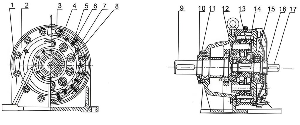
The cycloidal drive, or cycloidal speed reducer, was chosen for its compactness, high reduction ratio, and robustness—attributes ideal for embedding within the confined space of a screw shaft. The reducer primarily consists of an input shaft, an eccentric cam, cycloidal discs (or a single disc), and a ring of stationary pin gears (pinwheels). The reduction ratio $i$ for a single-stage cycloidal drive is given by:
$$ i = \frac{Z_p}{Z_p – Z_c} $$
where $Z_p$ is the number of pins on the stationary ring and $Z_c$ is the number of lobes on the cycloidal disc. For our model, with $Z_p = 8$ and $Z_c = 7$, the theoretical reduction ratio is $i = 8/(8-7) = 8:1$. The output speed is therefore $1/8$ of the input speed. In our practical assembly and simulation, a ratio of 1:7 was effectively realized to achieve a pronounced speed differential without inducing excessive torque or stalling.
The three-dimensional model was constructed in SOLIDWORKS. The screw was segmented into three distinct functional zones: a front regular conveying section, a middle variable-speed section housing the cycloidal drive and reverse-flighted elements, and a rear regular conveying section. The internal cavity of the middle section was precisely machined to accommodate the reducer assembly, ensuring a seamless transmission of torque from the high-speed input segment to the low-speed output segment of the screw.
3. Numerical Simulation Methodology
The flow field analysis was conducted using ANSYS CFX, a high-fidelity Computational Fluid Dynamics (CFD) tool. The non-Newtonian, viscous flow of soybean meal paste was simulated under steady-state, isothermal conditions (80°C). The following assumptions and models were applied:
- Material Model: Soybean meal was treated as an incompressible, generalized Newtonian fluid with power-law viscosity.
$$ \tau = \mu \dot{\gamma}^n $$
where $\tau$ is the shear stress, $\mu$ is the consistency index (1930 Pa·sn), $\dot{\gamma}$ is the shear rate, and $n$ is the power-law index (taken as 1 for a simplified Bingham-plastic-like approximation in the primary analysis). Density was set at 700 kg/m³. - Boundary Conditions:
- Inlet: Mass flow inlet with a velocity of 0.05 m/s (ensuring fully filled, stable flow).
- Outlet: Pressure outlet at 1 MPa.
- Walls: No-slip condition on both screw and barrel surfaces.
- Screw Motion: The front and rear sections rotated at 120 rpm. The middle section, driven via the cycloidal drive, rotated at 120/7 ≈ 17.14 rpm.
- Governing Equations: The simulation solved the continuity and Navier-Stokes equations:
$$ \nabla \cdot \vec{V} = 0 $$
$$ \rho (\vec{V} \cdot \nabla) \vec{V} = -\nabla p + \nabla \cdot \bar{\tau} $$
where $\vec{V}$ is the velocity vector, $\rho$ is density, $p$ is pressure, and $\bar{\tau}$ is the stress tensor. - Mesh: The fluid domain (the volume between the screws and barrel) was meshed with over 570,000 high-quality tetrahedral elements to resolve complex flow features.
4. Results and Analysis of the Flow Field
4.1 Macroscopic Pressure Field
The pressure field provides direct insight into the conveying and pumping efficiency, as well as the presence of restrictive elements. The comparative analysis reveals a fundamental difference in pressure development.
| Configuration | Pressure Trend Along Axis | Key Observation & Implication |
|---|---|---|
| Conventional Twin-Screw | Steady, monotonic increase from inlet to outlet. | Indicates consistent, unidirectional conveying with no major flow obstructions or re-circulation zones. Mixing relies mainly on intermeshing shear. |
| Novel Cycloidal Drive Twin-Screw | Increase (Front Section) → Sharp Decrease (Middle Section) → Increase (Rear Section). | The pressure drop in the middle section is critical. It signifies a flow restriction caused by the combination of the reverse-flighted element and the reduced screw speed from the cycloidal drive. This creates a “material dam” effect, forcing backflow and re-circulation, which intensely promotes dispersive mixing. |
4.2 Velocity Field and Flow Patterns
4.2.1 Velocity Magnitude and Vector Analysis
The velocity magnitude contours and vectors vividly illustrate the kinematic manipulation achieved by the internal cycloidal drive. In the conventional screw, the velocity field is relatively uniform along the channel, with high-speed regions consistently near the barrel wall. In the novel design, the middle section exhibits a pronounced reduction in velocity magnitude. The velocity vectors in this zone become more chaotic, with clear components opposing the main flow direction, confirming the induced backflow.
Quantitative data extracted along the central axis of the flow channel further solidifies this observation. The axial velocity profile for the conventional screw remains high and fairly constant in the working sections. For the novel screw, a distinct velocity valley is present in the axial coordinate range corresponding to the variable-speed segment (approximately 0.15m to 0.24m from the inlet).
| Metric | Conventional Screw | Novel Screw with Cycloidal Drive | Percentage Change/Improvement |
|---|---|---|---|
| Avg. Axial Velocity in Mixing Zone | ~0.35 m/s | ~0.18 m/s | ≈ -48% |
| Theoretical Local Residence Time in Mixing Zone* | tconv | tnovel ≈ (0.35/0.18) * tconv | ≈ +94% increase locally |
| Overall Mean Residence Time (Experimental) | 20.02 s (@120 rpm) | 24.05 s (@120 rpm) | ≈ +20% increase globally |
*Based on inverse relationship between axial velocity and residence time for a fixed zone length.
4.2.2 Cross-Sectional Flow Streamlines
Analyzing flow streamlines on cross-sections perpendicular to the screw axis offers a clear view of mixing efficacy. In a cross-section from the regular conveying section, streamlines are smooth, forming two large, coherent vortices—typical of drag-induced flow with limited inter-material layer penetration.
In stark contrast, a cross-section taken from the middle variable-speed segment reveals a completely transformed flow pattern. The streamlines are highly chaotic, fragmented, and form multiple small, intense vortices. Crucially, the presence of streamlines circling in the opposite direction to the main vortex is visible. This is a hallmark of excellent distributive mixing, as fluid elements are repeatedly folded, stretched, and split apart, exponentially increasing the interfacial area between different components of the feed mix.
5. Experimental Validation
To validate the CFD predictions, particularly the increase in residence time, a physical experiment was conducted on a modified twin-screw extruder. Soybean meal was used as the feedstock. The global screw speed was varied, and the mean residence time was measured from feed introduction to product discharge.
| Screw Speed (rpm) | Mean Residence Time – Conventional (s) | Mean Residence Time – Novel (s) |
|---|---|---|
| 80 | 30.42 | 36.54 |
| 100 | 24.95 | 29.96 |
| 120 | 20.02 | 24.05 |
| 140 | 16.54 | 19.82 |
| 160 | 14.85 | 17.81 |
The experimental data conclusively shows that at any given screw speed, the novel design with the integrated cycloidal drive increases the mean residence time by approximately 20%. This directly correlates with the velocity reduction observed in the simulation and confirms the design’s effectiveness in prolonging material processing time, a key factor for achieving thermal uniformity and complete chemical/physical reactions in the feed.
6. Optimization Analysis: Positioning of the Cycloidal Drive
An important design consideration is the axial placement of the cycloidal drive unit. We investigated three configurations:
- Base Optimal Design: Cycloidal drive in the middle segment.
- Alternative 1: Cycloidal drive in the front segment.
- Alternative 2: Cycloidal drive in the rear segment.
CFD analysis of these alternatives was performed, comparing axial pressure and velocity profiles. The key findings are summarized below:
| Configuration | Pressure Build-up Efficiency | Mixing Zone Definition & Intensity | Overall Assessment |
|---|---|---|---|
| Middle (Base Design) | Moderate and stable. Pressure drop in the middle clearly defines the mixing zone. | Optimal. Creates a distinct, intense mixing zone in the middle of the processing length, allowing for pre-conditioning and post-mixing stabilization. | Best Overall. Provides a balanced and well-defined processing sequence: Convey → Mix/Decelerate/Knead → Convey/Pressurize. |
| Front Segment | Weaker overall pressure development. | Early mixing is good, but material may de-pressurize and not be re-worked later in the process. | Suboptimal. May compromise final product texture and density due to inadequate final pressurization. |
| Rear Segment | Strong final pressure. | Mixing occurs too late. Material may not be homogenized before entering the final high-pressure zone, leading to inconsistent product. | Suboptimal. Risks incomplete mixing being “locked in” by the final pressurization stage. |
The analysis confirmed that positioning the cycloidal drive in the middle segment represents the optimal compromise. It effectively creates a dedicated, high-intensity mixing/reacting zone while maintaining sufficient length both before and after for stable feeding and final pressurization/forming, respectively.
7. Conclusion
This study successfully designed, simulated, and validated a novel twin-screw extruder configuration that significantly enhances mixing performance for feed applications. The core innovation lies in the internal integration of a cycloidal drive speed reducer to actively create a variable-speed processing zone, synergistically combined with a reverse-flighted screw element.
The key conclusions are:
- Dramatically Altered Flow Dynamics: The cycloidal drive reduces the local screw speed by a factor of 7, which directly decreases local axial velocity by approximately 50%. This increases the local material residence time by nearly 100%, allowing for more prolonged shear and thermal treatment.
- Induced Backflow and Intensive Mixing: The combination of reduced speed and reverse flighting in the middle segment causes a significant pressure drop and induces strong backflow and flow reorientation. Cross-sectional streamline analysis confirms the creation of chaotic, multi-vortical flow patterns characteristic of excellent distributive mixing.
- Experimental Confirmation: Physical experiments validated the core benefit, showing an approximate 20% increase in the overall mean residence time across a range of operating speeds, directly attributable to the kinematic manipulation by the cycloidal drive.
- Optimal Configuration: Systematic analysis of the reducer’s placement verified that positioning the cycloidal drive in the middle segment of the screw provides the most balanced and effective processing profile, ensuring both intensive mixing and adequate final product pressurization.
The cycloidal drive-enhanced twin-screw design presents a paradigm shift from global parameter adjustment to local kinematic control. This approach offers a powerful and mechanically elegant solution for intensifying mixing in extrusion processing, with direct applications in the feed, food, and polymer industries where blend homogeneity and structured texture are paramount. Future work will focus on optimizing the cycloidal drive geometry for specific torque requirements and exploring the scalability of this design to larger industrial extruders.