
In my years of experience as a mechanical engineer specializing in power transmission systems, I have extensively worked with cycloidal drives, particularly in applications like flour milling and other food processing industries. The cycloidal drive, known for its high reduction ratios and compact design, has become a cornerstone in modern machinery. This article delves into the intricacies of selecting, installing, using, and maintaining cycloidal drives, with a focus on practical insights and best practices. I will share detailed knowledge, supported by tables and formulas, to ensure optimal performance and longevity of these robust devices.
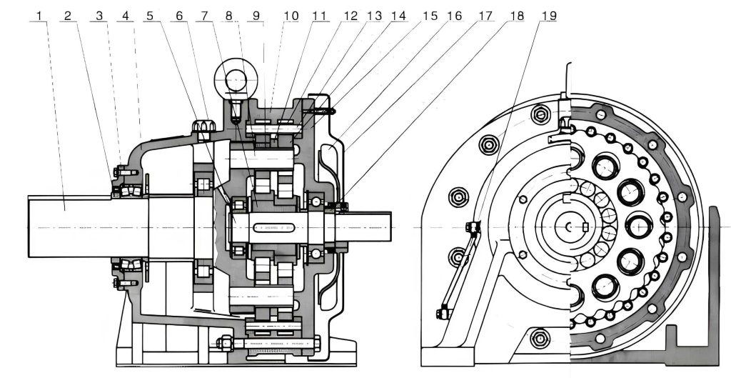
The cycloidal drive operates on a unique principle involving cycloidal motion and planetary gearing. Essentially, it consists of an input shaft with an eccentric bearing that drives a cycloidal disc, which meshes with stationary pin gears housed in the casing. This arrangement allows for high torque transmission with minimal backlash. The kinematic relationship can be described mathematically. Let the number of pins on the stationary ring gear be \( Z_p \) and the number of lobes on the cycloidal disc be \( Z_c \). The reduction ratio \( i \) for a single-stage cycloidal drive is given by:
$$ i = \frac{Z_p}{Z_p – Z_c} $$
For instance, if \( Z_p = 40 \) and \( Z_c = 39 \), the ratio \( i = 40 \), showcasing the high reduction capability. The efficiency \( \eta \) of a cycloidal drive typically ranges from 90% to 95%, calculated as:
$$ \eta = \frac{P_{\text{output}}}{P_{\text{input}}} \times 100\% $$
where \( P \) denotes power. This efficiency is superior to many other reducer types, making the cycloidal drive ideal for energy-sensitive applications. In food processing, such as flour mills, the cycloidal drive’s sealed design prevents contamination, aligning with hygiene standards. The following table summarizes key characteristics of cycloidal drives:
| Characteristic | Typical Value/Range | Importance |
|---|---|---|
| Reduction Ratio (Single Stage) | 6 to 119 | Enables high torque output from high-speed inputs |
| Efficiency | 90% – 95% | Reduces energy loss and operational costs |
| Noise Level | < 70 dB | Ensures quiet operation in industrial settings |
| Overload Capacity | Up to 200% of rated torque | Provides reliability under shock loads |
| Service Life | 20,000+ hours | Minimizes downtime and replacement frequency |
When selecting a cycloidal drive, I always emphasize choosing reputable brands with robust manufacturing capabilities. The precision required for components like cycloidal discs demands specialized machining equipment. A poor-quality cycloidal drive can lead to premature failure and safety hazards. For flour mills, factors like sanitary design, corrosion resistance, and sealed lubrication are critical. The cycloidal drive must be rated for continuous operation and capable of handling the specific loads of conveyors or elevators.
Installation is a pivotal phase where many errors occur. As I have observed, improper installation can drastically shorten the life of a cycloidal drive. The process must be meticulous. First, ensure the foundation is clean, level, and capable of supporting the reducer’s weight and operational forces. The alignment between the cycloidal drive and the driven equipment is crucial; misalignment induces parasitic forces that damage bearings and gears. Use dial indicators to measure radial and axial runout. The allowable misalignment varies by coupling type, but generally, for flexible couplings, it should not exceed 0.1 mm. Here’s a step-by-step guide I follow:
| Step | Procedure | Key Considerations |
|---|---|---|
| 1. Preparation | Inspect the cycloidal drive for damage. Check mounting surfaces and shafts. | Ensure no transportation damage; verify model matches application requirements. |
| 2. Mounting | Place the cycloidal drive on the base. Use shims or pads for leveling. | Shims should be high-grade steel or iron; limit to three layers max to avoid soft-footing. |
| 3. Alignment | Align input/output shafts with connected machinery using laser or dial gauges. | Aim for angular and parallel misalignment within coupling manufacturer’s specs. |
| 4. Securing | Tighten foundation bolts in a crisscross pattern to specified torque. | Over-tightening can distort the housing; use a torque wrench. |
| 5. Attachment | Connect output shaft to load (e.g., pulley, sprocket) via adapter or coupling. | Never hammer directly onto shaft; use threaded holes for extraction/insertion. |
| 6. Final Check | Verify all bolts are tight, alignment holds, and shaft rotates freely by hand. | Rotation should be smooth without binding or unusual resistance. |
For inclined installations, the cycloidal drive can be mounted at angles up to 15°. Beyond that, special lubrication systems or seals are necessary to prevent oil leakage and ensure all gears are wetted. The force analysis on the output shaft is vital. The cycloidal drive’s output shaft is designed primarily for torque transmission, not for high external axial or radial loads. If such loads exist, support bearings or additional structures must be used. The maximum allowable axial load \( F_a \) and radial load \( F_r \) can be estimated from manufacturer data, but as a rule of thumb, they should not exceed 10% of the rated output torque capacity. The relationship is approximated by:
$$ F_r \leq \frac{T}{k \cdot r} $$
where \( T \) is output torque, \( r \) is shaft radius, and \( k \) is a safety factor (typically 2 to 3). Exceeding these limits can lead to bearing failure and misalignment within the cycloidal drive.
Operational use of the cycloidal drive requires adherence to environmental and electrical specifications. From my practice, I recommend operating the cycloidal drive within its rated parameters. The input power supply should be stable: voltage at 380V ±5%, frequency at 50Hz ±2%. Ambient temperature conditions depend on altitude. At sea level up to 1000m, the operating range is -10°C to +40°C; from 1000m to 2000m, it’s -10°C to +30°C. The temperature rise of the oil sump under full load should not exceed 40°C above ambient. Monitoring this is essential; excessive heat indicates problems like overloading or inadequate lubrication. The input speed for standard cycloidal drives is around 1500 rpm, but for powers above 1.5 kW, I advise using 1000 rpm to reduce wear and enhance durability. The thermal dynamics can be modeled simplistically:
$$ \Delta T = \frac{P_{\text{loss}}}{C \cdot m} $$
where \( \Delta T \) is temperature rise, \( P_{\text{loss}} \) is power loss ( \( P_{\text{input}} \cdot (1 – \eta) \) ), \( C \) is specific heat of lubricant, and \( m \) is lubricant mass. Keeping \( \Delta T \) under 40°C ensures stable operation.
Lubrication is the lifeblood of any cycloidal drive. In food industry applications like flour mills, I insist on using specialized grease that is non-toxic, resistant to washout, and has high adhesion. The cycloidal drive is typically factory-filled with such grease, which minimizes leakage and contamination. The grease level should be maintained at the center of the sight glass. Overfilling can cause churning and overheating, while underfilling leads to insufficient lubrication and accelerated wear. The regreasing interval depends on operating hours and conditions. For continuous duty, I recommend replenishing grease every 500 hours and completely replacing it every 2000 hours or annually, whichever comes first. The grease quantity \( Q \) for replenishment can be calculated based on the cycloidal drive’s size:
$$ Q = V \cdot \rho \cdot f $$
where \( V \) is internal free volume (from manual), \( \rho \) is grease density (~0.9 g/cm³), and \( f \) is a factor (0.1 to 0.2 for top-up). Below is a lubrication schedule table I use:
| Operation Phase | Action | Frequency/Duration |
|---|---|---|
| Initial Run | First grease change after 200 hours | Removes break-in debris and particles |
| Normal Operation | Inspect grease level weekly; top-up if low | Ensure level at sight glass midpoint |
| Scheduled Maintenance | Complete grease replacement | Every 2000 hours or 6 months of continuous use |
| Harsh Conditions | Shorten intervals by 30% | High dust, moisture, or temperature fluctuations |
Maintenance and保养 are proactive measures that I cannot overstate. A well-maintained cycloidal drive can last decades. Regular inspections should focus on several areas. First, check all fasteners for tightness—foundation bolts, coupling screws, and mounting pads. Loose bolts induce vibration that can crack housings. Second, monitor for unusual noises or vibrations using simple tools like stethoscopes or vibration pens. Abnormal sounds often indicate internal wear or misalignment. Third, inspect seals for leaks. The shaft seals are critical in keeping contaminants out and grease in. If grease appears dirty or contains metal flakes, immediate disassembly and cleaning are warranted. The wear rate of components like the cycloidal disc and pins can be assessed periodically. The theoretical wear volume \( W \) after time \( t \) is given by Archard’s wear equation:
$$ W = k \cdot F_n \cdot s $$
where \( k \) is wear coefficient, \( F_n \) is normal load, and \( s \) is sliding distance. For cycloidal drives, \( s \) relates to the number of cycles, emphasizing the need for proper lubrication to reduce \( k \).
When disassembling a cycloidal drive for repair, I follow a strict protocol. After draining grease, carefully separate the housing halves. The cycloidal discs and pins should be inspected for pitting, scoring, or excessive wear. The eccentric bearing must be checked for play. Reassembly requires precision: cycloidal discs must be phased correctly relative to each other to ensure smooth motion. The phase relationship is determined by the tooth counts and is often marked by manufacturers. If replacing bearings, use thermal expansion methods for installation—avoid hammering. The housing faces should be cleaned meticulously and sealed with a fresh gasket or silicone sealant. Gasket thickness should be 0.5 mm to 1 mm to prevent compression issues. After reassembly, hand-rotate the input shaft至少 3 full revolutions to ensure no binding before powering on.
Common failures in cycloidal drives include overheating, noise increase, and output shaft wobble. Troubleshooting these requires systematic analysis. Below is a table I’ve compiled based on field experiences:
| Symptom | Possible Cause | Remedial Action |
|---|---|---|
| Overheating (>80°C sump temp) | Overloading, incorrect lubrication, blocked vents | Reduce load, check grease type/level, clean housing exterior |
| Excessive Vibration | Misalignment, worn bearings, loose mounts | Realign shafts, replace bearings, tighten all bolts |
| Oil/Grease Leakage | Damaged seals, overfilled, sealant failure | Replace seals, adjust level, reapply sealant on housing |
| Unusual Grinding Noise | Contaminated grease, broken teeth on cycloidal disc | Flush and regrease, inspect and replace damaged components |
| Reduced Output Torque | Internal wear, slipping coupling | Check cycloidal disc and pin wear, tighten coupling |
In面粉加工, the cycloidal drive often runs continuously for months. I advocate for installing condition monitoring sensors—temperature and vibration—to predict failures. Data loggers can track trends, allowing maintenance before catastrophic breakdown. The return on investment is high given the cost of downtime in food production.
Another aspect is the selection of cycloidal drive size. Using the service factor method, the required rated torque \( T_r \) is:
$$ T_r = T_a \cdot S_f $$
where \( T_a \) is application torque and \( S_f \) is service factor (from 1.2 for uniform loads to 2.0 for heavy shock loads). For conveyors in flour mills, \( S_f \) typically is 1.5. Always consult manufacturer catalogs for exact ratings. The cycloidal drive’s inertia matching should also be considered for dynamic applications. The reflected inertia \( J_{\text{ref}} \) on the cycloidal drive input is:
$$ J_{\text{ref}} = \frac{J_{\text{load}}}{i^2} $$
where \( J_{\text{load}} \) is load inertia. Keeping \( J_{\text{ref}} \) within the motor’s capability ensures smooth acceleration.
In conclusion, the cycloidal drive is a marvel of engineering that, when properly selected, installed, and maintained, offers unparalleled reliability. My firsthand experience confirms that attention to detail in alignment, lubrication, and periodic checks extends service life significantly. The cycloidal drive’s efficiency and compactness make it ideal for modern industrial applications, especially where hygiene and space are constraints. By following the guidelines outlined—supported by tables and formulas—operators can maximize performance and minimize costs. Remember, the cycloidal drive is not just a component; it’s a system that demands respect and care. Through proactive maintenance and informed operation, the cycloidal drive will serve as a dependable workhorse for years to come.
Finally, I encourage continuous learning. New materials and sealing technologies are evolving, enhancing cycloidal drive capabilities. Staying updated with manufacturer recommendations ensures that your cycloidal drive operates at peak efficiency. Whether in flour milling or other sectors, the principles remain: precision installation, correct lubrication, and vigilant maintenance are the keys to success with cycloidal drives.