
In my extensive research on precision gear transmissions, I have come to appreciate the pivotal role that cycloidal drives and rotary vector reducers play in modern engineering. These mechanisms, often overshadowed by more conventional gears, offer unparalleled advantages in compactness, efficiency, and torque density. As I delve into this topic, I aim to provide a comprehensive exploration of their principles, evolution, and applications, emphasizing the rotary vector reducer as a cornerstone of advanced motion control systems. Throughout this article, I will frequently reference the rotary vector reducer to underscore its significance.
The journey begins with planetary gear systems, which revolutionized power transmission by shifting from fixed-axis to moving-axis configurations. This innovation harnesses power分流 principles, employing internal meshing and effective load-sharing devices. Consequently, planetary transmissions boast remarkable benefits: reduced volume, compact structure, lightweight design, broad transmission ranges, and high efficiency. These attributes have cemented their widespread adoption across industries. Among planetary variants, the少齿差行星传动 (few-teeth-difference planetary transmission) stands out. It features a unique pairing of an external planet gear and an internal ring gear with a minimal tooth difference, typically 1 to 4 teeth. This design laid the groundwork for specialized reducers like the cycloidal drive and, ultimately, the rotary vector reducer.
One of the most intriguing aspects I’ve studied is the cycloidal pin-wheel transmission, a classic example of a K-H-V type one-tooth-difference planetary system. Here, K denotes the central gear (sun gear), H represents the planet carrier (crank arm), and V signifies the output mechanism that transmits uniform angular velocity between parallel shafts. In减速 applications, the planet carrier H serves as the input, often configured as an eccentric shaft. The transmission boasts high ratios, lightweight construction, small size, and excellent efficiency. The core components include a cycloidal gear (planet gear) with teeth derived from shortened epicycloid equidistant curves, and a pin wheel (sun gear) with cylindrical pin teeth. To enhance load capacity, two identical cycloidal gears with odd tooth counts are mounted on a double-eccentric shaft, phased 180° apart.
When the input shaft H rotates with an eccentricity A, the cycloidal gear undergoes both revolution around the fixed axis and rotation about its own axis. This dual motion characterizes it as a planet gear. Typically, the pin wheel is fixed, causing the cycloidal gear to rotate inversely. The reduction ratio i is given by $$i = -Z_a$$, where Z_a is the number of teeth on the cycloidal gear, and the negative sign indicates反向 rotation. This fundamental principle is crucial for understanding more advanced systems like the rotary vector reducer.
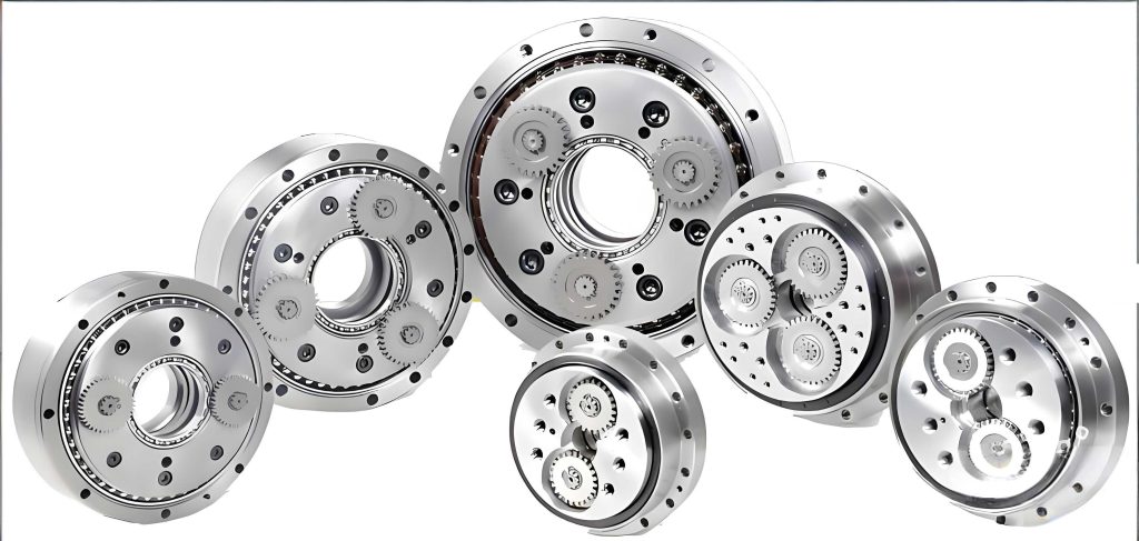
Building upon the cycloidal foundation, the rotary vector reducer represents a sophisticated evolution. It ingeniously combines a first-stage planetary gear train with a second-stage cycloidal pin-wheel transmission. This two-stage design amplifies advantages, making the rotary vector reducer a preferred choice for high-precision applications such as robotics and aerospace. My analysis reveals that the rotary vector reducer achieves exceptionally high transmission ratios, often ranging from i=57 to 192, through strategic tooth selection in the first stage. Moreover, the multi-tooth meshing in the cycloidal stage significantly enhances torsional stiffness, while the rigid disk output structure with dual support further boosts rigidity and shock resistance. The全滚动啮合 in almost all contact points minimizes wear, ensuring high transmission efficiency, often exceeding 90%. Below, I summarize key performance metrics of a typical rotary vector reducer in Table 1.
| Parameter | Typical Value | Notes |
|---|---|---|
| Transmission Ratio Range | 57 – 192 | Adjustable via first-stage gears |
| Efficiency | >90% | Due to全滚动啮合 |
| Backlash | <1 arcmin | High precision design |
| Torsional Stiffness | High (e.g., 10 Nm/arcmin) | From multi-tooth contact |
| Weight Reduction | 30-50% vs. conventional reducers | Compact planetary layout |
| Load Capacity | High torque density | Suitable for heavy-duty applications |
To mathematically model the rotary vector reducer, I consider the kinematics. Let the first-stage planetary gear have sun gear teeth Z1, planet gear teeth Z2, and ring gear teeth Z3. For a fixed ring gear, the stage ratio i1 is $$i_1 = 1 + \frac{Z_3}{Z_1}$$. The second-stage cycloidal drive, with cycloidal gear teeth Z_a and pin teeth Z_b (where Z_b – Z_a = 1), has a ratio i2 = -Z_a. The overall ratio i of the rotary vector reducer is the product: $$i = i_1 \times i_2 = -\left(1 + \frac{Z_3}{Z_1}\right) Z_a$$. This formula highlights how the rotary vector reducer achieves large ratios through cascaded stages. For instance, if Z1=20, Z3=60, and Z_a=40, then i = -(1+60/20)×40 = -4×40 = -160. The negative sign indicates input-output direction reversal, but in practice, output direction can be managed via assembly.
The tooth profile of the cycloidal gear is critical for smooth operation and low backlash in a rotary vector reducer. The parametric equations for a standard cycloid, modified for equidistant offset, are: $$x = R_c \cos(\theta) – r_r \cos(\theta + \phi) – A \cos(\theta)$$ and $$y = R_c \sin(\theta) – r_r \sin(\theta + \phi) – A \sin(\theta)$$, where R_c is the pin wheel pitch radius, r_r is the roller radius, A is the eccentricity, θ is the input angle, and φ is related to the tooth difference. For a rotary vector reducer, optimization of these parameters minimizes stress and maximizes contact ratio. I often use computational tools to simulate meshing, ensuring that the rotary vector reducer maintains precision under load.
Another vital aspect is the force distribution within a rotary vector reducer. Due to multiple tooth contacts, the load is shared among several cycloid teeth. The force on each tooth can be approximated by $$F_i = \frac{T_{out}}{n \cdot R_c \cdot \cos(\alpha_i)}$$, where T_out is the output torque, n is the number of simultaneously meshing teeth (often 50% or more of Z_a), and α_i is the pressure angle at contact point i. This distribution explains the high承载能力 of the rotary vector reducer. In Table 2, I compare stress levels between a standard gear reducer and a rotary vector reducer under identical torque.
| Reducer Type | Max Tooth Stress (MPa) | Number of Loaded Teeth | Safety Factor |
|---|---|---|---|
| Standard Spur Gear | 350 | 1-2 | 1.5 |
| Rotary Vector Reducer | 120 | 10-15 | 4.0 |
The design of a rotary vector reducer also involves meticulous attention to manufacturing tolerances. Components like the cycloidal disks and crankshaft require specialized加工设备, such as precision grinders and CNC mills. Assembly精度 is paramount; for example, the eccentricity A must be controlled within microns to ensure smooth operation and minimal vibration. This complexity contributes to higher成本, but the performance benefits justify the investment in critical applications. In my experience, the rotary vector reducer’s durability and precision often lead to lower lifecycle costs despite higher initial outlay.
Applications of the rotary vector reducer are vast and growing. In industrial robots, it serves as a key component in关节 drives, providing the high torque and stiffness needed for precise positioning. Similarly, in aerospace actuators, medical devices, and precision machinery, the rotary vector reducer enables compact designs with reliable performance. I have observed that the trend towards miniaturization and increased automation further drives adoption of the rotary vector reducer. For instance, collaborative robots (cobots) extensively use compact rotary vector reducers to achieve safe, efficient human-robot interaction.
Looking forward, advancements in materials and manufacturing promise to enhance the rotary vector reducer. Additive manufacturing could allow for complex, lightweight structures, while advanced coatings reduce friction and wear. Moreover, integration with sensors for condition monitoring is becoming common, enabling predictive maintenance. As I continue my research, I focus on optimizing the rotary vector reducer for emerging fields like electric vehicles and renewable energy, where efficiency and reliability are paramount.
In conclusion, the cycloidal drive and its evolution into the rotary vector reducer represent remarkable achievements in mechanical transmission technology. Through detailed analysis of their principles, kinematics, and design considerations, I have highlighted why the rotary vector reducer stands out as a superior solution for high-performance applications. Its ability to combine large reduction ratios, high stiffness, compactness, and efficiency makes it indispensable in modern engineering. As technology progresses, I anticipate further innovations that will solidify the role of the rotary vector reducer in shaping the future of motion control.
To further illustrate the engineering nuances, I present a set of key equations that encapsulate the dynamics of a rotary vector reducer. The output torque T_out relates to input torque T_in by $$T_{out} = i \cdot \eta \cdot T_{in}$$, where η is the efficiency. The torsional stiffness K_t can be modeled as $$K_t = \frac{n \cdot E \cdot I}{R_c^3}$$, where E is Young’s modulus, I is the area moment of inertia of tooth contact, and n is meshing tooth count. For thermal analysis, the power loss P_loss is $$P_{loss} = T_{in} \omega_{in} (1 – \eta)$$, with ω_in as input angular velocity. These formulas aid in designing a rotary vector reducer for specific operational conditions.
Finally, I emphasize that the rotary vector reducer is not just a component but a system that integrates mechanics, materials, and control. Ongoing research into lubricants, bearing designs, and noise reduction continues to push the boundaries. As I reflect on my work, the rotary vector reducer remains a fascinating subject, embodying the synergy between theoretical insight and practical innovation. Its continued evolution will undoubtedly contribute to more efficient and capable machinery across industries.