
The advancement of industrial automation, driven by initiatives such as “Industry 4.0” and “Made in China 2025,” has led to the widespread adoption of robotic systems for repetitive tasks like welding, painting, and material handling. Among these, robotic loading and unloading, or pick-and-place operations, are fundamental to streamlining production lines in automotive, stamping, and various manufacturing sectors. While the operation itself may seem straightforward, its high repetition and physical demand make the efficiency of the material handling robot a critical factor for overall productivity. The success of such operations heavily relies on the end effector – the specialized tool interfacing directly with the workpiece. Given the vast diversity in workpiece geometries, a universal gripper remains elusive. Therefore, a practical strategy involves deploying specialized end effectors tailored to specific shapes, which can be quickly interchanged on a robotic arm. This work focuses on the design, analysis, and experimental validation of a dedicated end effector for the manipulation of workpieces characterized as spherical sectors. A spherical sector is defined as the portion of a sphere cut off by a plane, presenting a unique geometric challenge for reliable grasping.
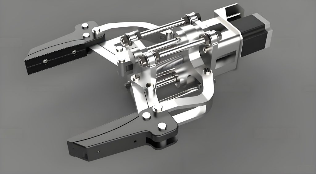
The primary mechanism for this end effector is vacuum adhesion. The overall mechanical architecture comprises several integrated modules: a quick-change adapter for connection to an industrial robot arm, a standard linear actuator (pneumatic cylinder) providing the primary extension/retraction motion, a sensor module with force feedback sensors, a fail-safe fixation module, and the core vacuum吸附 module. The吸附 module utilizes specially designed vacuum cups. Compared to standard flat suction cups, bellows-type cups with folds are preferred as they offer greater compliance and deformation range, enabling better sealing on curved surfaces. The operational sequence of the end effector is a critical aspect of its design logic. The cycle begins with the robot positioning the end effector above the target. The cylinder extends, bringing the suction cups into contact with the spherical sector body. Once a vacuum is established and adsorption confirmed, the cylinder retracts, lifting the workpiece. Subsequently, the fail-safe mechanical claws of the fixation module engage, physically cradling the workpiece to prevent any accidental drop during high-speed robot motion. For placement, the process is reversed: the claws disengage, the cylinder extends to position the workpiece, the vacuum is released, and the cylinder retracts, completing the cycle. This sequenced operation ensures both secure grasping and safe transit.
The foundational challenge in designing this end effector lies in the viability of vacuum adhesion on a spherical surface. Unlike吸附 flat, horizontally placed objects where the吸附 force is primarily normal to the surface,吸附 a spherical sector introduces angular constraints. The吸附 force must counteract gravity through a combination of direct suction normal to the local surface and friction. We analyze two key states: the initial吸附 state when cups first contact the workpiece, and the working吸附 state when the workpiece is lifted. In the working state, assuming symmetric arrangement of cups, horizontal force components cancel out. The vertical force equilibrium for a single cup is governed by its orientation angle $\alpha$, defined as the angle between the cup’s central axis and the horizontal plane.
The gravitational force on the workpiece must be balanced by the vertical components from all cups:
$$ G \le \frac{n \times (F_y^{吸} + F_y^{f})}{a} = \frac{n \times (F_{吸} \cdot \sin \alpha + F_f \cdot \cos \alpha)}{a} $$
where $G$ is the workpiece weight, $n$ is the number of cups, $F_{吸}$ is the vacuum吸附 force per cup, $F_f$ is the frictional force, and $a$ is a safety factor. The frictional force is $F_f = F_{吸} \cdot \mu$, where $\mu$ is the coefficient of friction. The vacuum吸附 force for a cup is given by:
$$ F_{吸} = S \times \frac{P}{101.3} \times 10.13 \approx S \times \frac{P}{10} $$
where $S$ is the effective area of the cup (in mm²) and $P$ is the vacuum level (in kPa).
Furthermore, the cups must be arranged on the spherical surface without interference. For $n$ idealized cups of diameter $d$ on a sphere of radius $R$, the non-interference condition is:
$$ n \cdot d \le \pi \cdot 2 \cdot R \cdot \cos(\alpha) $$
Combining the force equilibrium (ignoring friction for a conservative estimate on $\alpha$) and the geometric constraint, the feasible range for the cup angle $\alpha$ is:
$$ \arcsin\left(\frac{a \cdot G}{n \cdot F_{吸}}\right) \le \alpha \le \arccos\left(\frac{n \cdot d}{2\pi \cdot R}\right) $$
The maximum holding force $F_{\text{吸}}^{\text{max}}$ of the end effector, combining suction and friction, is:
$$ F_{\text{吸}}^{\text{max}} = n \times (F_{吸} \cdot \sin \alpha + F_{f} \cdot \cos \alpha) = n \times F_{吸} (\sin \alpha + \mu \cos \alpha) $$
To understand the relationship between parameters, we analyze the maximum吸附 force for $n=4$, $P=-70 \text{ kPa}$, $R=150 \text{ mm}$, and varying $\mu$ and cup diameter $d$. The results are summarized in the table below, where $F_{\text{吸}}$ is calculated for each $d$.
| μ | d (mm) | α for Max $F_{\text{吸}}^{\text{max}}$ (°) | Max $F_{\text{吸}}^{\text{max}}$ (N) | Note |
|---|---|---|---|---|
| 0.2 | 40 | 78 | 359.9 | Theoretical max (α limited by geometry to ~80°) |
| 0.2 | 80 | 78 | 1440.0 | Theoretical max (α limited by geometry to ~70°) |
| 0.4 | 40 | 68 | 380.1 | |
| 0.4 | 80 | 68 | 1520.4 | |
| 0.6 | 40 | 59 | 411.6 | |
| 0.6 | 80 | 59 | 1646.5 | |
| 0.8 | 40 | 51 | 452.0 | |
| 0.8 | 80 | 51 | 1808.2 |
The analysis reveals that for lower friction coefficients, the optimal angle $\alpha$ for maximum force is higher, approaching the geometric limit. For higher friction, the optimal angle shifts lower. In practice, an angle $\alpha$ around 55-70° is often a suitable compromise considering both force and spatial constraints. This modeling is crucial for the initial sizing and configuration of the vacuum吸附 module within the end effector.
Another vital aspect of the vacuum system is its robustness against leaks. The gas load $Q$ in the vacuum chamber (the volume enclosed by the cups and workpiece) is primarily the sum of the inherent leak rate $Q_1$ and the initial atmospheric gas $Q_5$. For this end effector, outgassing and permeation are negligible. The simplified pumping equation is:
$$ V \frac{dp}{dt} = -S_e p + Q_1 $$
where $V$ is the volume of the vacuum system, $S_e$ is the effective pumping speed, $p$ is the pressure, and $t$ is time. The leak rate $Q_1$, dependent on surface roughness and sealing quality, is best determined empirically. Understanding this relationship allows for estimating the safety window in case of pump failure.
Reliability is paramount for any industrial end effector. We employ Fault Tree Analysis (FTA) to systematically evaluate potential failure modes. The top event (A) is “End Effector Failure.” We assume stable pneumatic supply and no electronic control faults. The fault tree is constructed based on the operational workflow, incorporating hardware failures (B2), accidental operational faults (B3), and sensor faults (B4). These are further broken down into basic events like cylinder damage (C2), cup damage (C3), excessive radial load on cylinder (C5), improper吸附 angle (C7), loss of seal during movement (C8), and failures of the mechanical claw components or their sensors (C9-C16). Logic gates (AND, OR) model the interaction between these events.
Qualitative analysis using the upward method yields 14 minimal cut sets, highlighting the most vulnerable failure combinations:
$$ K_1:\{C_1\}, K_2:\{C_2\}, …, K_9:\{C_9, C_{10}, C_{11}\}, K_{10}:\{C_9, C_{10}, C_{12}\}, K_{11}:\{C_9, C_{11}, C_{12}\}, K_{12}:\{C_{13}, C_{14}\}, K_{13}:\{C_{15}\}, K_{14}:\{C_{16}\} $$
This shows that single-point failures exist (e.g., assembly fault C1, or any major component failure), but also that the fail-safe claw requires concurrent failures of multiple sub-components to fail dangerously (K9-K11).
For quantitative analysis, we assign failure probabilities based on component maturity. Standard purchased components (cylinders, cups, sensors) are assigned a low failure rate of $10^{-5}$. Custom-made mechanical assemblies like the claw are assigned a rate of $10^{-4}$. Operational errors (misalignment, overload) are assigned a higher probability of $10^{-3}$. The probability of an OR gate output $P(X)$ and an AND gate output $P(Y)$ are:
$$ P(X) = 1 – \prod_{i=1}^{n} [1 – P(x_i)] $$
$$ P(Y) = \prod_{i=1}^{n} P(y_i) $$
Calculating upward through the tree, the probability of the top event A (end effector failure per operation cycle) is approximately $P(A) \approx 0.004143$, or 0.4143%. We also calculate the probability importance and criticality importance of each basic event to prioritize improvement efforts.
| Basic Event | Failure Probability | Probability Importance | Criticality Importance |
|---|---|---|---|
| C1 (Assembly Fault) | 0.0001 | 1 | 0.0241 |
| C2, C3, C4 (Component Fail) | 0.00001 | 1 | 0.0024 |
| C5, C6, C7, C8 (Operational Error) | 0.001 | 1 | 0.2415 |
| C9 (Claw Assembly Fault) | 0.0001 | ~3e-8 | ~7.2e-10 |
| C15, C16 (Sensor Fail) | 0.00001 | 1 | 0.0024 |
The analysis clearly indicates that operational errors (C5-C8) have the highest criticality importance, suggesting that ensuring proper robot positioning and avoiding overloads is the most effective way to improve the reliability of this end effector.
To validate the design and analysis, a physical prototype of the end effector was built and tested on a stationary platform (simulating a robot arm). The target workpiece was a spherical sector (hemisphere) of diameter 300 mm, mass 20 kg, made of aluminum with a machined surface finish. A cup angle $\alpha$ of 55° was selected for the prototype.
The first test involved continuous pick-place cycles to simulate standard operation. Over five sets of 100 consecutive cycles (500 total), only one failure occurred, attributed to excessive radial force on the cylinder during misalignment. This observed failure rate of 0.2% is consistent with the FTA-predicted rate of ~0.41%, validating the reliability model.
The second test characterized the positional tolerance of the end effector. By offsetting the workpiece relative to the end effector’s center, the viable pickup envelope was mapped. The end effector could successfully pick up and secure the workpiece with all three safety claws engaged if the lateral offset was within ±4 mm. For offsets between ±4 mm and ±8 mm, pickup was sometimes possible, but only two claws would engage in the secured state. Offsets beyond ±8 mm consistently resulted in pickup failure. This defines the required positioning accuracy for the robotic arm using this end effector.
The third test measured the system leak rate $Q_1$ using the static pressure rise method. After achieving an initial vacuum of -86.7 kPa and isolating the system, the pressure rise was recorded until the workpiece dropped. For a system volume $V \approx 51$ L, the pressure change $\Delta p = 71.2$ kPa over $\Delta t = 883$ s. The average leak rate was calculated as:
$$ Q_{1t} = V \cdot \frac{\Delta p}{\Delta t} = 51 \times \frac{71.2}{883} \approx 4.09 \text{ Pa·L/s} $$
This empirical value is essential for calculating the safety margin or hold time in case of vacuum pump failure.
The final test simulated a power failure during operation. With the workpiece securely吸附 and the safety claws engaged, cutting power to the vacuum pump and valves was simulated. Due to the system’s internal volume (including a 50L vacuum reservoir) and the characterized leak rate, the workpiece remained吸附 for a significant period—over 865 seconds starting from -85 kPa. This demonstrates that the end effector design provides a substantial inherent safety buffer against sudden power loss, even before considering the mechanical lock from the safety claws.
In conclusion, the design of a vacuum-based end effector for spherical sector manipulation presents unique geometric and force-balance challenges. Through detailed mechanical design, theoretical modeling of the吸附 mechanics, and comprehensive reliability analysis via FTA, a robust solution was developed. The experimental prototype confirmed the functional and reliability predictions. The end effector demonstrated a high success rate in continuous operation, a defined operational envelope, a quantifiable leak rate, and inherent safety during power failures. This systematic approach—from modeling and simulation to physical testing—ensures that the specialized end effector is not only effective but also reliable and safe for integration into an automated industrial handling system. Future work could involve optimizing the cup material and profile for lower leak rates on rougher surfaces or integrating adaptive control based on the real-time sensor feedback from the end effector.