
The development of practical, hands-on experimental platforms is crucial for cultivating strong engineering skills in fields like automation and robotics. While Programmable Logic Controllers (PLCs) are a cornerstone of industrial control systems, educational setups often face limitations, ranging from simplistic simulation software to expensive, pre-packaged, and opaque training stations. These setups can isolate students from the complete system development lifecycle, focusing only on programming fragments without engaging with mechanical design, sensor integration, or full hardware-software co-design. To bridge this gap, a project was initiated to create an integrated, open-ended educational platform. This platform centers on the development of a sophisticated motion control system for a multi-legged robot dog, utilizing a Siemens S7-200 PLC for core logic and a touchscreen Human-Machine Interface (HMI) for supervisory control and interaction. This article details the mechanical analysis, control system architecture, software design, and integration lessons learned from this first-person development journey, aiming to provide a comprehensive template for practical mechatronics education.
Mechanical Architecture and Kinematic Analysis of the Robot Dog
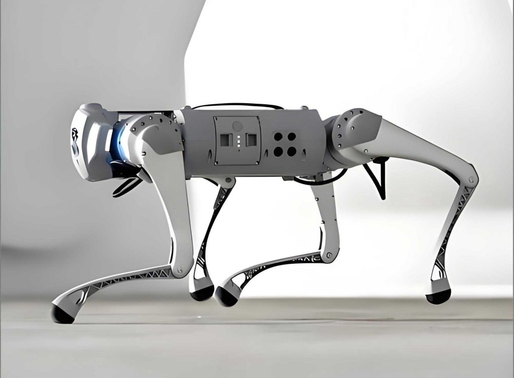
The electromechanical design of the robot dog serves as the foundational physical plant for the control system. The prototype was constructed primarily from aluminum alloys, offering a robust yet lightweight structure suitable for repeated experimental use. Its anatomy is decomposed into four primary actuated subsystems: the head, the torso (or body), the rear leg, and the tail. Each subsystem is driven by an independent 24V DC geared motor, translating rotary motion into specific linear or oscillatory movements through precise mechanical transmissions.
The head assembly employs a leadscrew mechanism. The rotation of the motor is converted into linear translation of a nut, which is linked to the head, enabling pitch motion (nodding up and down). The torso incorporates a rack-and-pinion or a slider-crank system, where a motor-driven gear engages with a linear rail, allowing the main body to extend and retract, mimicking a stretching or compressing gait. The rear leg utilizes another leadscrew to raise and lower the limb, providing the essential stepping action. The tail mechanism is the simplest, involving a direct drive from the motor to produce a reciprocating swinging motion. A simplified kinematic model for a single leg’s vertical motion can be represented. If the leadscrew has a pitch $p$ (distance per revolution) and the motor rotates at an angular velocity $\omega_m(t)$, the linear vertical displacement $y(t)$ of the foot relative to the body is given by:
$$ y(t) = \frac{p}{2\pi} \int_0^t \omega_m(\tau) d\tau = \frac{p}{2\pi} \theta_m(t) $$
where $\theta_m(t)$ is the motor’s angular position. This fundamental relationship forms the basis for open-loop position control via timed motor actuation in the initial design.
The movement of a walking robot dog is a complex, coordinated sequence of these individual motions. A stable, primitive gait was achieved by synchronizing the three main motors (head, torso, leg) in a specific temporal sequence, while the tail motor operated independently for ambient expression. This sequence, derived from empirical timing tests to prevent mechanical overtravel, defines the core “walking algorithm” for the PLC.
Control System Hardware Design and Integration
The hardware architecture was designed for clarity, safety, and pedagogical value. At its heart is a modular Siemens S7-200 PLC, chosen for its reliability and widespread industrial use. The configuration includes a CPU 224XP module (for processing and basic I/O), a power supply module (PS207), and a digital I/O expansion module (EM223). This modular approach allows students to understand system composition and address I/O requirements.
The interface between the low-voltage logic of the PLC (24V DC) and the motor power circuits is critical. Each of the four DC motors is controlled via an H-bridge circuit constructed using DS2Y-S-DC12V relays. This classic design allows bi-directional current flow through the motor, enabling forward and reverse motion. A typical circuit for one motor involves two relays. Energizing the coil of Relay 1 connects the motor to the power supply with a specific polarity, causing forward motion. Energizing Relay 2 reverses the polarity for reverse motion. Crucially, the PLC program and the circuit design must incorporate hardware and software interlocking to prevent the simultaneous energization of both relays, which would cause a short circuit. A series resistor is placed in line with each relay coil to ensure the PLC’s digital output, typically sourcing 24V, correctly operates the 12V relay coil without damage.
The system offers dual input modalities: traditional tactile pushbuttons and a modern touchscreen HMI (Siemens SMART 700). The HMI communicates with the PLC via an MPI/PROFIBUS connection, while a separate PC/PPI cable is used for programming both the PLC and the HMI from a development computer. The complete I/O mapping was carefully planned to allocate resources between direct button controls and HMI-initiated commands via internal PLC markers (M memory). This dual-channel input strategy is a key educational feature, demonstrating different industrial control interfaces. The I/O allocation is summarized in Table 1.
| Input Address | Function (Physical Device) | Output Address | Function (Actuator Control) |
|---|---|---|---|
| I0.0 – I0.7 | Jog Controls for 4 Motors (Buttons) | Q3.0, Q3.1 | Head Motor Forward / Reverse |
| I1.2 | System Auto-Run Start (Button) | Q3.2, Q3.3 | Torso Motor Forward / Reverse |
| I1.3 (NC) | System Emergency Stop (Button) | Q3.4, Q3.5 | Rear Leg Motor Forward / Reverse |
| I1.4 | Tail Auto-Swing Start (Button) | Q3.6, Q3.7 | Tail Motor Forward / Reverse |
| I1.5 (NC) | Tail Swing Stop (Button) | ||
| M2.0 (from HMI) | System Auto-Run Start (HMI Button) | ||
| M2.1 (from HMI) | System Stop (HMI Button) |
Note: NC denotes a Normally Closed contact in the physical wiring. HMI inputs map to internal memory bits (M) to avoid conflict with physical I/O addresses.
Software Design: PLC Logic and HMI Configuration
The control logic for the robot dog was implemented in ladder logic (LAD) on the S7-200 PLC. The program is structurally divided into several key routines: a main walking sequence, independent jogging controls, and the tail oscillation subroutine.
Core Walking Sequence Algorithm
The walking gait is an open-loop time-based sequence. From empirical measurements, the maximum travel times for the head ($T_h$), torso ($T_t$), and leg ($T_l$) actuators were determined. To ensure safe operation without limit switches, the commanded movement times were set slightly below these maximums (e.g., 36s instead of 40s). The sequence for one complete step cycle was encoded using timer chains (TON instructions) and internal flags. The fundamental periodic sequence for the three main axes can be described as a state machine with four primary phases, as outlined in Table 2.
| Cycle Phase | Duration (Approx.) | Head Motor | Torso Motor | Rear Leg Motor | Tail Motor |
|---|---|---|---|---|---|
| Phase 1 | 36 s | Forward (Up) | Reverse (Retract) | Forward (Down) | Oscillating (0.5s period) |
| Phase 2 | 36 s | Reverse (Down) | Forward (Extend) | Idle | |
| Phase 3 | 15 s | Forward (Up) | Reverse (Retract) | Reverse (Up) | |
| Phase 4 | 15 s | Reverse (Down) | Forward (Extend) | Idle |
This sequence creates a coordinated motion where the body rocks forward and back while the leg lifts, steps forward, and lowers. The main program flow is governed by a master auto-run flag (triggered by I1.2 or M2.0). When activated, it initiates Timer T1 for Phase 1. The expiration of T1 triggers the de-energization of the Phase 1 outputs, a short interlock delay to ensure motor stop, and then the energization of the Phase 2 outputs along with Timer T2, and so on. This creates a continuous loop until the stop signal (I1.3 or M2.1) breaks the cycle.
Implementation of the Tail Oscillation Subroutine
The tail wagging function is a clear example of a timed oscillator implemented in ladder logic. As per the ladder diagram excerpt described in the source material, the logic uses two timers in a closed loop to generate a square wave output. Let $T_{on}$ be the swing duration in one direction (0.5s) and $T_{dead}$ be a short dead time (20ms) to allow the motor to stop completely before reversing. The logic can be abstracted as a state machine with two states, $S_F$ (Forward swing) and $S_R$ (Reverse swing), with transitions governed by timers:
$$ \text{State Transition: } S_F \xrightarrow{T_{on}} \text{Dead Time} \xrightarrow{T_{dead}} S_R \xrightarrow{T_{on}} \text{Dead Time} \xrightarrow{T_{dead}} S_F $$
This generates a periodic signal on outputs Q3.6 and Q3.7 with a period $P_{tail} = 2 \times (T_{on} + T_{dead})$. The subroutine is enabled by a separate flag (from I1.4 or its HMI counterpart), allowing it to run independently of the main walking cycle, adding to the lifelike behavior of the robot dog.
HMI Development and System Integration
The touchscreen interface was developed using Siemens WinCC flexible 2008. The HMI serves two primary purposes: providing an alternative control interface and enhancing the supervisory experience. A dedicated control screen was designed with graphical buttons for all functions: auto-run start/stop, individual jog controls for each axis, and tail wagging control.
A critical integration step was variable linking. To prevent address conflicts between physical buttons and HMI buttons, the HMI elements were not directly linked to input bits (I) but to internal memory bits (M) in the PLC. For example, the HMI “Auto-Run” button writes a “1” to bit M2.0. In the PLC ladder logic, the normally open contact for the physical start button (I1.2) is placed in parallel with a contact for M2.0. This creates a logical OR condition; the auto-sequence can be started by either the physical button or the HMI button. Similarly, the HMI stop button writes to a bit (e.g., M2.1) whose normally closed contact is placed in series with the logic, providing a stop command from either source. This architecture elegantly demonstrates resource management and input consolidation in PLC systems. The communication parameters (e.g., MPI address, baud rate) between the SMART 700 HMI and the S7-200 PLC were configured within the WinCC flexible project and on the PLC’s communication port settings to ensure stable data exchange.
System Operation and Pedagogical Outcomes
Upon integration, the robot dog control system performed robustly, executing stable, coordinated walking gaits and responsive individual motions. The dual-mode control (pushbutton and HMI) operated seamlessly, allowing for both direct manual manipulation and programmed sequence execution from the touchscreen. The system successfully demonstrated several core mechatronics and control principles:
- Sequential Control: The walking cycle is a classic example of a time-driven sequential process, fundamental to many industrial automation applications.
- Hardware-Software Co-Design: Students engaged with circuit design (relay drivers), I/O wiring, safety interlocks, and software logic as interconnected components.
- Human-Machine Interface (HMI) Integration: The project moved beyond basic PLC programming to include supervisory system design, highlighting the role of operator interfaces in modern control systems.
- System-Level Debugging: Troubleshooting involved checking signal flow from the HMI to PLC memory, through the logic program, to the output modules, and finally to the actuator, teaching holistic system debugging skills.
The open-ended nature of the platform allows for significant extension. For instance, the current open-loop time-based control could be augmented with sensor feedback. Integrating limit switches or potentiometers on each joint would allow for closed-loop position control, enabling more precise and adaptable gaits. The control algorithm could be upgraded from a simple state machine to a more sophisticated one implementing biomimetic gait patterns like a trot or pace, governed by coupled oscillator models (e.g., Central Pattern Generators). The mathematical formulation for a simple CPG for two leg pairs could be explored using phase-coupled oscillators:
$$ \dot{\phi}_1 = \omega + k \cdot \sin(\phi_2 – \phi_1 – \psi) $$
$$ \dot{\phi}_2 = \omega + k \cdot \sin(\phi_1 – \phi_2 – \psi) $$
where $\phi_1, \phi_2$ are the phase angles of the oscillators, $\omega$ is the base frequency, $k$ is the coupling strength, and $\psi$ is the desired phase offset (e.g., $\pi$ for a trot). Implementing such models in a PLC would be an advanced challenge.
Conclusion and Future Directions
The development of this robot dog motion control system based on S7-200 PLC and HMI technology proved to be a highly effective and comprehensive pedagogical project. It successfully addressed the common limitations of pre-fabricated training equipment by immersing developers in the complete process—from mechanical understanding and hardware interfacing to layered software design and system integration. The operational robot dog stands as a tangible result of applying theoretical control concepts to a dynamic mechatronic system.
Future iterations of this platform are poised to incorporate greater complexity and realism. The immediate next step involves the integration of sensor feedback, replacing open-loop timing with closed-loop control for improved robustness and adaptability. Furthermore, exploring network connectivity, such as adding PROFINET communication to interface with higher-level supervisory systems or other robots, would align the platform with Industry 4.0 trends. Ultimately, this project underscores the immense value of integrative, hands-on development in engineering education, transforming abstract principles of programmable control into the captivating, coordinated motion of an autonomous robot dog.