
In my pursuit of advancing bionic robot technology, I have developed a gecko-inspired bionic robot that integrates mechanical design, electronic control, pneumatic systems, and intelligent features. This bionic robot mimics the wall-climbing abilities of geckos while incorporating modern functionalities such as remote control, obstacle avoidance, and wireless video transmission. The project began with a detailed analysis of gecko morphology and locomotion, leading to a modular design approach. I divided the gecko’s body into key modules: head, eyes, torso, thigh joints, calf joints, foot pads, and tail. Each module was designed to replicate specific biological functions using mechanical components like linkages, servos, and wheels, while pneumatic systems simulated adhesive capabilities through negative pressure. The development process involved computational analysis, programming, modeling, simulation, and experimental validation, resulting in a versatile bionic robot capable of operating on various terrains and surfaces.
The core inspiration for this bionic robot stems from nature’s efficiency; geckos can adhere to vertical surfaces due to microscopic hairs on their toes, which create van der Waals forces. However, for practical engineering applications, I opted for a pneumatic adsorption system using vacuum suckers, which offers reliability and ease of control. This bionic robot is not just a mechanical replica but an intelligent system that can be remotely operated via Bluetooth, avoid obstacles using ultrasonic sensors, and transmit live video via Wi-Fi. Through this work, I aim to contribute to fields such as hazardous environment exploration, search-and-rescue operations, and environmental monitoring, demonstrating how bionic robots can bridge biological inspiration with technological innovation.
To achieve the desired functionality, I implemented a multi-dimensional integration of “machine, electricity, gas, and intelligence.” The mechanical structure was designed in SolidWorks, ensuring no interference or over-constraints, and components were fabricated using 3D printing with photopolymer resin. The control system is based on an Arduino platform, which manages servo motors for leg movements, electromagnetic valves for pneumatic control, and sensors for perception. Simulation in ADAMS/View validated the motion trajectories, while finite element analysis in WorkBench assessed structural integrity. Experimental tests confirmed that the bionic robot performs stably and responsively, with robust climbing and mobility. This article details my design methodology, analytical calculations, and experimental results, providing a comprehensive reference for future bionic robot development.
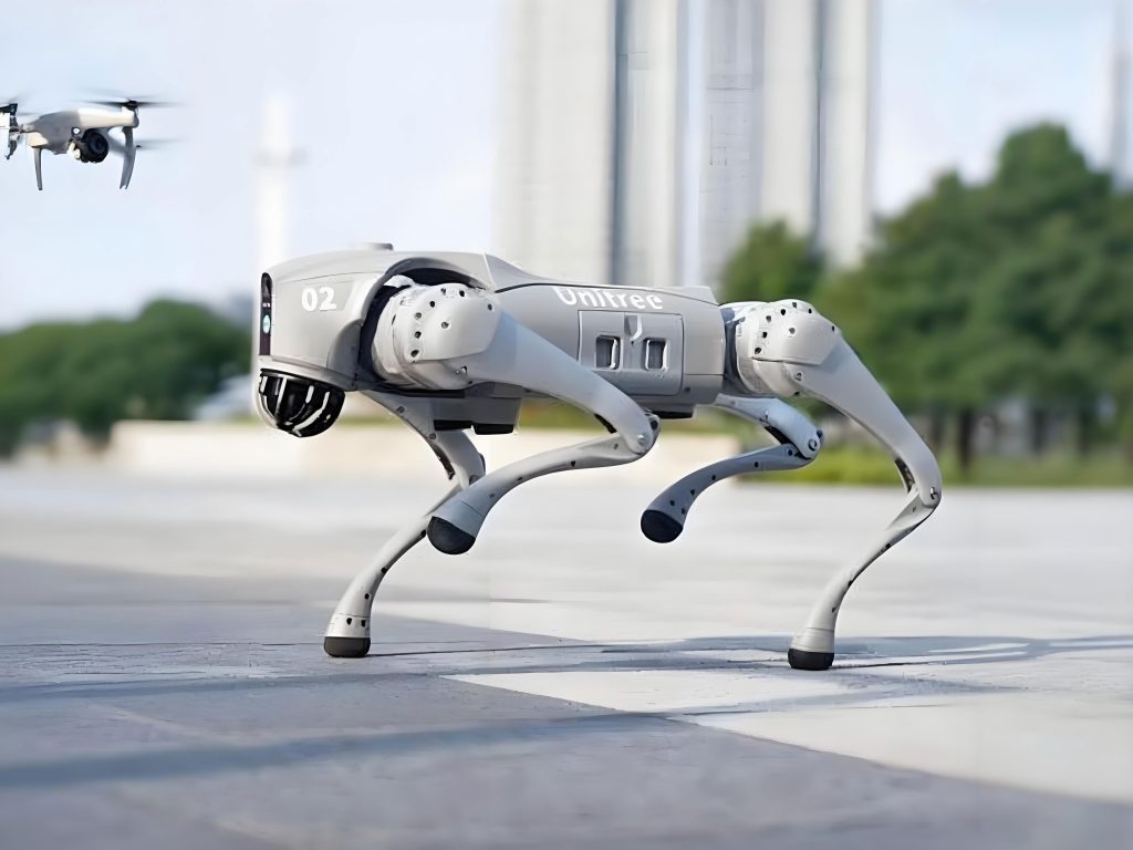
The bionic robot’s design revolves around emulating gecko functions through engineering solutions. I started by decomposing the gecko’s body into modules, as shown in Table 1, which summarizes the bionic functions and their implementation methods. This modular approach allowed me to tackle each aspect systematically, from locomotion to adhesion. The leg joints, for instance, use a combination of servos and linkages to replicate gecko leg movements, enabling walking and climbing gaits. The adhesion system employs a vacuum pump, tubing, solenoid valves, and suckers to generate negative pressure, mimicking the gecko’s toe pad adhesion. Intelligent features like obstacle avoidance and video transmission were added to enhance the bionic robot’s autonomy and utility, making it more than just a climbing machine. Throughout the process, I focused on ensuring that the bionic robot is lightweight, energy-efficient, and controllable, with a total mass of approximately 1.35 kg. The integration of these elements results in a bionic robot that can adapt to flat surfaces and vertical walls, showcasing the potential of bio-inspired design in robotics.
| Bionic Function | Implementation Method | Notes |
|---|---|---|
| Locomotion (Walking/Climbing) | Mechanical linkages, servo motors, microcontroller | Simulates leg joint movements |
| Visual Exploration | Wi-Fi wireless video transmission, real-time camera | Simulates vision system |
| Adhesion | Vacuum pump, solenoid valves, vacuum suckers, tubing | Simulates toe pad hair adhesion via negative pressure |
| Obstacle Avoidance | Ultrasonic sensing modules | Enables real-time detection and response |
| Multi-Terrain Adaptation | Reduction wheel assemblies | Extends mobility on flat surfaces |
| Human-Robot Interaction | Remote Bluetooth control, visual interface | Facilitates practical application and operation |
The adhesion system is critical for this bionic robot, as it enables wall-climbing. I designed a pneumatic circuit using a vacuum generator, tubing, tee connectors, solenoid valves, and vacuum suckers. The circuit allows controlled negative pressure application: when the bionic robot is stationary on a wall, all four suckers are activated; during climbing, at least two suckers maintain adhesion to ensure stability. The adsorption force must counteract the bionic robot’s weight. For a vertical surface, the force calculation is based on vacuum pressure and sucker area. I used rubber vacuum suckers with a diameter of 50 mm, giving an area of approximately 19.63 cm². The adsorption force \(W\) is given by:
$$W = P \cdot S \cdot \frac{1}{f}$$
where \(P\) is the vacuum pressure in kPa, \(S\) is the sucker area in cm², and \(f\) is the safety factor. For vertical hanging, a safety factor of \(f = 8\) is recommended. To prevent slipping, the maximum static friction \(F_{\text{max}}\) must satisfy:
$$F_{\text{max}} = \mu \cdot W \geq mg$$
where \(\mu\) is the coefficient of static friction (taken as 0.45 for rubber on walls), \(m\) is the mass (1.35 kg), and \(g\) is gravitational acceleration (9.8 m/s²). Solving for \(W\):
$$W \geq \frac{mg}{\mu} = \frac{1.35 \times 9.8}{0.45} \approx 29.4 \, \text{N}$$
Thus, the minimum adsorption force is 29.4 N. With at least two suckers active during climbing, the required vacuum pressure per sucker is:
$$P = \frac{W \cdot f}{2S} = \frac{29.4 \times 3.5}{2 \times 19.63} \geq 26.21 \, \text{kPa}$$
To ensure safety, I selected a vacuum pump with a negative pressure of -55 kPa, providing ample adhesion margin. This pneumatic design allows the bionic robot to adhere reliably to walls, simulating gecko-like climbing behavior. The control of solenoid valves is integrated into the bionic robot’s electronic system, enabling automated adhesion management during movement.
The leg joint mechanism is essential for locomotion in this bionic robot. I designed a planar four-bar linkage for each leg, driven by servo motors to emulate gecko leg motions. The thigh joint is controlled by Servo 1, enabling rotation in the XOZ plane for steering and positioning, while the calf joint is driven by Servo 2 through linkages, allowing lifting in the XOY plane for step transitions. The linkage configuration, as shown in Figure 9 (from the original context, but not referenced directly), consists of moving points A, B, C, and D. The degree of freedom \(F\) for this planar mechanism is calculated using Grübler’s formula:
$$F = 3n – 2P_L – P_H$$
where \(n\) is the number of moving links, \(P_L\) is the number of lower pairs, and \(P_H\) is the number of higher pairs. For the four-bar linkage: \(n = 3\), \(P_L = 4\), \(P_H = 0\), so:
$$F = 3 \times 3 – 2 \times 4 – 0 = 1$$
Adding the rotation from Servo 1, the total degrees of freedom per leg is 2, matching the two servos and ensuring deterministic motion. This design allows the bionic robot to execute complex gaits like trotting. I simulated the motion trajectories in ADAMS/View to validate the joint movements. For Servo 1 and Servo 2, I set speeds of 60 rpm (within the servo range of 53–62 rpm) and used Step functions to define alternating motions. The Step function approximates the Heaviside step function with a cubic polynomial:
$$\text{Step}(t, t_0, h_0, t_1, h_1) =
\begin{cases}
h_0 & \text{if } t \leq t_0 \\
y(t) & \text{if } t_0 < t < t_1 \\
h_1 & \text{if } t \geq t_1
\end{cases}$$
where \(y(t) = h_0 + (h_1 – h_0) \left[ \left( \frac{t – t_0}{t_1 – t_0} \right)^2 \left( 3 – 2 \frac{t – t_0}{t_1 – t_0} \right) \right]\). This function controls the servo angles, producing smooth trajectories for points A, B, C, and D. The thigh joint swings in arcs up to 73°, while the calf joint lifts the sucker by about 33.6 mm over a 43° arc, ensuring adequate step height for climbing. The simulations confirmed no interference, indicating reliable mechanical performance.
To assess structural strength, I conducted static finite element analysis on the leg joints using WorkBench. The model, meshed with 51,021 elements and 113,289 nodes, assumed two legs supporting the bionic robot’s weight on flat ground. The support reaction force \(P_0\) is calculated as:
$$P_0 = \frac{G_m}{N \cdot S}$$
where \(G_m = mg = 1.35 \times 9.8 \approx 13.23 \, \text{N}\) is the weight, \(N = 2\) is the number of supporting legs, and \(S = 251 \, \text{mm}^2\) is the contact area per leg. Thus:
$$P_0 = \frac{13.23}{2 \times 251 \times 10^{-6}} \approx 26,354.6 \, \text{Pa}$$
Servo torques were applied: 1.274 N·m for Servo 1 (MG996R) and 0.196 N·m for Servo 2 (MG90S). Constraints included fixed supports at hinge points and pressure loads on contact areas. The analysis revealed maximum von Mises stress of 15.49 MPa at the linkage ends, well below the photopolymer resin’s tensile yield strength of 60 MPa and bending yield strength of 75 MPa. Deformation was minimal, with a maximum displacement of 0.38 mm, ensuring structural integrity for this bionic robot under operational loads.
| Parameter | Value | Description |
|---|---|---|
| Thigh Joint Swing Angle | 0–73° | Arc trajectory for forward/backward motion |
| Calf Joint Lift Height | 33.6 mm | Vertical displacement during stepping |
| Servo Speeds | 60 rpm | Standardized for consistent gait timing |
| Degree of Freedom (per leg) | 2 | Ensures deterministic motion control |
| Maximum Stress in Joints | 15.49 MPa | Below material yield strength for safety |
| Material | Photopolymer Resin | 3D-printed for lightweight and custom geometry |
The control system for this bionic robot is built around an Arduino Mega 2560, which serves as the main microcontroller. I developed a hardware platform integrating voltage regulators (LM2596S), motor drivers (L298N), Bluetooth modules (HC-05), and power terminals. The system is powered by three series-connected 18650 lithium batteries providing 12 V, stepped down to 6 V for the servos using an XL4016E buck converter. This setup ensures stable operation even under high current demands from nine servos. The control flowchart, as implemented, starts with initialization upon power-up, followed by Bluetooth connection for data updates. The bionic robot uses serial communication to execute motion commands. For obstacle avoidance, ultrasonic sensors (HC-SR04) measure distances; if an obstacle is within 20 cm, the bionic robot’s head servo pans to scan for clear paths. If left space is sufficient, it turns left; otherwise, it checks the right side or reverses. On flat ground, if no obstacles are detected, the bionic robot proceeds straight. During wall-climbing, solenoid valves are toggled to maintain adhesion while servos execute a Trot gait for movement.
Gait analysis is crucial for efficient locomotion in this bionic robot. I adopted a Trot gait, a symmetrical pattern where diagonal leg pairs move simultaneously. This gait is energy-efficient and suitable for moderate speeds. As shown in the timing diagram (Figure 4 from original context), for a duty cycle of 0.5, legs are in swing phase for half the cycle and support phase for the other half. At time zero, left front (LF) and right hind (RH) legs swing while right front (RF) and left hind (LH) legs support. At mid-cycle, they switch. This pattern ensures stability by always having at least two legs grounded. The gait is programmed using coordinate outputs: in the first half-cycle, coordinates for LF and RH are sent; in the second half, for RF and LH. This cyclic control enables smooth climbing and walking, making the bionic robot adept at navigating complex surfaces.
Intelligent features enhance this bionic robot’s functionality. The Bluetooth module allows remote control via a smartphone app within a range of 50–80 m, enabling real-time command transmission for direction, speed, and mode changes. The Wi-Fi camera, mounted on the head, streams live video to a mobile device, simulating visual perception for tasks like surveillance. Ultrasonic sensors provide autonomous obstacle detection, with the bionic robot dynamically adjusting its path to avoid collisions. These elements transform the bionic robot from a simple climber into a smart machine capable of interactive operations. In tests, the bionic robot responded promptly to commands and adapted to environmental changes, demonstrating robust intelligence integration.
Experimental validation was conducted to evaluate this bionic robot’s performance. I assembled a prototype using 3D-printed parts, servos, and electronic components. The bionic robot was tested on vertical walls, flat floors, and obstacles. It successfully climbed smooth vertical surfaces using the pneumatic adhesion system, with no slippage observed. The Trot gait enabled stable walking at speeds adjustable via servo control. Obstacle avoidance tests showed that the bionic robot reliably detected and circumvented barriers within 20 cm. Wireless video transmission provided clear real-time footage, useful for remote monitoring. The bionic robot’s battery life lasted approximately 1 hour of continuous operation, sufficient for short missions. These experiments confirmed that the bionic robot meets design goals, offering a practical tool for applications like inspection or rescue. The integration of mechanics, electronics, pneumatics, and intelligence in this bionic robot sets a benchmark for future bio-inspired designs.
In conclusion, my work on this gecko-inspired bionic robot showcases the potential of combining biological principles with engineering innovation. The bionic robot effectively mimics gecko climbing through a pneumatic adsorption system and leg joint mechanisms, while intelligent controls add autonomy and versatility. Key achievements include reliable wall-climbing, adaptive gait control, and seamless human-robot interaction. This bionic robot serves as a platform for further research, such as exploring alternative power sources like solar cells or adding safety features like parachutes for high-altitude falls. The project underscores how bionic robots can advance robotics by emulating nature’s efficiencies, paving the way for more agile and intelligent machines in diverse fields. Through continuous refinement, such bionic robots could revolutionize tasks in hazardous environments, demonstrating the enduring value of bio-inspired design in technology.