
In recent years, the rapid advancement of robotics has led to significant improvements in various fields, enhancing both daily life and industrial efficiency. Among these developments, load-bearing quadruped robots have garnered considerable attention due to their unique locomotion capabilities and exceptional payload capacity. These robots excel in traversing complex terrains and performing critical tasks such as material transport, environmental exploration, and rescue operations. As a researcher in this field, I have focused on designing and simulating a robust quadruped robot that combines stability, high load-bearing capacity, and environmental adaptability. This article delves into the comprehensive process of developing such a robot, emphasizing structural design, kinematic analysis, gait planning, and stress evaluation. Through this work, I aim to contribute to the growing body of knowledge on quadruped robots and pave the way for practical applications in demanding scenarios.
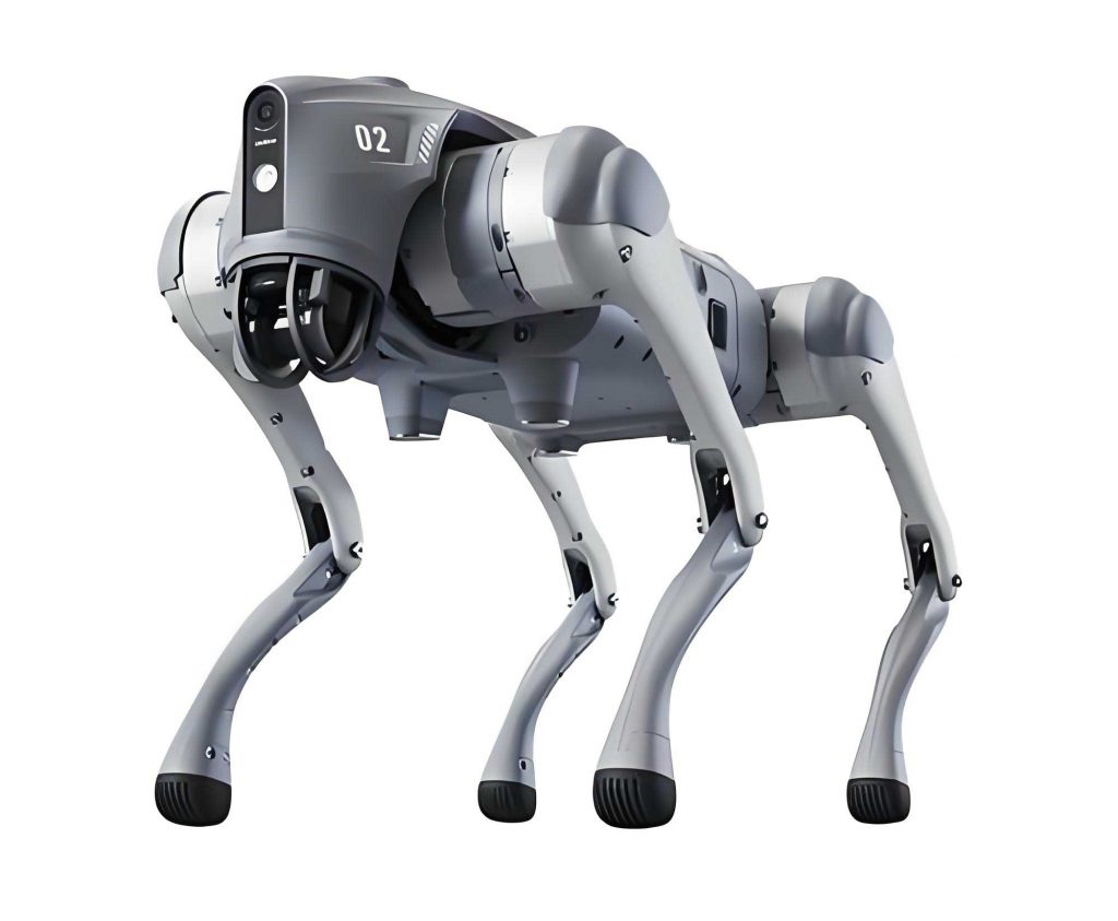
The design of this quadruped robot, often referred to as a robot dog, draws inspiration from biological systems to achieve optimal performance. The mechanical structure was meticulously crafted to balance lightweight properties with durability, ensuring that the robot can handle substantial loads while maneuvering through uneven environments. Key considerations included the leg configuration, joint arrangement, and overall body architecture. For instance, the body employs a double-layer design that not only reduces mass but also provides a secure compartment for control systems and electronics. Each leg features a multi-degree-of-freedom mechanism, enabling complex movements and enhanced flexibility. This biomimetic approach allows the quadruped robot to mimic the efficient locomotion of animals, such as spiders, which are known for their stability and adaptability. In the following sections, I will elaborate on the detailed design choices and analytical methods used to bring this robot dog to life.
To ensure the robot dog’s movements are precise and controllable, I conducted a thorough kinematic analysis using the Denavit-Hartenberg (D-H) parameter method. This involved defining coordinate systems for each joint and deriving transformation matrices to describe the relationships between them. For a single leg of the quadruped robot, I established three main joints: the base, thigh, and foot. The D-H parameters, including joint angles, link lengths, offsets, and twist angles, were tabulated to facilitate the computation of forward and inverse kinematics. The forward kinematics analysis determines the end-effector position based on given joint angles, while the inverse kinematics solves for the joint angles required to achieve a desired end-effector pose. This is crucial for planning the robot’s gait and ensuring accurate foot placement during operation. Below, I present the D-H parameters table and the corresponding transformation matrices.
| Joint | θ (rad) | a (mm) | d (mm) | α (rad) |
|---|---|---|---|---|
| 1 | θ₁ | 0 | 0 | 0 |
| 2 | θ₂ | l₁ | 0 | -π/2 |
| 3 | θ₃ | l₂ | 0 | 0 |
The transformation matrix between adjacent joints is given by the standard D-H formula:
$$ T_i = \begin{bmatrix}
\cos\theta_i & -\sin\theta_i \cos\alpha_i & \sin\theta_i \sin\alpha_i & a_i \cos\theta_i \\
\sin\theta_i & \cos\theta_i \cos\alpha_i & -\cos\theta_i \sin\alpha_i & a_i \sin\theta_i \\
0 & \sin\alpha_i & \cos\alpha_i & d_i \\
0 & 0 & 0 & 1
\end{bmatrix} $$
For the base joint (joint 1), the transformation matrix \( T_{01} \) is:
$$ T_{01} = \begin{bmatrix}
\cos\theta_1 & -\sin\theta_1 & 0 & 0 \\
\sin\theta_1 & \cos\theta_1 & 0 & 0 \\
0 & 0 & 1 & 0 \\
0 & 0 & 0 & 1
\end{bmatrix} $$
For the thigh joint (joint 2), the matrix \( T_{12} \) becomes:
$$ T_{12} = \begin{bmatrix}
\cos\theta_2 & -\sin\theta_2 & 0 & l_1 \\
0 & 0 & -1 & 0 \\
\sin\theta_2 & \cos\theta_2 & 0 & 0 \\
0 & 0 & 0 & 1
\end{bmatrix} $$
And for the foot joint (joint 3), \( T_{23} \) is expressed as:
$$ T_{23} = \begin{bmatrix}
\cos\theta_3 & -\sin\theta_3 & 0 & l_2 \\
\sin\theta_3 & \cos\theta_3 & 0 & 0 \\
0 & 0 & 1 & 0 \\
0 & 0 & 0 & 1
\end{bmatrix} $$
The overall transformation from the base to the end-effector is obtained by multiplying these matrices: \( T_{03} = T_{01} T_{12} T_{23} \). This allows me to compute the position and orientation of the foot relative to the body frame. For inverse kinematics, given a target end-effector position \( (x, y, z) \), I derive the joint angles using geometric relationships. For example, the angle \( \theta_1 \) at the ankle joint can be found as:
$$ \theta_1 = \arctan2(y, x) – \arctan2(l_2, l_1 + d) $$
where \( d = \sqrt{x^2 + y^2} \). Similarly, \( \theta_2 \) and \( \theta_3 \) are calculated using:
$$ \theta_3 = \arccos\left( \frac{l_1^2 + l_2^2 – R^2}{2 l_1 l_2} \right) $$
and
$$ \theta_2 = \arctan2(z – l_1 \cos\theta_1, d – l_2 \cos\theta_1) – \arctan2(l_2 \sin\theta_3, l_1 + l_2 \cos\theta_3) $$
with \( R = \sqrt{(l_1 + d – l_2 \cos\theta_1 – z)^2 + (l_2 \sin\theta_1)^2} \). These equations enable precise control of the robot dog’s leg movements, which is essential for stable gait execution.
Another critical aspect of the quadruped robot design is the determination of its degrees of freedom (DOF). Using the Kutzbach-Grubler formula, I calculated the total DOF for the robot dog to ensure it possesses sufficient mobility for complex tasks. The formula is given by:
$$ F = 6(n – g – 1) + \sum_{i=1}^{g} f_i $$
where \( F \) is the number of degrees of freedom, \( n \) is the number of movable links, \( g \) is the number of joints, and \( f_i \) is the DOF provided by the i-th joint. For this quadruped robot, with four legs each having three joints, the calculation yields a total of 6 DOF for the entire system. These include pitch, roll, and yaw rotational freedoms, as well as linear movements in the forward-backward, left-right, and up-down directions. This high level of mobility allows the robot dog to adapt to various terrains and perform dynamic maneuvers, such as turning and climbing, while maintaining balance under load.
Gait planning is vital for the efficient locomotion of the quadruped robot. I adopted the Creep crawling gait, as proposed by Marc Raibert, to coordinate the leg movements during walking. This gait involves alternating the lifting and placing of legs in a specific sequence to ensure stability and minimize energy consumption. The Creep gait can be divided into several phases, where the robot shifts its weight and moves one leg at a time. For instance, in the initial phase, the robot stands on three legs while lifting the fourth, and then it advances by swinging the lifted leg forward. The displacement per gait cycle can be quantified using geometric analysis. If the leg swing is modeled as a line segment of length \( L \), the total displacement \( X \) per cycle is:
$$ X = 2 \times L \times \sin(45^\circ) = \sqrt{2} L $$
This formula ensures that the robot dog moves smoothly and predictably, which is crucial for load-bearing applications where sudden movements could compromise stability. The table below summarizes the key parameters used in the gait planning for this quadruped robot.
| Parameter | Symbol | Value | Unit |
|---|---|---|---|
| Leg Swing Length | L | 150 | mm |
| Displacement per Cycle | X | ~212 | mm |
| Gait Cycle Time | T | 2.0 | s |
| Number of Phases | N | 4 | – |
To validate the structural integrity of the robot dog, I performed static stress analysis using Solidworks Simulation. This involved applying loads to various components and evaluating the stress distribution and deformation. The primary goal was to ensure that all parts could withstand the operational forces without failure, especially under maximum load conditions. For instance, the foot component showed stress concentration at the root, with a maximum von Mises stress of 39.610 MPa, which is within the safe limits of the PLA material used (yield strength of 50 MPa). Similarly, the knee joint exhibited stresses up to 15.937 MPa around the bolt holes, while the hip joint and connecting rod had maximum stresses of 6.661 MPa and 32.580 MPa, respectively. These values indicate that the design is robust and capable of handling the intended loads. The table below provides a summary of the stress analysis results for key components of the quadruped robot.
| Component | Max Von Mises Stress (MPa) | Critical Location | Safety Factor |
|---|---|---|---|
| Foot | 39.610 | Root | 1.26 |
| Knee Joint | 15.937 | Bolt Holes | 3.14 |
| Hip Joint | 6.661 | Bolt Holes | 7.50 |
| Connecting Rod | 32.580 | Mid-Section | 1.53 |
Additionally, I analyzed the leg assembly in different configurations: support, contraction, and extension states. In the support state, where the foot and knee form a 60-degree angle, the maximum stress was 4.392 MPa, with noticeable bending at 1.3 MPa. For the contraction state (30-degree angle), the stress was minimal at 1.504 MPa, and no significant deformation occurred. In the extension state (120-degree angle), the stress reached 3.923 MPa, but it remained below the material’s yield strength. These analyses confirm that the robot dog’s legs are designed to maintain structural integrity across various operating conditions, which is essential for reliable performance in real-world applications.
In conclusion, the design and simulation of this load-bearing quadruped robot demonstrate a holistic approach to achieving stability, payload capacity, and adaptability. Through kinematic analysis, I established precise control over the robot’s movements, while the DOF calculation ensured sufficient mobility. The Creep gait planning enabled efficient locomotion, and the stress analysis verified the structural robustness of all components. This work not only provides a solid foundation for building a physical prototype but also highlights the potential of quadruped robots in demanding environments. Future efforts will focus on optimizing the design for higher loads and integrating advanced sensors for autonomous navigation. As robotics continues to evolve, I believe that robot dogs like this one will play an increasingly vital role in industries such as logistics, search and rescue, and exploration.
Reflecting on the entire process, I am confident that the methodologies employed here—ranging from D-H parameter-based kinematics to finite element analysis—can be adapted to other robotic systems. The iterative design and simulation phases were instrumental in identifying potential issues and refining the robot dog’s performance. Moreover, the use of biomimetic principles underscores the value of learning from nature to solve engineering challenges. As I move forward, I plan to explore dynamic simulations and real-world testing to further validate the capabilities of this quadruped robot. Ultimately, the goal is to contribute to the development of intelligent, versatile robots that can assist humans in a wide array of tasks, pushing the boundaries of what is possible in robotics.