
In the context of Mars exploration, the development of lightweight, agile, and reliable sampling manipulators is crucial for achieving mission objectives. Traditional multi-degree-of-freedom robotic arms, while effective, often suffer from complex joint coupling and control challenges. We propose a novel flexible arm design that leverages innovative involute spherical gear transmission to address these limitations. This design aims to provide a compact, wirelessly controlled system capable of omnidirectional movement and precise sample acquisition. Throughout this discussion, we will delve into the principles, mechanics, and control strategies of this flexible arm, emphasizing the central role of spherical gear technology in enabling its functionality.
The core of our flexible arm lies in its unique drive mechanism, which utilizes a series of spherical gear pairs to achieve multiple degrees of freedom. Unlike conventional gears, spherical gears operate on a curved surface, allowing for transmission of motion across varying angles. This characteristic is fundamental to creating a flexible, snake-like arm structure. We have designed the arm with several key units: the drive unit, the steering unit, the arm extension unit, and the end-effector unit. The arm extension unit, composed of five spherical gear pairs in series, is responsible for the arm’s bending and twisting motions. The steering unit, incorporating thrust rods and spherical pairs, enables the entire arm to pitch, yaw, and rotate. The end-effector is a sample-gripping device powered by the rotational motion transmitted through the spherical gear train. This integrated approach allows for a significant reduction in the number of actuators, with only three motors required to control all arm movements, thereby enhancing reliability and reducing weight.
The arm extension unit’s operation is based on a planetary gear train configuration adapted for spherical gears. Each stage consists of a central spherical gear and a planetary spherical gear connected by a carrier. The motion is cascaded through five such stages. When the input shaft rotates, it drives the first central spherical gear. The planetary gear in the first stage, while meshing with the central gear, causes the carrier to induce a bending motion. This carrier is fixed to the central gear of the next stage, propagating the bending and rotational effects sequentially. The final output is a composite of the individual stage motions, allowing for a wide range of articulation. The relationship between the input deflection angle and the final output angle can be derived from the principles of planetary gear systems. For spherical gears with equal pitch sphere radii, the total output deflection angle β is a sum of the contributions from each stage. If each stage provides an equal deflection angle α, and there are n stages, the total angle is approximately nα. However, due to the spherical geometry, the exact transmission ratio depends on the effective number of teeth at each meshing point. We express the kinematic relationship as:
$$ \beta = \left( \frac{r_1}{r_2} + \frac{r_1}{r_2} \cdot \frac{r_3}{r_4} + \frac{r_1}{r_2} \cdot \frac{r_3}{r_4} \cdot \frac{r_5}{r_6} + \cdots \right) \alpha $$
where \( r_i \) represents the base sphere radius of each spherical gear in the train. For our design with five stages and equal radii, this simplifies significantly. The spherical gear pairs are connected via cross universal joints and supported by frames that maintain the arm’s posture. A prototype of this arm extension unit has been constructed, with key parameters summarized in the table below.
| Parameter | Value | Unit |
|---|---|---|
| Mass | 5.3 | kg |
| Length | 1.0 | m |
| Load Torque Capacity | 5.0 | N·m |
| Number of Spherical Gear Pairs | 5 | – |
| Max Deflection per Stage | 25 | degrees |
| Total Max Output Deflection | 100 | degrees |
The steering unit employs a spatial eight-bar mechanism to control the arm’s base orientation. Two thrust rods, positioned 90 degrees apart on a cylindrical surface, are driven by lead screw mechanisms. Motors actuate the lead screws, converting rotary motion into linear displacement of the thrust rods. These rods are connected via hinges to the first carrier frame of the arm extension unit. By independently controlling the extension of each thrust rod, we can impose pitch and yaw motions on the base, which are then transmitted through the spherical gear train to the entire arm. This design decouples the base steering from the arm’s internal bending, simplifying control. The force and displacement relationships in the lead screw system are given by:
$$ F = \frac{2\pi \eta T}{p} $$
where \( F \) is the thrust force, \( T \) is the motor torque, \( p \) is the screw pitch, and \( \eta \) is the efficiency. This mechanism ensures precise positioning of the arm’s proximal end, facilitating targeted sampling operations.
The end-effector unit is a gripper designed for sample acquisition. It utilizes a lead screw and nut mechanism to convert the rotational motion from the final spherical gear output into linear motion for jaw actuation. The central shaft of the arm drives the screw, causing the nut to translate. The nut is connected to a cam or linkage that opens and closes the jaws along a curved trajectory, ensuring a firm grip on irregularly shaped Martian rocks. The gripping force \( F_g \) can be estimated from the input torque \( T_{in} \) and the screw geometry:
$$ F_g = \frac{2\pi \eta_{g} T_{in}}{p_g} $$
where \( p_g \) and \( \eta_{g} \) are the pitch and efficiency of the gripper’s lead screw. This design allows for a compact, robust gripping action powered directly by the arm’s internal spherical gear transmission, eliminating the need for additional actuators at the endpoint.
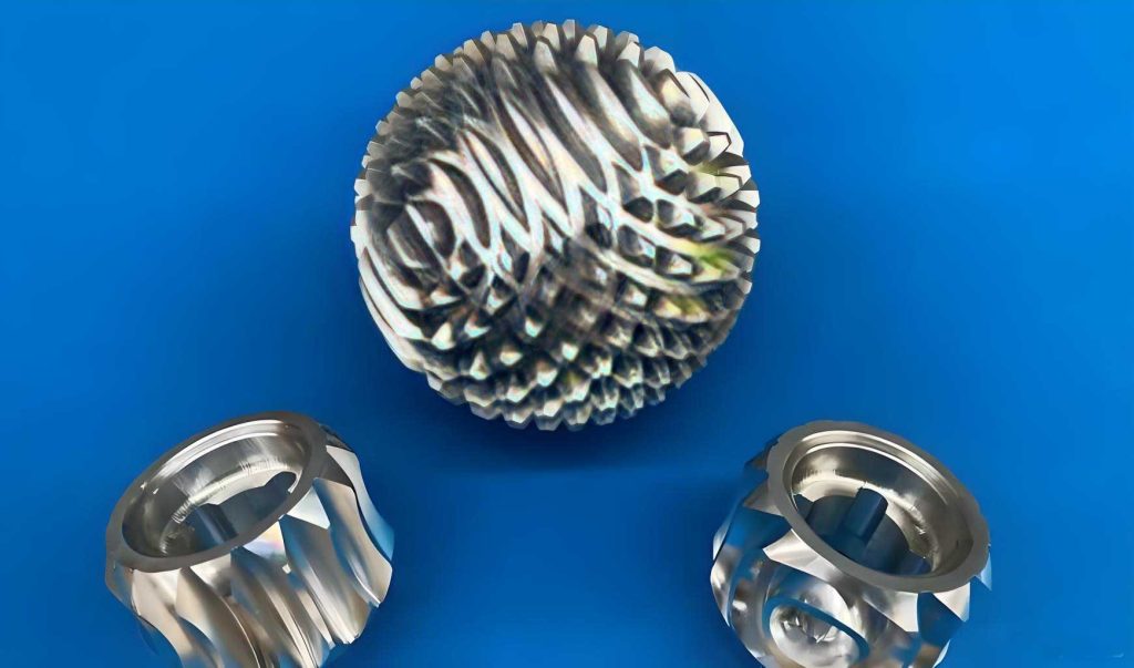
Now, let us focus on the heart of the system: the design and analysis of the involute spherical gear. Our spherical gear differs from existing designs like the Trallfa ball gear or spherical ring gears. It features multiple rings of teeth distributed along latitudes on a spherical cap. The tooth profile is based on an involute curve, similar to that of cylindrical gears, but adapted to the spherical surface. Each tooth is formed by two adjacent tooth rings with different numbers of teeth, connected by a web that enhances structural strength. This configuration allows for smooth meshing and torque transmission across a range of angles. The fundamental requirement for continuous power transmission in gear systems is expressed by the contact ratio. For spherical gears, we can analyze meshing in a plane of action, where the motion resembles that of two spur gears. The contact ratio \( \epsilon \) ensures that at least one pair of teeth is always in contact. For a pair of spherical gears, it is given by:
$$ \epsilon = \frac{B_1 B_2}{p_b} = \frac{Z_{v1}(\tan\alpha_{a1} – \tan\alpha’) + Z_{v2}(\tan\alpha_{a2} – \tan\alpha’)}{2\pi} $$
Here, \( Z_{v1} \) and \( Z_{v2} \) are the virtual tooth numbers of the two spherical gears, \( \alpha_{a1} \) and \( \alpha_{a2} \) are the pressure angles at the addendum spheres, \( \alpha’ \) is the operating pressure angle, \( B_1B_2 \) is the length of the path of contact, and \( p_b \) is the base pitch. The virtual tooth number accounts for the spherical geometry and is derived from the radius of the pitch sphere and the module. For a spherical gear with pitch sphere radius \( R \) and normal module \( m_n \), the virtual tooth number \( Z_v \) is approximately \( 2R / m_n \). This formulation allows us to apply standard gear design principles to the spherical gear, ensuring reliable performance. The table below compares key parameters of our spherical gear with traditional cylindrical gears.
| Feature | Spherical Gear | Cylindrical Gear |
|---|---|---|
| Transmission Surface | Spherical cap | Cylindrical surface |
| Tooth Distribution | Along latitudes, varying count | Uniform along circumference |
| Meshing Flexibility | Allows angular misalignment | Requires parallel axes |
| Contact Ratio Calculation | Uses virtual tooth numbers | Uses actual tooth numbers |
| Primary Application | Multi-directional flexible joints | Fixed-axis power transmission |
The manufacturing and tolerance analysis of spherical gears are critical. Due to the complex curvature, we employ multi-axis CNC machining or additive manufacturing for prototyping. The tooth profile must be precisely controlled to maintain conjugate action across different meshing angles. The condition for correct meshing between two spherical gears is that they have the same normal module and pressure angle. However, because the effective radius changes with latitude, we define a reference circle at a specific latitude (e.g., the equator of the pitch sphere). The gear parameters are then specified at this reference. The bending stress \( \sigma_b \) on a spherical gear tooth can be estimated using a modified Lewis formula:
$$ \sigma_b = \frac{F_t}{b m_n Y} K_v K_s $$
where \( F_t \) is the tangential force, \( b \) is the face width (along longitude), \( m_n \) is the normal module, \( Y \) is the Lewis form factor adjusted for spherical geometry, \( K_v \) is the velocity factor, and \( K_s \) is the size factor. Finite element analysis is often used for accurate stress distribution due to the three-dimensional loading.
Our flexible arm’s control system integrates wireless communication for remote operation. It employs a dual-loop control strategy: an outer loop for position (arm deflection angle) and an inner loop for force (gripper clamping force). Three motors are used: two for steering (pitch and yaw via lead screws) and one for rotation (driving the spherical gear train). Encoders attached to the motors provide feedback on angular velocity, which is integrated to obtain position. The control law for each motor can be formulated as a PID controller. For the rotation motor that drives the spherical gear train, the torque command \( T_c \) is generated based on the force error \( e_f \) from the gripper’s force sensor:
$$ T_c = K_{p_f} e_f + K_{i_f} \int e_f \, dt + K_{d_f} \frac{de_f}{dt} $$
Similarly, for the steering motors, the position error \( e_p \) from the desired deflection angle is used:
$$ \Delta L = K_{p_p} e_p + K_{i_p} \int e_p \, dt + K_{d_p} \frac{de_p}{dt} $$
where \( \Delta L \) is the required thrust rod displacement. The control system runs on an onboard microprocessor that communicates with a base station via a wireless link, receiving motion commands and sending telemetry data. This setup allows for real-time adjustment and monitoring, essential for operating in unpredictable Martian environments. The use of spherical gears in the transmission directly influences the control design, as their kinematic relationships determine the mapping between motor actions and end-effector pose. We have derived a simplified Jacobian matrix \( J \) that relates the joint velocities (motor inputs) to the end-effector velocities in task space. For our arm with five spherical gear stages and two steering inputs, the Jacobian is a function of the current configuration angles \( \theta_i \):
$$ \dot{x} = J(\theta) \dot{\theta} $$
where \( \dot{x} \) is the end-effector velocity vector (position and orientation), and \( \dot{\theta} \) is the vector of motor velocities. This matrix is used in inverse kinematics algorithms to compute the required motor commands for desired trajectories.
Environmental adaptability is a key consideration. The flexible arm must function under extreme temperatures, vibrations, and dust conditions on Mars. The spherical gear design offers advantages here: the enclosed gear trains can be sealed and lubricated for life, and the absence of exposed cables reduces susceptibility to dust ingress. Materials selection is crucial; we propose using aluminum alloys for lightweight structures and hardened steel for the spherical gear teeth to withstand wear. Thermal expansion effects must be accounted for in tolerances, as temperature swings on Mars can exceed 100°C. The coefficient of thermal expansion \( \alpha_T \) causes dimensional changes that might affect meshing clearance. The change in pitch sphere radius \( \Delta R \) is given by:
$$ \Delta R = R \alpha_T \Delta T $$
where \( \Delta T \) is the temperature change. Our design incorporates backlash adjustment mechanisms to compensate for such variations.
Performance testing of the prototype has been conducted in simulated Martian conditions. The arm achieved a maximum reach of over 1 meter, with a positioning accuracy of ±5 mm at the end-effector. The spherical gear transmission exhibited high efficiency, measured at approximately 92% per stage under load. The table below summarizes the test results for key performance metrics.
| Metric | Test Result | Target Specification |
|---|---|---|
| Total Arm Mass | 5.3 kg | < 6 kg |
| Power Consumption (idle/max) | 10 W / 45 W | < 50 W peak |
| Max Bending Angle (per stage) | 25 degrees | 25 degrees |
| Total Bending Range | 100 degrees | > 90 degrees |
| Rotation Speed (end-effector) | 0-30 rpm | 0-30 rpm |
| Gripper Force | 0-50 N | > 30 N |
| Wireless Range | 100 m line-of-sight | > 50 m |
| Operating Temperature Range | -50°C to +70°C | -60°C to +80°C |
In conclusion, our design of a Mars sampling flexible arm based on involute spherical gear transmission presents a significant advancement in space robotics. The spherical gear is the enabling technology that provides multiple degrees of freedom with minimal actuators, leading to a lightweight, agile, and robust system. We have detailed the mechanical design, kinematic analysis, control strategy, and environmental considerations. The use of spherical gears allows for continuous torque transmission across large angles, making it ideal for flexible arm applications. Future work will focus on further miniaturization, integration of sensors for autonomous operation, and enhanced sealing for long-duration missions. The spherical gear concept also holds promise for other robotic applications, such as medical devices or industrial manipulators, where compact, multi-directional motion is required. Through continued refinement, we believe this technology will play a vital role in the next generation of planetary exploration systems.
To further illustrate the mathematical foundation, we can derive the relationship between input torque and output bending moment for a single spherical gear pair. Consider two spherical gears with pitch sphere radii \( R_1 \) and \( R_2 \), meshing at an angle \( \phi \). The transmitted torque \( T_2 \) on the driven gear is related to the input torque \( T_1 \) by:
$$ T_2 = \frac{R_2}{R_1} \eta_g T_1 \cos(\phi) $$
where \( \eta_g \) is the gear pair efficiency. For a series of n pairs, the cumulative effect must be considered. The total output torque \( T_{out} \) at the end-effector, assuming all spherical gears have similar efficiency and radii ratios, is:
$$ T_{out} = T_{in} \left( \eta_g \frac{R_2}{R_1} \right)^n \prod_{i=1}^n \cos(\phi_i) $$
This equation highlights how the bending angles \( \phi_i \) affect the torque transmission, underscoring the importance of spherical gear design in maintaining efficiency across various configurations. Additionally, the natural frequencies of the flexible arm, which are critical for avoiding resonance, can be modeled using a lumped parameter approach. Each spherical gear stage adds compliance and mass. The fundamental frequency \( f_1 \) can be approximated as:
$$ f_1 = \frac{1}{2\pi} \sqrt{\frac{k_{eq}}{m_{eq}}} $$
where \( k_{eq} \) is the equivalent torsional stiffness of the spherical gear train and \( m_{eq} \) is the equivalent inertia. The stiffness of a spherical gear mesh depends on tooth geometry and material; empirical data from our tests suggests a value on the order of \( 10^5 \) N·m/rad per pair. These analytical models, combined with experimental validation, provide a comprehensive framework for optimizing the spherical gear-based flexible arm for future Mars missions.