
The pursuit of high-performance, reliable power transmission in demanding applications such as heavy-duty robotics, aerospace actuators, and marine propulsion systems has intensified the focus on precision heavy-load reducers. Among various gear technologies, the rotary vector reducer stands out for its exceptional combination of high reduction ratio, compact size, robust load-carrying capacity, and superior torsional rigidity. This article, based on extensive research, delves into the dynamic characteristics of a heavy-load rotary vector reducer, specifically the RV-550E model. We establish a comprehensive multi-degree-of-freedom dynamics model, analyze its natural frequencies, and perform a detailed sensitivity analysis. The primary goal is to elucidate the influence of key component parameters on the system’s vibrational behavior, thereby providing a foundational theoretical framework for structural optimization and avoiding resonant conditions during operation.
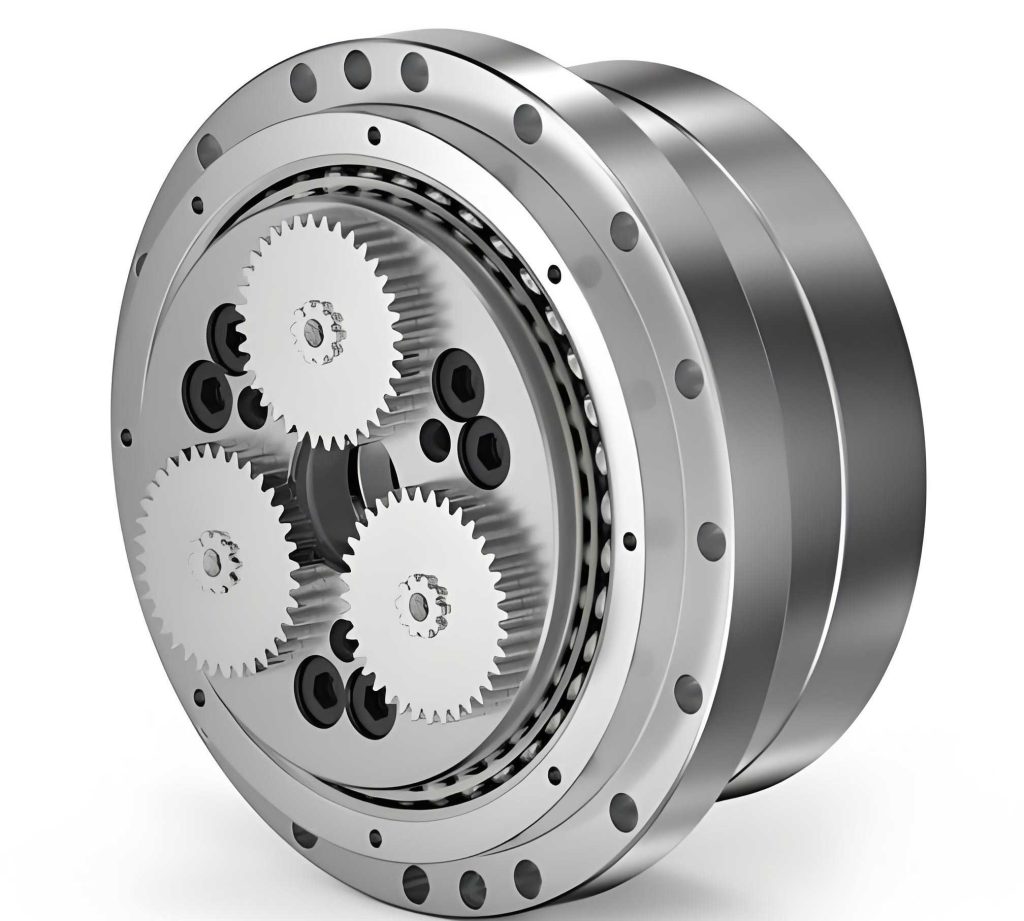
The operational excellence of a rotary vector reducer stems from its unique two-stage design. The primary stage consists of a planetary gear train, while the secondary stage employs a cycloidal-pin gear mechanism. This configuration, where the crankshafts are shared between stages and supported by a central disc, creates a closed planetary system. The kinematic principle involves the sun gear driving the planetary gears, which are rigidly connected to the crankshafts. The eccentric motion of the crankshafts engages the cycloidal gears with the stationary pin gear housing (or shell), causing the cycloidal gears to undergo a compound motion of revolution and reverse rotation. This reverse rotation is transmitted through the crankshafts to the planet carrier, which serves as the output. Understanding the complex interactions within this assembly is crucial for predicting and controlling its dynamic response.
To accurately capture the dynamic behavior of the heavy-load rotary vector reducer, a 16-degree-of-freedom (16-DOF) lumped-parameter model is developed. This modeling approach requires several simplifying yet practical assumptions to ensure analytical tractability while retaining physical fidelity:
- All components have uniform mass distribution, with their geometric centers coinciding with their centers of mass.
- Time-varying meshing stiffnesses (for both involute and cycloidal-pin pairs) and bearing stiffnesses are represented by their mean values, modeled as equivalent linear springs.
- The force between the cycloidal gear and the pin is considered a concentrated stress, with the equivalent meshing angle $\beta$ calculated using established methods.
- Frictional and damping effects are neglected, and the crankshaft’s bending deformation is ignored as its stiffness significantly exceeds that of the supporting bearings.
- Manufacturing and assembly errors are not considered in this fundamental model.
The model accounts for all significant motions: the rotational vibrations of the sun gear, planet carrier, pin gear housing, two cycloidal gears, three planetary gears, and three crankshafts. Additionally, it includes the translational (orbital) motions of the two cycloidal gears and the three crankshafts as they revolve around the central axis. The generalized displacements along the lines of action for the torsional degrees are defined as follows:
$$
\begin{aligned}
u_s &= r_s \theta_s, \quad u_{pi} = r_p \theta_{pi}, \quad u_{hi} = a \theta_{hi}, \\
u_{cj} &= r_h \theta_{cj}, \quad u_o = r_h \theta_o, \quad u_r = r_r \theta_r,
\end{aligned}
$$
where $\theta_s$, $\theta_{pi}$, $\theta_{hi}$, $\theta_{cj}$, $\theta_o$, $\theta_r$ are the angular displacement perturbations for the sun gear, the i-th planetary gear ($i=1$~$3$), the i-th crankshaft, the j-th cycloidal gear ($j=1$~$2$), the planet carrier (output), and the pin gear housing, respectively. The parameters $r_s$, $r_p$, $a$, $r_h$, and $r_r$ are the pitch circle radius of the sun gear, the pitch circle radius of the planetary gear, the eccentricity, the distribution radius of the crankshafts, and the distribution radius of the pins, respectively.
The relative displacements between components in their respective motion directions are critical for formulating the stiffness forces. The relative displacement between a crankshaft and a cycloidal gear projected onto the cycloidal gear’s orbital direction is:
$$
\Delta c_{ij} = u_{hi} – \eta_{hi} \cos(\phi_i + (j-1)\pi) + u_{cj} \cos(\phi_i + (j-1)\pi) – \eta_{cj}.
$$
The same relative displacement projected onto the crankshaft’s translational direction is:
$$
\Delta c’_{ij} = u_{cj} – \eta_{cj} \cos(\phi_i + (j-1)\pi) + u_{hi} \cos(\phi_i + (j-1)\pi) – \eta_{hi}.
$$
The displacement along the meshing line between a cycloidal gear and the pin gear housing is:
$$
\Delta cc_{jr} = u_{cj} + \eta_{cj} \cos \beta – u_r.
$$
Applying Newton’s second law, the system of 16 second-order differential equations is derived. The governing matrix equation for free, undamped vibration is:
$$
\mathbf{M}\ddot{\mathbf{X}} + \mathbf{K}\mathbf{X} = \mathbf{0},
$$
where $\mathbf{M}$ is the mass/inertia matrix, $\mathbf{K}$ is the stiffness matrix, and $\mathbf{X}$ is the vector of generalized coordinates. The natural frequencies $\omega_r$ and corresponding mode shapes $\phi_r$ are obtained by solving the associated eigenvalue problem:
$$
( -\omega_r^2 \mathbf{M} + \mathbf{K} )\phi_r = \mathbf{0}.
$$
The analysis is performed on the RV-550E heavy-duty rotary vector reducer. Key geometric and dynamic parameters are summarized in the tables below.
| Parameter | Symbol | Value |
|---|---|---|
| Number of Sun Gear Teeth | $Z_s$ | 14 |
| Number of Planetary Gear Teeth | $Z_p$ | 42 |
| Number of Cycloidal Gear Teeth | $Z_c$ | 59 |
| Number of Pins | $Z_r$ | 60 |
| Module | $m$ | 3 mm |
| Pressure Angle | $\alpha$ | 20° |
| Eccentricity | $a$ | 2.2 mm |
| Sun Gear Base Radius | $r_s$ | 21 mm |
| Planetary Gear Base Radius | $r_p$ | 63 mm |
| Crankshaft Distribution Radius | $r_h$ | 84 mm |
| Pin Distribution Radius | $r_r$ | 165 mm |
| Component | Mass (kg) | Moment of Inertia (kg·m²) | Stiffness Parameter | Value |
|---|---|---|---|---|
| Sun Gear | $m_s=5.083$ | $I_s=2.43\times10^{-3}$ | Torsional Stiffness, $k_s$ | $3.62\times10^6$ N·m/rad |
| Planetary Gear | $m_p=1.326$ | $I_p=2.87\times10^{-3}$ | Involute Mesh Stiffness, $k_{sp}$ | $3.92\times10^9$ N/m |
| Crankshaft | $m_h=1.761$ | $I_h=4.73\times10^{-4}$ | Torsional Stiffness, $k_h$ | $1.56\times10^6$ N·m/rad |
| Cycloidal Gear | $m_c=8.562$ | $I_c=0.14$ | Cycloidal-Pin Mesh Stiffness, $k_{cr}$ | $3.15\times10^{10}$ N/m |
| Planet Carrier | $m_o=42.96$ | $I_o=0.513$ | Support Bearing Stiffness, $k_{oh}$ | $3.15\times10^8$ N/m |
| Pin Gear Housing | $m_r=51.209$ | $I_r=1.986$ | Torsional Stiffness, $k_r$ | $1.0\times10^{10}$ N·m/rad |
| — | — | — | Arm Bearing Stiffness, $k_{hc}$ | $1.18\times10^8$ N/m |
Solving the eigenvalue problem yields the first six natural frequencies of the rotary vector reducer, as listed in Table 3. Lower-order modes are of primary concern as they are most susceptible to excitation from common input frequencies and mesh frequencies.
| Mode Order | 1 | 2 | 3 | 4 | 5 | 6 |
|---|---|---|---|---|---|---|
| Natural Frequency (Hz) | 305 | 830 | 864 | 1686 | 1739 | 1750 |
A distinctive aspect of modeling heavy-load rotary vector reducers is the consideration of the pin gear housing’s flexibility. Contrary to models for smaller reducers where the housing is assumed rigid, in heavy-duty applications, the housing experiences significant loads and its stiffness can influence system dynamics. We investigate the effect of the pin gear housing’s torsional stiffness ($k_r$) on the first three natural frequencies. The relationship is plotted and reveals critical design insights: the first natural frequency increases with $k_r$ but saturates once $k_r$ exceeds approximately $2 \times 10^7$ N·m/rad. The second natural frequency shows a similar trend, saturating near $8 \times 10^7$ N·m/rad. Notably, the third natural frequency remains entirely unaffected by changes in $k_r$, indicating it corresponds to a translational vibration mode largely decoupled from the housing’s torsion. This analysis provides a clear guideline: to ensure stable, predictable low-frequency dynamics, the design of the pin gear housing for a heavy-load rotary vector reducer should target a torsional stiffness above $2 \times 10^7$ N·m/rad, balancing performance with material and manufacturing cost.
To systematically guide the optimization of the rotary vector reducer’s dynamic performance and avoid resonance, a sensitivity analysis is indispensable. It quantifies how perturbations in system parameters (masses, inertias, stiffnesses) affect the natural frequencies. The direct differentiation method is employed for its clarity and computational efficiency. For an undamped system, the sensitivity of the r-th natural frequency $\omega_r$ with respect to a generic parameter $p_m$ is:
$$
\frac{\partial \omega_r}{\partial p_m} = – \frac{1}{2\omega_r} \left( \omega_r^2 \phi_r^T \frac{\partial \mathbf{M}}{\partial p_m} \phi_r – \phi_r^T \frac{\partial \mathbf{K}}{\partial p_m} \phi_r \right).
$$
Specific formulas for the sensitivity with respect to mass/inertia matrix elements $m_{ij}$ and stiffness matrix elements $k_{ij}$ are derived as:
$$
\frac{\partial \omega_r}{\partial m_{ij}} = \begin{cases}
-\omega_r \varphi_{ir} \varphi_{jr}, & i \neq j \\
-\frac{1}{2} \omega_r \varphi_{ir}^2, & i = j
\end{cases}, \quad \frac{\partial \omega_r}{\partial k_{ij}} = \begin{cases}
\varphi_{ir} \varphi_{jr} / \omega_r, & i \neq j \\
\varphi_{ir}^2 / (2\omega_r), & i = j
\end{cases}
$$
where $\varphi_{ir}$ are elements of the mass-normalized eigenvector $\phi_r$. The normalized sensitivity results for the first three natural frequencies concerning key component parameters are analyzed and summarized below.
The sensitivity of natural frequencies to the moments of inertia of major components is a critical finding. The analysis reveals that the first natural frequency is most sensitive to the planet carrier’s moment of inertia ($I_o$). This is intuitively sound as the planet carrier is often the most massive rotating output component. Furthermore, the crankshaft’s moment of inertia ($I_h$) shows significant sensitivity across all three lower modes, particularly affecting the second and third frequencies. This highlights the crankshaft as a key component for inertia tuning in the dynamic optimization of a rotary vector reducer.
The sensitivity analysis regarding stiffness parameters yields even more actionable insights for the design of a heavy-load rotary vector reducer. The results unequivocally show that the low-order natural frequencies are most sensitive to bearing stiffnesses—specifically, the crankshaft arm bearing stiffness ($k_{hc}$) and the planet carrier support bearing stiffness ($k_{oh}$). Among these, $k_{hc}$ exhibits the highest sensitivity. This is attributed to the fact that these bearings carry substantial loads while their stiffness values are relatively lower compared to gear mesh stiffnesses. They thus constitute the most compliant paths in the system’s load transmission chain. In contrast, changes in the torsional stiffnesses of the input shaft ($k_s$), crankshafts ($k_h$), and pin housing ($k_r$) have a comparatively minor impact on the lower natural frequencies, as confirmed by plotting frequency versus stiffness curves. A pivotal discovery is the dramatic drop in the first natural frequency when the arm bearing stiffness $k_{hc}$ falls below a critical threshold (approximately $1.2 \times 10^9$ N/m for this model). This simulates a real-world scenario of bearing wear and degradation. It underscores that maintaining bearing integrity is paramount not only for load capacity but also for dynamic stability, preventing a potential shift of the fundamental frequency into a problematic range coinciding with excitation sources.
This comprehensive dynamic modeling and sensitivity study of a heavy-duty rotary vector reducer leads to several conclusive and practical insights for engineers and designers:
- Modeling Imperative: For accurate dynamic prediction of heavy-load rotary vector reducers, the flexibility of the pin gear housing must be incorporated into the model, unlike in smaller-scale counterparts.
- Housing Design Rule: The pin gear housing should be designed to have a torsional stiffness exceeding $2 \times 10^7$ N·m/rad to stabilize the system’s fundamental frequency and achieve cost-effective performance.
- Primary Optimization Targets: The dynamic performance, particularly the avoidance of low-frequency resonance, is most effectively influenced by modifying the stiffness of the crankshaft arm bearings ($k_{hc}$) and the planet carrier support bearings ($k_{oh}$), and by adjusting the inertia of the planet carrier ($I_o$) and crankshafts ($I_h$).
- Critical Maintenance Insight: Wear in the arm bearings, leading to a reduction in $k_{hc}$, poses a significant risk of lowering the first natural frequency into a resonant condition. This necessitates the use of high-quality bearings, potential design increases in bearing size or count, and proactive maintenance protocols.
In summary, the 16-DOF dynamics model and the subsequent sensitivity analysis provide a powerful theoretical and analytical toolkit. It moves the design of the heavy-load rotary vector reducer from a trial-and-error approach to a targeted, optimization-driven process, ensuring robust dynamic performance for the most demanding industrial applications.