
The pursuit of high precision, compactness, and reliable motion control in advanced robotics and automation has consistently driven the development of specialized gear transmission systems. Among these, the cycloidal drive, specifically the 2K-V type planetary configuration, stands out due to its inherent advantages of high reduction ratios, exceptional torsional stiffness, compact design, and high shock load capacity. Its widespread application in robotic joints, precision machine tools, and aerospace actuators underscores its importance. While extensive research has focused on the kinematic accuracy and load distribution of these drives, a comprehensive understanding of their dynamic characteristics—vibration behavior, natural frequencies, and parametric sensitivities—is equally critical for ensuring quiet operation, longevity, and precise positioning under dynamic loads. This analysis aims to bridge this gap by constructing a detailed dynamic model and systematically investigating the influence of key design parameters on the vibrational performance of the cycloidal drive.
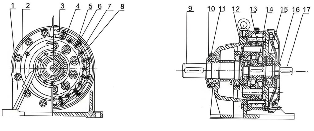
The operational principle of the 2K-V cycloidal drive involves a two-stage reduction process. The first stage is a conventional involute gear planetary train, where an input sun gear drives two or more planet gears. The second, and defining, stage is the cycloidal drive mechanism. The planet gears are mounted on eccentric crankshafts, which impart an oscillating motion to the cycloidal disks (cycloid gears). These disks mesh with a stationary ring of needle rollers (pinwheel). The eccentric motion of the cycloid disks, constrained by the rolling contact with the pins, results in a slow, reverse rotation of the disk itself. This rotation is extracted via the output carrier (planet carrier), achieving the significant speed reduction. This unique mechanism generates time-varying meshing forces and stiffness, which are the primary sources of dynamic excitation within the cycloidal drive.
1. Development of a High-Fidelity Dynamic Model
To accurately capture the dynamic behavior, a lumped-parameter model with 13 degrees of freedom (DOF) is developed. This model accounts for the most significant compliance and inertia elements in the power path. The DOFs include:
- Rotational DOFs: Input shaft, sun gear, two planet gears, two crankshaft sections, two cycloid disks, and the output carrier (9 DOFs).
- Translational DOFs: The centers of the two planet gears and the two cycloid disks are allowed to move in the plane of rotation, accounting for possible translational vibrations due to mesh forces (4 DOFs).
The model incorporates several stiffness components:
$$k_{spi} \text{ – Mesh stiffness between sun gear and planet gear } i$$
$$k_{ci} \text{ – Mesh stiffness between cycloid disk } i \text{ and the pinwheel}$$
$$k_I \text{ – Torsional stiffness of the input shaft}$$
$$k_{piHi} \text{ – Torsional stiffness of the crankshaft section near planet gear } i$$
$$k_{pi} \text{ – Bending stiffness of the crankshaft at the planet gear bearing location}$$
$$k_{ciHi} \text{ – Bending stiffness of the crankshaft at the cycloid disk bearing location}$$
Damping, while present, is often difficult to characterize precisely and is initially modeled as proportional damping for modal analysis. Applying Newton’s second law and kinematic constraints, the equations of motion are derived. For computational convenience in eigenvalue analysis, all angular displacements are transformed into equivalent linear displacements at a reference radius. The resulting matrix form of the free-vibration equation is:
$$ \mathbf{M} \ddot{\mathbf{x}} + \mathbf{C} \dot{\mathbf{x}} + \mathbf{K} \mathbf{x} = 0 $$
where $\mathbf{M}$ is the equivalent mass matrix, $\mathbf{C}$ is the damping matrix, $\mathbf{K}$ is the equivalent stiffness matrix, and $\mathbf{x}$ is the vector of equivalent linear displacements. The natural frequencies and mode shapes are obtained by solving the associated undamped eigenvalue problem:
$$ (\mathbf{K} – \omega_n^2 \mathbf{M}) \mathbf{\phi} = 0 $$
where $\omega_n$ are the natural frequencies and $\mathbf{\phi}$ are the corresponding mode shapes.
2. Parametric Influence on Dynamic Performance
The analysis focuses on a standard 2K-V-6 cycloidal drive with the following baseline parameters, against which variations are studied:
| Parameter | Symbol | Value |
|---|---|---|
| Sun Gear Teeth | $z_s$ | 10 |
| Planet Gear Teeth | $z_p$ | 34 |
| Module (Stage 1) | $m$ | 1 mm |
| Cycloid Disk Teeth | $z_c$ | 29 |
| Pinwheel Teeth | $z_b$ | 30 |
| Short Width Coefficient | $K_1$ | 0.675 |
| Eccentricity | $a$ | 0.9 mm |
| Pin Radius | $r_p$ | 2 mm |
| Pin Circle Radius | $R_p$ | 40 mm |
| Total Reduction Ratio | $i$ | 103 |
2.1 Impact of Tooth Profile Modification
In practice, a perfect conjugate cycloid profile is often modified to introduce a small amount of backlash, improve lubrication, and compensate for manufacturing errors and elastic deformations under load. This modification is typically defined by a profile shift coefficient $\lambda$. The analysis evaluates how $\lambda$ affects the crucial cycloidal drive meshing stiffness $k_c$.
As $\lambda$ increases, the initial clearance between the cycloid disk tooth and the pin increases. Under a constant transmitted torque, a larger clearance leads to greater overall deflection to take up the slack, reducing the number of tooth pairs in simultaneous contact. This increases the load per contact pair and the contact stress, thereby reducing the effective meshing stiffness. Furthermore, the cycloid disk is often a thin-walled structure, and increased stress exacerbates local deformation. The trend is clearly non-linear, as shown in the conceptual data below. A stiffer mesh generally leads to higher natural frequencies for the system.
| Modification Coefficient ($\lambda$) | Initial Clearance | Effective Contact Teeth | Relative Meshing Stiffness ($k_c/k_{c0}$) |
|---|---|---|---|
| 0 (Theoretical Conjugate) | Minimal | Maximum (~$z_b/2$) | 1.00 (Reference) |
| 2 | Small | Reduced | ~0.85 |
| 4 | Moderate | Further Reduced | ~0.70 |
| 6 | Large | Significantly Reduced | ~0.55 |
The design compromise is evident: some modification is necessary for practical operation, but excessive modification severely degrades stiffness and dynamic performance. The optimal $\lambda$ maximizes lubrication and assembly tolerance while minimizing the loss of effective mesh stiffness.
2.2 Influence of the Short Width Coefficient ($K_1$)
The short width coefficient $K_1 = a z_b / R_p$ is a fundamental parameter defining the trochoidal tooth profile. It significantly influences the curvature of the cycloid tooth. The analysis explores its impact in two regimes.
Regime 1: Larger $K_1$ Values (e.g., 0.68 to 0.90). Increasing $K_1$ increases the eccentricity $a$ for a fixed $R_p$ and $z_b$. The tooth profile becomes more pronounced, with a smaller convex radius of curvature $\rho_0$, given by:
$$ \rho_0 = \frac{R_p (1 + K_1^2 – 2K_1 \cos \phi)^{3/2}}{K_1(z_b + 1)\cos \phi – (1 + z_b K_1^2)} $$
where $\phi$ is the rotation angle of the crank arm. A smaller $\rho_0$ limits the maximum allowable pin radius to avoid interference. More critically, a larger $a$ results in a thinner wall section of the cycloid disk near the tooth root, reducing its structural rigidity. Consequently, the overall meshing stiffness decreases as $K_1$ increases. This effect is more pronounced for drives with fewer cycloid teeth ($z_c$), as the disk structure becomes even more delicate.
Regime 2: Smaller $K_1$ Values (e.g., 0.40 to 0.55). While a smaller $K_1$ leads to a thicker, more robust cycloid disk, it also reduces the pitch radii of both the cycloid disk ($r_c’ = K_1 R_p z_c / z_b$) and the pinwheel ($r_b’ = K_1 R_p$). For a constant output torque $T_{out}$, the tangential force at the mesh increases because the moment arm decreases:
$$ F_t \propto \frac{T_{out}}{r_c’} $$
Higher mesh forces lead to greater elastic deformation in the contact zone and the cycloid disk body, again resulting in a decrease in the effective meshing stiffness. Therefore, there exists an optimal range for $K_1$ that balances structural rigidity and force levels. Analysis suggests that for dynamic performance, a $K_1$ value in the range of 0.60 to 0.70 provides a favorable compromise, yielding higher mesh stiffness.
| $K_1$ Range | Eccentricity ($a$) | Disk Wall Thickness | Mesh Force (for fixed $T_{out}$) | Impact on Meshing Stiffness |
|---|---|---|---|---|
| Large (0.75-0.90) | Large | Thin, Low Rigidity | Lower | Strong Negative (Structural compliance dominates) |
| Medium (0.60-0.70) | Medium | Balanced | Medium | Optimal / Weaker Negative |
| Small (0.40-0.55) | Small | Thick, High Rigidity | Higher | Negative (High contact force dominates) |
2.3 Sensitivity Analysis of System Stiffnesses
The natural frequencies of the cycloidal drive, particularly the fundamental frequency (lowest natural frequency), are critical for avoiding resonance. The sensitivity of the fundamental frequency $f_{fund}$ to each stiffness component $k_i$ is analyzed by scaling them with a factor $c_{ki}$ (i.e., $k_i’ = c_{ki} k_i$) and observing the change in $f_{fund}$.
The results reveal a clear hierarchy of influence:
- Cycloid Meshing Stiffness ($k_{ci}$): This is the most sensitive parameter. Increasing $k_c$ by a factor of 2-3 leads to a dramatic increase (e.g., ~30%) in the fundamental frequency. Beyond this, the returns diminish, as other compliances in the system become the limiting factors.
- Crankshaft Bending Stiffness at Cycloid Disk ($k_{ciHi}$): This is the second most critical stiffness. Doubling this stiffness produces a noticeable increase in $f_{fund}$. However, further increases have a negligible effect once this stiffness is sufficiently high relative to the mesh stiffness.
- Other Stiffnesses: The torsional stiffness of the input shaft ($k_I$), the sun-planet mesh stiffness ($k_{spi}$), and the crankshaft bending at the planet gear ($k_{pi}$) show relatively minor influence on the fundamental frequency of the complete system. Their individual values are typically high enough that they do not become the weak link governing the lowest system mode.
This sensitivity analysis provides crucial guidance for design optimization: to raise the natural frequency and improve vibration characteristics, the primary focus must be on maximizing the cycloidal drive meshing stiffness and the crankshaft’s bending rigidity at the disk mounting location.
| Stiffness Component | Scaling Factor ($c_{ki}$) | Approx. Change in $f_{fund}$ | Design Implication |
|---|---|---|---|
| Cycloid Mesh Stiffness ($k_c$) | 1 → 2 | +20% to +25% | Highest priority for dynamic improvement. |
| 1 → 3 | +30% to +35% | ||
| 3 → 6 | +5% to +10% (Diminishing returns) | ||
| Crankshaft Bending Stiffness ($k_{ciHi}$) | 1 → 2 | +10% to +15% | Secondary priority. Important to ensure it is not the weak link. |
| 2 → 5 | Negligible change | ||
| Sun-Planet Mesh ($k_{spi}$), Input Shaft Torsion ($k_I$) | 1 → 6 | Very Small (< 5%) | Typically not governing for system base frequency. |
2.4 Role of the Pin Diameter Coefficient ($K_2$)
The pin diameter coefficient is defined as $K_2 = R_p / [r_p \cdot \sin(\pi / z_b)]$. It relates the pin circle radius, pin radius, and number of pins. For a fixed $R_p$ and reduction ratio, varying $K_2$ implicitly changes the number of cycloid teeth $z_c$ (since $i \propto z_b / (z_b – z_c)$). Increasing $K_2$ generally means using fewer, larger pins or reducing $z_b$, which leads to fewer cycloid teeth.
The analysis shows that as $K_2$ increases (and $z_c$ decreases), the fundamental natural frequency of the system tends to decrease. This is partly due to the changes in mass and inertia distribution. However, a crucial dynamic consideration is the primary excitation frequency. The major vibration excitation in a cycloidal drive often comes from the time-varying cycloidal drive mesh stiffness, with a fundamental frequency of:
$$ f_{exc} = \frac{n_2 \cdot (z_b – 1)}{60} $$
where $n_2$ is the output speed (in rpm) of the second stage. A larger $K_2$, associated with a smaller $z_b$, also lowers this excitation frequency $f_{exc}$. Therefore, while a larger $K_2$ might lower the system’s natural frequencies, it also lowers the dominant forcing frequency. The ratio between the excitation frequency and the natural frequency (which should be avoided) may not necessarily deteriorate. A value of $K_2$ around 2.0 is often found to provide a good balance, maintaining a sufficient number of teeth for load sharing while managing the frequency relationship. The choice must be evaluated in the context of the entire operating speed range to avoid resonances.
3. Conclusions and Design Guidelines
This detailed dynamic analysis of the 2K-V cycloidal drive elucidates the complex interplay between key design parameters and the system’s vibrational performance. The findings yield the following concrete conclusions and guidelines for engineers designing high-performance cycloidal drive systems:
- Tooth Profile Modification: While essential for manufacturability and lubrication, profile modification ($\lambda$) directly and significantly reduces the effective meshing stiffness of the cycloidal drive. The design must strike a precise balance, minimizing $\lambda$ to preserve stiffness while allowing necessary operational clearances.
- Short Width Coefficient ($K_1$): An optimal range exists for dynamic performance. Values of $K_1$ between 0.60 and 0.70 generally promote higher meshing stiffness. Values outside this range—either too high or too low—lead to reduced stiffness due to structural compliance or increased contact forces, respectively.
- System Stiffness Prioritization: The dynamic performance, characterized by the fundamental natural frequency, is overwhelmingly sensitive to two components: the cycloidal drive meshing stiffness ($k_c$) and the bending stiffness of the crankshaft at the cycloid disk mounting ($k_{ciHi$). Design efforts to increase system frequency should focus primarily on optimizing the cycloid tooth geometry, material, and heat treatment to maximize $k_c$, and on ensuring the crankshaft has ample diameter and robust bearing support to maximize $k_{ciHi}$.
- Pin Diameter Coefficient ($K_2$): Selecting $K_2$ involves a system-level consideration of frequency relationships. A value around 2.0 is commonly effective. The designer must verify that the resulting excitation frequencies $f_{exc}$ (a function of $z_b$ and output speed) do not coincide with the system’s natural frequencies across the entire operating envelope.
In summary, achieving a high-performance, low-vibration cycloidal drive requires a holistic design approach that carefully optimizes the cycloid tooth geometry (via $K_1$ and $\lambda$), strengthens the critical load path through the crankshaft, and selects tooth counts that favorably position excitation frequencies relative to system resonances. This analysis provides a foundational framework and quantitative insights for such an optimization process.