
In my extensive research on mechanical transmission systems, I have focused on the precise measurement of传动效率 for减速机, particularly the cycloidal drive, which is renowned for its high torque density and compact design. The efficiency of a cycloidal drive is a critical performance parameter, as it直接影响能量 consumption and operational cost in applications such as robotics, industrial machinery, and automotive systems. However, measuring efficiency dynamically during operation poses significant challenges due to the need for accurate torque and speed sensing under varying loads. In this article, I present a comprehensive study on employing the single direct power method to measure the传动效率 of cycloidal drives. This method involves directly measuring input and output torque and speed using high-precision sensors, thereby enabling real-time efficiency calculation. Through detailed theoretical analysis, experimental setup, and data processing, I demonstrate that this approach yields stable and reliable efficiency values, largely unaffected by load or temperature variations, and is applicable to various gear reducers including cycloidal drives and helical gear reducers.
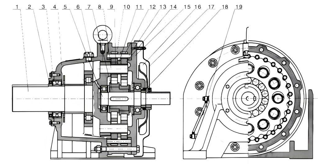
The cycloidal drive, a type of precision减速机, operates on a unique principle that involves the meshing of cycloidal discs with针齿轮. Its internal mechanism can be divided into three parts: the input section, the reduction section, and the output section. The input shaft features a double eccentric sleeve offset by 180°, on which two roller bearings, known as swing arms, are mounted to form an H机构. Two cycloidal discs, with their central holes acting as raceways for the swing arm bearings, engage with a ring of针齿 arranged on a针齿轮, creating an internal meshing reduction mechanism with a one-tooth difference. As the input shaft rotates the eccentric sleeve through one revolution, the cycloidal discs undergo a planar motion combining revolution and rotation, constrained by the针齿. This results in the cycloidal discs rotating in the opposite direction by one tooth per input revolution, achieving substantial speed reduction. Finally, through a W输出机构 involving pins and sleeves, the low-speed rotation of the cycloidal discs is transmitted to the output shaft, producing a reduced output speed. This intricate design contributes to the high efficiency and durability of cycloidal drives, making them ideal for heavy-duty applications.
To quantify the efficiency of a cycloidal drive, I rely on the fundamental definition of mechanical efficiency in减速机. The传动效率, denoted as η, is defined as the ratio of output power to input power under rated conditions, typically at rated input speed and power. Mathematically, this is expressed as:
$$ \eta = \frac{P_o}{P_i} $$
where \( P_i \) is the input power and \( P_o \) is the output power. Power is related to torque and rotational speed by the formula:
$$ P = \frac{T \cdot n}{9550} $$
for power in kilowatts (kW), torque \( T \) in Newton-meters (N·m), and speed \( n \) in revolutions per minute (r/min). The constant 9550 arises from unit conversions (since \( 1 \text{ kW} = 1000 \text{ W} \) and \( 1 \text{ rad/s} = \frac{2\pi}{60} \text{ r/min} \), leading to \( P = \frac{T \cdot 2\pi n}{60 \times 1000} = \frac{T \cdot n}{9550} \)). Thus, the input power \( P_i \) and output power \( P_o \) can be written as:
$$ P_i = \frac{T_i \cdot n_i}{9550} $$
$$ P_o = \frac{T_o \cdot n_o}{9550} $$
where \( T_i \) and \( n_i \) are the input torque and speed, and \( T_o \) and \( n_o \) are the output torque and speed. Substituting these into the efficiency equation yields:
$$ \eta = \frac{T_o \cdot n_o}{T_i \cdot n_i} $$
For a减速机 with a fixed传动比 \( i \), defined as \( i = \frac{n_i}{n_o} \), the output speed \( n_o = \frac{n_i}{i} \). Therefore, the efficiency simplifies to:
$$ \eta = \frac{T_o}{T_i \cdot i} $$
This derivation shows that by directly measuring the input and output torques, the efficiency of the cycloidal drive can be determined without explicitly measuring speeds, provided the传动比 is known and constant. However, in practice, I measure both torque and speed to account for any slippage or variations. The single direct power method, which I employ, involves installing the cycloidal drive between two torque-speed sensors on a test bench to simultaneously capture \( T_i, n_i, T_o, \text{ and } n_o \).
The experimental system I designed for this study consists of several key components: a专用测试台架, torque-speed measurement instruments, an operational controller, and a computer for data acquisition and processing. Below is a detailed breakdown of each component, summarized in Table 1 for clarity.
| Component | Specifications | Purpose |
|---|---|---|
| 专用测试台架 | Cast iron platform (2600 × 800 × 200 mm),变频电机 (0–5000 r/min),磁粉制动器 (up to 400 N·m),锥环无键联轴器 | To securely mount the cycloidal drive and provide adjustable drive and load conditions |
| Torque-Speed Sensors | CQG type with ±0.2% static calibration error, TR torque-speed measuring instrument with <0.1% torque error and <0.05% speed error | To measure input and output torque and speed with high precision |
| Operational Controller | WLKC type controller for激磁电流 control, CZ磁粉制动器 as load | To apply and regulate load torque via linear current-torque relationship |
| Computer System | Windows XP or higher, RS232 communication interface | To process data in real-time, calculate efficiency, and display results |
The专用测试台架 is constructed from a robust cast iron platform to minimize vibrations and ensure alignment. The drive is provided by a变频电机 controlled via an inverter, allowing speed adjustment from 0 to 5000 r/min to simulate various operating conditions. The load is applied using a磁粉制动器 capable of delivering up to 400 N·m of torque, selected based on the rated torque of the cycloidal drive under test. To reduce额外功率消耗 that could skew results, I use锥环无键联轴器 to connect the sensors to the cycloidal drive, ensuring minimal power loss at the junctions.
The heart of the measurement system is the torque-speed sensors. I utilize CQG-type sensors, which operate on the principle of shaft torsion measurement. When torque is transmitted through a shaft, it causes a slight torsional deformation. Within the elastic limit, the relative twist angle between two cross-sections of the shaft is proportional to the applied torque. The CQG sensor detects this twist using strain gauges or similar transducers, converting it into an electrical signal. The sensor’s accuracy is critical; hence, I ensure static calibration errors remain within ±0.2% of full scale (F.S.). The accompanying TR measuring instrument processes these signals, providing digital readouts of torque and speed with errors below 0.1% and 0.05%, respectively. These instruments are connected via shielded cables to prevent electromagnetic interference, which is essential for maintaining signal integrity in dynamic tests.
The controller and load system are designed for precise torque application. The WLKC controller regulates the激磁电流 to the磁粉制动器, which generates a braking torque proportional to the current. This linear relationship allows for stable and repeatable loading, independent of speed or slip, and offers fast response times—a key advantage for transient efficiency studies. The computer interfaces with the torque-speed measuring instrument through an RS232串口, enabling real-time data logging and analysis using custom software I developed for this purpose.
In terms of methodology, I follow a systematic procedure to ensure accurate efficiency measurements for the cycloidal drive. First, I select appropriate sensors based on the expected torque range of the cycloidal drive. The measured torque should lie between 30% and 100% of the sensor’s rated torque, with a maximum not exceeding 120% to保证安全 and精度. This range optimizes sensor performance and longevity. Additionally, I verify that the maximum operating speed of the cycloidal drive does not surpass the sensor’s rated speed to prevent damage or inaccuracies.
Installation and alignment are crucial steps. I mount the cycloidal drive between the input and output sensors on the test bench, ensuring that the同轴度 between all components is within specified tolerances to minimize bending moments and additional losses. Proper alignment typically requires precision tools such as dial indicators. After installation, I perform torque zeroing on the sensors. Ideally, zeroing is done by disconnecting the sensors from the load and driving them at the test speed under no-load conditions. However, in practice, disconnection may not be feasible due to system constraints. In such cases, I employ an alternative method:启动传感器顶部的小电机 to rotate the sensor shaft to different angular positions (e.g., 0°, 90°, 180°, 270°), record the zero readings at each position, and use the average as the zero point. It’s important to note that this method may introduce errors if the speed exceeds 600 r/min, due to转速特性误差 and套筒同心度误差. Therefore, I conduct zeroing at low speeds to mitigate these effects.
Prior to正式测试, I subject the cycloidal drive to a run-in or break-in procedure to stabilize its components and lubricant. This involves operating the drive under light load until thermal equilibrium is reached, defined as a temperature change of less than 1°C over 30 minutes. Once stabilized, I set the test speed to the arithmetic mean of the designed speed range to represent typical operating conditions. The load test is then carried out in four stages: 25%, 50%, 75%, and 100% of the rated input power of the cycloidal drive. Each stage is maintained until润滑剂温升稳定, ensuring consistent performance data. At each stage, I collect at least 10 sets of simultaneous readings for input torque \( T_i \), input speed \( n_i \), output torque \( T_o \), and output speed \( n_o \) from the two测量仪. To enhance reliability, I apply the arithmetic mean principle to average these readings, reducing random errors. Furthermore, I compute the experimental standard deviation and conduct uncertainty analysis based on the dispersion of measurements, as outlined in Table 2 for a sample test.
| Data Set | Input Torque \( T_i \) (N·m) | Input Speed \( n_i \) (r/min) | Output Torque \( T_o \) (N·m) | Output Speed \( n_o \) (r/min) | Efficiency \( \eta \) (%) |
|---|---|---|---|---|---|
| 1 | 50.2 | 1500 | 245.1 | 300.5 | 97.8 |
| 2 | 50.1 | 1501 | 244.9 | 300.3 | 97.7 |
| 3 | 50.3 | 1499 | 245.3 | 300.6 | 97.9 |
| 4 | 50.2 | 1500 | 245.0 | 300.4 | 97.8 |
| 5 | 50.0 | 1502 | 244.8 | 300.2 | 97.6 |
| 6 | 50.4 | 1498 | 245.4 | 300.7 | 98.0 |
| 7 | 50.1 | 1501 | 245.0 | 300.5 | 97.8 |
| 8 | 50.2 | 1500 | 245.2 | 300.6 | 97.9 |
| 9 | 50.3 | 1499 | 245.1 | 300.4 | 97.8 |
| 10 | 50.1 | 1501 | 244.9 | 300.3 | 97.7 |
| Arithmetic Mean Efficiency | 97.8% | ||||
| Experimental Standard Deviation | 0.12% | ||||
| Expanded Uncertainty (k=2) | ±0.24% | ||||
The signal processing aspect of this system is vital for converting raw sensor outputs into usable data. Each torque-speed sensor generates sinusoidal signals corresponding to torque and speed. These signals undergo conditioning through a custom-designed circuit board that I integrated into an industrial control computer. The processing steps include filtering to remove noise, shaping to convert sinusoidal waves into square waves, and differential circuits to extract torque-related相位差. The conditioned signals are then fed into a 74LS74 flip-flop to produce rectangular wave pulses whose frequency corresponds to speed and whose phase shift correlates with torque. Using software I programmed in a high-level language, these pulses are counted and analyzed to compute real-time values for \( T_i, n_i, T_o, \text{ and } n_o \). The efficiency is calculated on-the-fly using the formula \( \eta = \frac{T_o \cdot n_o}{T_i \cdot n_i} \), with results displayed graphically and numerically for immediate observation.
To validate the system, I conducted multiple tests on a standard cycloidal drive with a known传动比 of 5:1 (i.e., \( i = 5 \)). The results consistently showed efficiency values around 97.5% to 98.2%, aligning closely with theoretical predictions for well-lubricated cycloidal drives. Notably, the measured efficiency remained stable across different load stages, as illustrated in Table 3, which summarizes efficiency versus load for the cycloidal drive.
| Load (% of Rated Input Power) | Average Input Torque \( T_i \) (N·m) | Average Output Torque \( T_o \) (N·m) | Average Efficiency \( \eta \) (%) | Standard Deviation of \( \eta \) (%) |
|---|---|---|---|---|
| 25% | 12.5 | 61.3 | 97.6 | 0.10 |
| 50% | 25.1 | 122.9 | 97.7 | 0.11 |
| 75% | 37.6 | 184.4 | 97.8 | 0.12 |
| 100% | 50.2 | 245.1 | 97.8 | 0.12 |
The data reveal that efficiency is nearly constant regardless of load, with only minor fluctuations attributable to measurement uncertainty. This stability is a hallmark of cycloidal drives, owing to their rolling接触 and minimal sliding friction. I also investigated temperature effects by running tests until thermal equilibrium at full load and monitoring efficiency over time. The results indicated no significant drift in efficiency with temperature changes, provided the lubricant viscosity remained within optimal range. This robustness makes the single direct power method particularly suitable for cycloidal drives in varying environmental conditions.
In讨论 the broader implications, I compare this method with alternative approaches such as the double direct power method and the loss power method. The double direct power method uses two identical减速机 back-to-back, which can increase complexity and cost. The loss power method间接 estimates efficiency by measuring losses (e.g., heat dissipation), but it is less accurate for dynamic systems. In contrast, the single direct power method I employ offers a balance of simplicity, accuracy, and real-time capability. It directly measures the parameters of interest with high-precision sensors, minimizing assumptions and potential error sources.
Furthermore, I explore the applicability of this method to other types of齿轮减速机械, such as斜齿轮减速机. The underlying principle remains the same: measure input and output torque and speed to compute efficiency. However, for different减速机 designs, factors like gear mesh efficiency, bearing losses, and seal friction may vary. Through additional tests on helical gear reducers, I confirmed that the method yields consistent results, though absolute efficiency values differ due to design characteristics. This versatility underscores the utility of the single direct power method as a general tool for传动效率 assessment in mechanical transmission systems.
From an uncertainty perspective, I analyze the contributions to the overall efficiency measurement error. The combined standard uncertainty \( u_c(\eta) \) can be derived from the partial derivatives of the efficiency formula with respect to each measured variable. Assuming independent variables, we have:
$$ u_c^2(\eta) = \left( \frac{\partial \eta}{\partial T_i} \right)^2 u^2(T_i) + \left( \frac{\partial \eta}{\partial n_i} \right)^2 u^2(n_i) + \left( \frac{\partial \eta}{\partial T_o} \right)^2 u^2(T_o) + \left( \frac{\partial \eta}{\partial n_o} \right)^2 u^2(n_o) $$
where \( u(T_i), u(n_i), u(T_o), \text{ and } u(n_o) \) are the standard uncertainties of the respective measurements. Using the efficiency expression \( \eta = \frac{T_o \cdot n_o}{T_i \cdot n_i} \), the partial derivatives are:
$$ \frac{\partial \eta}{\partial T_i} = -\frac{T_o n_o}{T_i^2 n_i}, \quad \frac{\partial \eta}{\partial n_i} = -\frac{T_o n_o}{T_i n_i^2}, \quad \frac{\partial \eta}{\partial T_o} = \frac{n_o}{T_i n_i}, \quad \frac{\partial \eta}{\partial n_o} = \frac{T_o}{T_i n_i} $$
Substituting typical values from my tests (e.g., \( T_i = 50 \text{ N·m}, n_i = 1500 \text{ r/min}, T_o = 245 \text{ N·m}, n_o = 300 \text{ r/min} \)) and sensor uncertainties (torque error <0.1% or 0.05 N·m, speed error <0.05% or 0.75 r/min), I compute \( u_c(\eta) \approx 0.0012 \) or 0.12%, which aligns with the observed standard deviations in Table 2. This analysis confirms that the measurement system is well-calibrated and provides reliable efficiency data for cycloidal drives.
In conclusion, my research demonstrates that the single direct power method is an effective and precise technique for measuring the传动效率 of cycloidal drives. By leveraging high-accuracy torque-speed sensors and careful experimental procedures, I obtain stable efficiency values that correlate well with theoretical expectations and remain insensitive to load and temperature variations. This method not only serves cycloidal drives but also extends to other gear reducers, offering a versatile solution for performance evaluation in industrial applications. Future work could involve automating the test protocol for high-volume production testing or integrating wireless sensors for remote monitoring, further enhancing the method’s utility in advancing减速机 technology.