
A 30-day field validation at a coal mining area with an annual capacity of 15 million tonnes has demonstrated that an industrial embodied intelligence framework can move mine inspection beyond isolated robots, disconnected sensors, and delayed manual decisions. The tested system, built around a four-tier architecture and three technical lines, achieved a fault detection rate of 90.8%, an improvement of 35.8 percentage points over manual inspection, reduced single-scene inspection time by 68.9%, held virtual-real synchronization delay at 85 milliseconds or below, and maintained equipment availability above 99.2%. The results indicate that embodied intelligence can operate under harsh mining conditions and that the architecture is replicable for other mines seeking similar upgrades.
DOI: 10.12487/j.dt.2026.08.10
Keywords: Intelligent Mine Inspection; Industrial Embodied Intelligence; Digital Twin; Robot Collaboration; Integration of Sensing, Computing and Control
1. Policy Pressure and Operational Reality in Mine Inspection
Mining remains a core pillar of energy security, and its intelligent transformation has become a strategic requirement for high-quality development. In 2020, eight departments, including the National Development and Reform Commission and the National Energy Administration, issued the Guiding Opinions on Accelerating the Intelligent Development of Coal Mines, identified as Fagai Energy [2020] No. 283. The policy places reduction of personnel, efficiency improvement, cost reduction, and safety enhancement at the center of coal mine modernization. It calls for demonstration projects to move intelligent coal mine development from pilot exploration to deeper deployment, with a long-term goal that all types of coal mines basically achieve intelligent operations by 2035.
Despite this policy direction, traditional mine inspection continues to face multiple severe problems. Underground working environments are hostile. Dust concentration is high, vibration is strong, and gas explosion risks are present. Inspection personnel face safety threats every time they enter the mine. On a 3 km main roadway belt, for example, a manual inspection round trip takes more than 50 minutes. Limited by stamina and experience, missed detection rates can reach 30% to 50%. Faults in concealed locations, such as the underside of rollers and belt joints, are especially difficult to identify. In terms of labor cost, three-shift inspection requires continuous staffing. As labor costs rise year by year, the burden on enterprises grows heavier. More critically, fault response is often delayed by hours. By the time a problem becomes visible, an early hidden risk may already have evolved into a major fault.
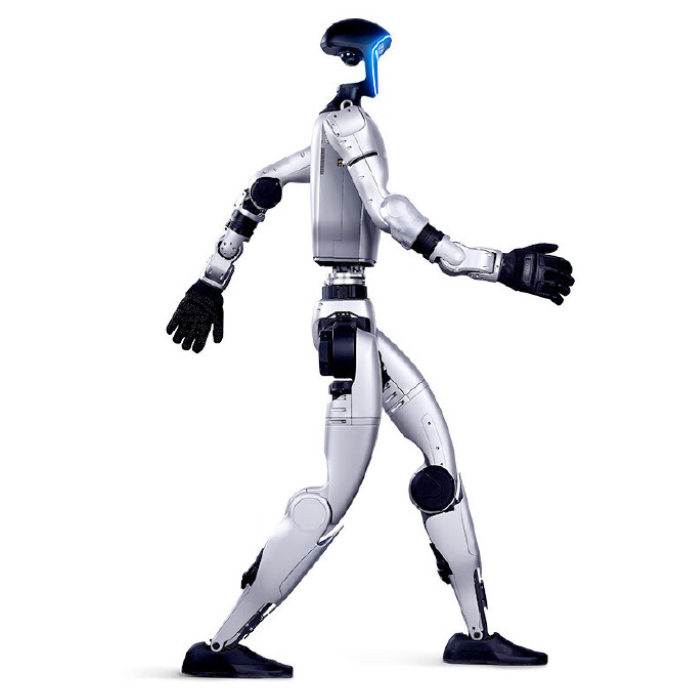
In recent years, embodied intelligence has attracted broad attention in academia and industry. Unlike traditional artificial intelligence, embodied intelligence places special emphasis on the body. An intelligent agent must rely on a physical entity to interact with the environment and complete tasks through cycles of perception, cognition, and action. This approach aligns closely with mine inspection requirements. The underground environment is complex, and inspection demands autonomous perception, autonomous decision-making, and autonomous execution. Cloud computing alone cannot satisfy these needs. If robots, sensors, and digital twin platforms are organically integrated into an embodied intelligent agent capable of interacting with the physical world, mine operations and maintenance models can undergo substantive change.
Three concepts are often mixed in existing literature: industrial embodied intelligence, intelligent systems, and intelligent agents. From a hierarchical perspective, industrial embodied intelligence emphasizes theory. Its core is the idea that an agent relies on a physical entity to interact with the environment and form a perception-cognition-action closed loop. An intelligent system is positioned at the engineering level. Any concrete system built under this concept belongs to this category, and the mine inspection system described here is one example. An intelligent agent refers to an entity unit within the system that can independently execute tasks, such as an inspection robot or a digital twin platform. These three are not parallel. They form a progressive relationship from concept to system to entity.
2. From Embodied Intelligence Theory to Industrial Mine Systems
Bringing embodied intelligence from the laboratory into industrial scenarios creates industrial embodied intelligence. Unlike traditional automation, which calculates without acting, the core feature of embodied intelligence is the body. An intelligent agent must rely on physical entities, including robots and sensors, to repeatedly verify actions in real environments and build perception, reasoning, and execution into a complete closed loop. Applied to mine inspection, this means the system cannot serve only as a data collector. It must possess perception capability through multimodal sensing, reasoning capability through digital twin simulation, and execution capability through robot operations, thereby achieving autonomous task completion on site.
In this framework, embodied intelligence is not a software layer added on top of existing equipment. It is an architectural principle that determines where sensing, computing, and control functions are placed, how data flows, and how physical and virtual systems interact. The mine inspection system described in this report applies embodied intelligence as a top-level design philosophy. The goal is to build a mine inspection agent with autonomous perception, autonomous decision-making, and autonomous execution. This requires that perception, computation, and control not be fully concentrated in the cloud. They must be pushed down to robots and edge gateways to ensure response speed and maintain basic operation when the network is interrupted. It also requires that the digital twin and the physical system not engage in one-way display. They must achieve bidirectional driving and real-time linkage. At the same time, the system must be open. It must adopt standard industrial protocols and modular design, support access from different manufacturers, and allow later function expansion without reconstructing the entire architecture.
3. Research Landscape and the Gaps That Persist
3.1 Robot Platforms for Mine Inspection
Current exploration of mine inspection technology is concentrated in several directions. In inspection robots, a domestically developed explosion-proof mine inspection robot has achieved Ex ib I Mb explosion protection and IP65 protection, allowing it to adapt to harsh underground environments. Related teams at China University of Mining and Technology have implemented autonomous navigation based on the ORB-SLAM2 algorithm. These developments show that mobile robot platforms can survive underground conditions and perform basic navigation tasks. However, a robot platform alone does not constitute an embodied intelligence system. It must be connected to fixed sensors, edge computing, cloud analysis, and digital twin decision-making to form a complete perception-cognition-action loop.
3.2 Digital Twin Models and Their Limits in Mining
In digital twin research, the five-dimensional model proposed by Tao Fei and colleagues provides a theoretical framework for industrial operations and maintenance. However, in the mining field, applications often remain at the stage of static display. The digital twin may visualize equipment and environment, but it does not form a dynamic closed loop with physical devices. This limits the ability of the twin to support real-time decision-making, task scheduling, and reverse control. For embodied intelligence to function in mine inspection, the digital twin must move from visualization to bidirectional interaction. It must not only receive physical state data but also send control commands and task adjustments back to robots and other field devices.
3.3 5G, Artificial Intelligence, and Communication-Centered Approaches
In the integration of 5G and artificial intelligence, related enterprises have promoted upgrades of mine communication networks. These efforts have improved data transmission capacity and network coverage. However, such solutions often focus on the data transmission capability itself. The complete closed loop of perception, decision-making, and execution has not been fully established. A high-speed network is necessary but not sufficient. Without seamless integration among robots, sensors, edge gateways, cloud platforms, and control systems, the network remains a pipe rather than a nervous system for embodied intelligence.
3.4 Data Silos, Delayed Decisions, and Weak Virtual-Physical Synchronization
Although progress has been made at the level of individual technologies, many problems still appear during actual underground operation. The most prominent is the obstacle to data fusion. Robots collect image data, sensors collect temperature and vibration data, and platforms use databases for storage. The data formats are not unified, forming mutually isolated data islands. Digital twin platforms may have achieved modeling, but they cannot reverse-control robots. Inspection tasks remain fixed in preset schedules and lack dynamic adjustment capability when sudden situations occur. In virtual-physical synchronization, some schemes have delays exceeding 200 milliseconds. The virtual model and the on-site state deviate from each other, making reliable decision-making difficult. Overall, existing solutions are mostly simple combinations of single-point devices. They do not yet possess organic collaboration capability. This is precisely the gap that an embodied intelligence approach is intended to close.
4. Design Goals and Overall Architecture of the Embodied Intelligence-Driven System
4.1 Design Objectives and Principles
The design phase takes industrial embodied intelligence as the top-level guiding concept. The objective is to build a mine inspection intelligent agent with autonomous perception, autonomous decision-making, and autonomous execution. The implementation must balance several directions. Perception, computation, and control functions cannot be entirely centralized in the cloud. They must be pushed down to robots and edge gateways to ensure response speed and maintain basic operation under network disconnection. The digital twin and the physical system cannot perform one-way display only. They must achieve bidirectional driving and real-time linkage. The system must also be open. It must adopt standard industrial protocols and modular design, support access from equipment of different manufacturers, and allow subsequent function expansion without reconstructing the overall architecture.
4.2 Four-Tier Architecture
The system adopts a layered design. From bottom to top, it includes the physical sensing layer, the edge transmission layer, the cloud fusion layer, and the decision control layer. The physical sensing layer consists of rail-mounted robots, wheeled robots, and fixed sensors such as wireless temperature and vibration sensors and deviation detectors. It completes multi-source data collection of underground environment and equipment status. The edge transmission layer uses intrinsically safe mining edge gateways to achieve time synchronization, protocol adaptation, and local preprocessing of multi-source data. The cloud fusion layer builds an improved CNN-LSTM fusion algorithm based on the TensorFlow framework and combines it with the Z-Engine three-dimensional visualization engine to achieve data fusion, fault diagnosis, and state mapping. The decision control layer uses a digital twin cockpit as its core. Based on analysis results, it issues scheduling commands to robots, forming a closed-loop control link of data uplink, analysis and decision, and command downlink.
| Layer | Main Components | Core Function | Key Output |
|---|---|---|---|
| Physical sensing layer | Rail-mounted robot, wheeled robot, wireless temperature and vibration sensors, deviation detectors | Multi-source collection of underground environment and equipment status | Images, infrared thermal data, temperature, vibration, deviation signals |
| Edge transmission layer | Intrinsically safe mining edge gateway | Time synchronization, protocol adaptation, local preprocessing | Time-aligned, protocol-normalized data streams |
| Cloud fusion layer | TensorFlow-based improved CNN-LSTM, Z-Engine visualization engine | Data fusion, fault diagnosis, state mapping | Fault diagnosis results, health status, virtual model updates |
| Decision control layer | Digital twin cockpit | Dynamic scheduling and command issuance | Robot dispatch commands, task preemption, closed-loop control |
4.3 Core Module Composition
Under the guidance of this architecture, the system is divided into four layers from bottom to top. In the physical sensing layer, one rail-mounted robot is deployed on the main roadway belt, one wheeled robot is deployed in the 35 kV substation, and fixed sensors such as wireless temperature and vibration sensors and deviation detectors are installed. Together they build a three-dimensional sensing network. In the edge transmission layer, intrinsically safe mining edge gateways complete time synchronization with NTP, with an error of plus or minus 5 milliseconds, protocol adaptation for MQTT, Modbus, and OPC-UA, and preprocessing. In the cloud fusion layer, an improved CNN-LSTM fusion algorithm is built on TensorFlow for fault diagnosis. A hot-warm-cold layered storage strategy using SSD, HDD, and MinIO manages data. In the decision control layer, a digital twin cockpit is built around the domestically developed Z-Engine. It integrates virtual-physical state mapping and dynamic task scheduling, that is, data uplink, analysis and decision, and command downlink, forming a complete closed-loop link.
5. Core Technology Implementation
The actual operation of the system depends on three core technologies: multimodal sensing collaboration, bidirectional linkage between the digital twin and robots, and edge-cloud collaborative decision-making. The following sections explain each in turn, with emphasis on algorithm principles and key parameters.
5.1 Multimodal Embodied Sensing Collaboration
Mine roadways are often several kilometers long, with many curves and severe occlusion. A single sensing method cannot achieve effective coverage. This system deeply integrates mobile robots and fixed sensors with the goal of full coverage and no blind spots. The main roadway belt is 3 km long and 2.7 m high. There are blind spots under rollers. The substation has dense equipment and many instruments. For these two scenarios, the system adopts a collaborative deployment scheme in which mobile robots are primary and fixed sensors are auxiliary.
For mobile robot configuration, the rail-mounted robot runs on an I-beam track above the belt. During commissioning, it was found that if a track joint has a height difference greater than 2 mm, the gimbal image will show obvious shaking. Mechanical damping pads were later installed to solve the problem. The gimbal has a vertical rotation range of plus or minus 90 degrees, monitoring height coverage from 1.2 m to 2.7 m, and horizontal coverage of the full belt width of 1.4 m. The robot automatically captures one high-definition image every 10 m and uses an infrared thermal imager to measure the temperature of each roller. The wheeled robot in the substation uses differential drive with positioning accuracy of plus or minus 30 mm. Its onboard VLP-16 lidar has a ranging range of 0.3 m to 100 m and accuracy of plus or minus 3 cm. With a SLAM algorithm, it can achieve autonomous navigation and dynamic obstacle avoidance. In actual testing, the substation has dense metal equipment, and the lidar experienced multipath reflection interference. Later, reflective plate markers were added and the scanning frequency was adjusted from 10 Hz to 20 Hz to improve positioning stability.
For fixed sensor configuration, the underside of rollers at a height of 0.65 m, belt joints, and motor bearing seats are blind areas for the robot. In these positions, one wireless temperature and vibration sensor is deployed every 30 m, and one deviation detector is installed every 50 m. In the substation, temperature sensors are attached to key parts such as transformer windings and switchgear contacts, with accuracy of plus or minus 0.5 degrees Celsius. This collaborative deployment forms a three-dimensional monitoring network with a horizontal interval of 50 m and full vertical coverage from 0.65 m to 2.7 m. The theoretical spatial coverage rate reaches more than 99%.
Because robots collect data while moving and fixed sensors collect data at fixed positions, their acquisition times and coordinate reference frames are inconsistent. Direct mixed calculation would produce large errors. The system designs a two-level processing pipeline to solve this problem: first time alignment, then spatial alignment.
For time alignment, all sensing devices, including robots, fixed sensors, and edge gateways, are synchronized with an NTP time server through the mining ring network. Synchronization accuracy is controlled within plus or minus 5 milliseconds. Specifically, the edge gateway initiates a time synchronization request to the NTP server every 30 seconds and uses the IEEE 1588 Precision Time Protocol to correct network transmission delay. Each data frame is assigned a globally unique timestamp when generated, in Unix timestamp format at millisecond level. For timestamp deviations caused by network jitter, the system uses a linear interpolation compensation algorithm. If a sensor collects values x0 and x1 at times t0 and t1, and the robot collection time is t, where t0 is less than t and t is less than t1, the compensated sensor data value is calculated by linear interpolation. This algorithm further reduces time synchronization error to within plus or minus 2 milliseconds.
For spatial alignment, the system uses the mine geographic information system map as the basis and constructs a unified coordinate system: eastward X, northward Y, and elevation Z. The origin is set at the head of the main roadway belt. During equipment deployment, all coordinates are calibrated using real-time kinematic positioning or total stations, with error controlled within 5 cm. During robot movement, the spatial position of collected data is determined jointly by odometry and lidar. Specifically, an extended Kalman filter fuses wheel encoder dead reckoning and lidar point cloud matching using the iterative closest point algorithm. It outputs robot pose at a positioning frequency of 50 Hz.
For the weighted fusion model, when the same monitoring target, such as the same roller temperature, may be measured simultaneously by a robot and a fixed sensor, the system uses the analytic hierarchy process to determine fusion weights. A judgment matrix is constructed using measurement accuracy, data freshness, and spatial matching degree as criteria. After expert scoring and consistency check with CR less than 0.1, the weight of robot infrared temperature measurement is set to 0.6, and the weight of fixed sensor temperature measurement is set to 0.4. The fused temperature value is calculated from these weights. The robot infrared temperature and fixed sensor temperature must first pass time alignment and spatial matching verification. A spatial distance of 1 m or less is considered the same target. Validation results show that the fused temperature measurement error is plus or minus 1.8 degrees Celsius, which is better than using the robot alone at plus or minus 2.5 degrees Celsius or the fixed sensor alone at plus or minus 2.0 degrees Celsius.
| Data Source | Weight in Fusion | Standalone Measurement Error | Fused Measurement Error |
|---|---|---|---|
| Robot infrared temperature measurement | 0.6 | Plus or minus 2.5 degrees Celsius | Plus or minus 1.8 degrees Celsius |
| Fixed sensor temperature measurement | 0.4 | Plus or minus 2.0 degrees Celsius | Plus or minus 1.8 degrees Celsius |
5.2 Event-Triggered Robot Coordination
In traditional inspection, fixed sensors and robots operate independently without linkage. This system designs a coordination mechanism of static sensing trigger and dynamic fine inspection review. Fixed sensors are deployed at key points and continuously collect data at 1 Hz. Once a value exceeds a limit, such as roller temperature above 75 degrees Celsius or vibration above 4.5 m per second squared, a high-priority alarm frame is immediately generated. It is published to the cloud through the edge gateway using MQTT QoS 2, with delay of 50 milliseconds or less. After receiving the alarm, the cloud parses the GIS coordinates of the alarm source and calls a path planning algorithm to calculate the optimal route for the robot to the target point. If the alarm point is not on the robot’s current inspection route, task preemption is directly triggered. After receiving the dispatch, the robot quickly arrives on site. The gimbal automatically aims at the target, adjusts to maximum optical zoom, and collects high-definition images and infrared thermal images. At the same time, the onboard gas sensor scans the surrounding environment. Finally, the robot’s fine inspection data and the continuous data from the fixed sensor are transmitted together to the cloud AI analysis module to output a diagnostic conclusion, classified into four levels: normal, attention, warning, and alarm.
Thus, the entire link from sensor anomaly discovery to robot arrival and review is connected. In field tests, 30 simulated overtemperature faults were created. The average time from sensor trigger to robot response was 2.8 seconds, more than 99% shorter than traditional manual response. This event-triggered coordination is a practical expression of embodied intelligence in mine inspection. The system does not merely observe; it senses an anomaly, reasons about the target, and acts through a physical robot.
5.3 Bidirectional Virtual-Physical Collaboration and Dynamic Scheduling
The digital twin model cannot serve only as a visualization tool. It must have the ability to reverse-control physical robots to achieve the core goal of controlling the real through the virtual. The virtual scene is built on the domestically developed Z-Engine. It fuses CAD design data with accuracy of 0.1 mm, BIM data, and oblique photography data with resolution of 0.05 m. It completes a 1:1 high-fidelity reproduction of the main roadway belt and the 35 kV substation at Tashan Coal Mine. The modeling workload is large. More than 300 devices, including belt conveyors, rollers, motors, transformers, and switchgear, are modeled one by one. The number of facets reaches 300,000, and the same-screen rendering frame rate remains above 35 fps. Moving parts such as belts, motor rotors, and robot gimbals are assigned physical properties including mass, friction coefficient, and moment of inertia to support subsequent multibody dynamics simulation. Each virtual model is bound to a data interface. The real-time state of physical equipment is passed in through parameter mapping.
To accurately reflect the operating state of physical equipment, the synchronization mechanism is critical. The system adopts a dual synchronization strategy of real-time push plus periodic verification. The mapping rules between physical parameters and virtual attributes are shown in the table below. For example, a physical belt speed of 4.5 m per second is linearly mapped to a virtual belt texture animation frame rate of 30 fps. Roller temperature uses a thermal color scale: 60 degrees Celsius or below is green, 60 to 80 degrees Celsius is yellow, and above 80 degrees Celsius is red.
| Physical Device Parameter | Measurement Accuracy | Virtual Model Attribute | Mapping Rule | Mapping Delay |
|---|---|---|---|---|
| Belt speed | Plus or minus 0.1 m per second | Virtual belt rotation frame rate | 4.5 m per second to 30 fps, linear proportional mapping | 80 milliseconds or less |
| Roller temperature | Plus or minus 1.8 degrees Celsius | Virtual roller thermal color scale | Below 60 degrees Celsius green; 60 to 80 degrees Celsius yellow; above 80 degrees Celsius red | 85 milliseconds or less |
| Motor speed | Plus or minus 5 r per minute | Virtual motor rotation speed | 1500 r per minute to 25 r per second, direct assignment | 75 milliseconds or less |
| Robot position | Plus or minus 30 mm | Virtual robot coordinate | Equal-scale mapping, 1:1 | 70 milliseconds or less |
In real-time push, the robot reports key parameters every 100 milliseconds, including position, speed, fault code, and current task ID. It reports ordinary parameters, such as each sensor measurement value, every 1 second. Fixed sensors push data once per second. In periodic verification, the digital twin platform performs a virtual-physical deviation check on each bound device every 5 seconds. It calculates the relative error between the virtual attribute value and the latest physical parameter. If the error exceeds 5%, remapping is triggered, forcing the virtual model to reacquire and update attribute values from the data bus. Under this mechanism, state mapping delay is 85 milliseconds or less. Position synchronization deviation is 30 mm or less for the rail-mounted robot and 28 mm or less for the wheeled robot. Temperature synchronization deviation is 1.6 degrees Celsius or less. This characteristic is especially important in weak-network underground environments.
Traditional inspection schedules are statically preset, and when a sudden situation occurs, the system can only wait for the next round. This system uses the real-time state awareness of the digital twin platform to replace the fixed timetable with a dynamic scheduling mechanism. Inspection tasks are divided by equipment importance and real-time operating state. Basic-layer temperature, humidity, and dust concentration collection has the lowest priority. Daily inspection of non-critical equipment such as auxiliary fans has the next lowest priority. Planned inspection of critical equipment such as the main belt and main transformer has medium priority. Further up, abnormal retesting after a fixed sensor alarm belongs to higher priority; such tasks must arrive on site for review as soon as possible. The highest priority is assigned to emergency faults: overtemperature alarms, severe deviation, personnel intrusion, and similar situations. Once they occur, all other tasks must be suspended.
For path planning, obstacles in the mine environment are divided into two categories: fixed equipment as static obstacles and temporary work vehicles and personnel as dynamic obstacles. The classic A* algorithm does not distinguish these two types of obstacles, so direct application has limitations. This system makes several improvements. It introduces an obstacle density term into the cost function so that the planned path actively avoids high-density areas and improves safety margin. It changes the search strategy to bidirectional search, expanding simultaneously from the start point and the end point, reducing the search space by about 40%. For dynamic obstacles, the digital twin platform tracks their position and speed in real time through cameras and lidar point clouds. Once a blocked path is detected, a new path can be recalculated within 500 milliseconds. The heuristic function is expressed as f(n) equals g(n) plus h(n) plus alpha times rho(n). Here f(n) is the estimated complete path cost from the start point to n and then to the target point. g(n) is the actual known cost from the start point to n. h(n) is the heuristic estimate from n to the target point, which is unknown and must be estimated. Alpha times rho(n) is the obstacle density weighting term, and alpha is a weighting coefficient set to 0.3.
For task preemption and switching, when a priority level 4 or above task appears, the system automatically triggers preemption. If the robot is executing a low-priority task, it immediately interrupts, saves the current position and completed steps, and turns to handle the high-priority task. The switching response time does not exceed 500 milliseconds. After the high-priority task is completed, the robot returns to the breakpoint and continues executing the original task. Field validation shows that this scheduling mechanism compresses robot task response time from the minute level in traditional mode to the second level. The average delay for emergency fault retesting is only 2.8 seconds.
5.4 Edge-Cloud Collaborative Intelligent Decision-Making
Fault identification must balance speed and accuracy. This system divides functions between the edge and the cloud. The edge is responsible for rapid response, and the cloud is responsible for deep analysis. The edge gateway undertakes about 80% of preprocessing work. Specifically, after time-series data such as vibration and temperature are connected, median filtering with a window size of 5 is first performed to remove impulse noise. Data from different protocols, such as Modbus, CAN, and custom serial ports, is uniformly converted to JSON format with timestamps and device IDs. Then, screening is performed according to the 3-sigma principle. Isolated data points that clearly exceed the normal range are directly removed to prevent erroneous data from being uploaded.
The cloud AI analysis module is built on the TensorFlow framework. Specialized deep learning models are trained for different fault types. For belt deviation visual recognition, underground dust concentration is high, image contrast is low, and the deviation features are subtle. Standard YOLOv5 does not perform well under these conditions. This system optimizes the backbone network CSPDarknet53 by replacing some 3 by 3 convolutions with asymmetric convolutions of 1 by 3 and 3 by 1. This keeps the receptive field unchanged while reducing the number of parameters by 35% and accelerating inference speed by 20%. In addition, a contrast-limited adaptive histogram equalization module is added before the input layer to process dusty images, enhance local contrast, and improve belt edge clarity. The model is trained on 10,000 annotated images, with a training, validation, and test split of 7:2:1. Test results show that mAP at 0.5 is 91.7%, and inference time is 50 milliseconds per frame or less on an NVIDIA Jetson AGX Xavier.
For equipment abnormal sound diagnosis, this study conducts in-depth work on acoustic diagnosis. It collects 12,000 samples covering six fault types, including roller abnormal sound, motor bearing wear, and gear meshing abnormality. It uses 40-dimensional Mel-frequency cepstral coefficients to extract features from fault acoustic signals and feeds them into a two-layer LSTM network with 128 hidden units and a time step of 10. The model outputs a probability distribution for each fault type, with overall accuracy reaching 88.2%. For judgments with confidence below 0.7, the system does not issue a forced conclusion. Instead, it marks them as pending manual review and pushes the audio segment to the digital twin platform for maintenance personnel review.
5.5 Equipment Health Assessment and Trend Prediction
The health assessment model uses a weighted scoring method to construct an equipment health index from 0 to 100. It comprehensively considers three indicators: temperature, vibration, and operating duration. The weights are 0.4 for temperature, 0.3 for vibration, and 0.3 for duration, determined by the entropy weight method. Temperature is evaluated against the normal operating range, with minimum and maximum values. Vibration is evaluated against the alarm threshold. Duration is evaluated against the design life. A health index below 60 is classified as needs maintenance. A health index below 40 is classified as urgent repair. The model is validated on historical fault data containing 1.2 million records, with accuracy of about 85%.
Trend prediction uses an LSTM time-series model. It inputs the operating data of the equipment over the past 7 days, with a time step of 24, meaning 24 sampling points per day, and outputs predicted values for the next 7 days. The network structure is an input layer of 24 dimensions, an LSTM layer of 64 units, a dropout layer with a rate of 0.2, and a fully connected layer with 7-dimensional output. Training uses the Adam optimizer, and the loss function is mean squared error. Prediction error is controlled within plus or minus 5%. This indicator is calculated by comparing predicted temperature with measured temperature. More practically, the trend prediction function is valuable. When the model predicts that the health index of a device will fall below 60 within 72 hours, the system automatically increases inspection frequency from once every 2 hours to once every half hour. As a result, a warning can be generated more than 24 hours before a fault occurs, providing maintenance personnel with sufficient intervention time.
6. Field Validation and Result Analysis
6.1 Validation Scenario and Scheme Design
The validation site is a coal mine of China Coal with an annual capacity of 15 million tonnes. The validation objects are the main roadway belt, with a total length of 3 km, and a 35 kV substation with a building area of 800 square meters. The validation period is 30 days, in June 2025. The field deployment includes one rail-mounted robot, one wheeled robot, six wireless temperature and vibration sensors, three deviation detectors, ten temperature sensors, and other equipment. The validation indicators involve three dimensions: collaboration efficiency, including single-scene inspection time and fault response time; collaboration accuracy, including virtual-real synchronization deviation and fault detection rate; and environmental adaptability, including equipment availability and data packet loss rate.
6.2 Collaboration Efficiency
In terms of collaboration efficiency, the single-scene inspection time for the main roadway belt scenario was compressed from 45.0 plus or minus 2.3 minutes by manual inspection to 14.4 plus or minus 1.5 minutes, a reduction of 68.9%. Fault response time fell from 1500 plus or minus 186 seconds to 126 plus or minus 18 seconds, a reduction of 91.6%. The substation scenario also improved significantly. Inspection time was reduced from 30.0 plus or minus 1.8 minutes to 9.3 plus or minus 1.1 minutes, a reduction of 68.9%. Fault response time was reduced by 92.0%. Manual intervention counts in both scenarios fell to below 0.5 times per day.
| Scenario | Manual Inspection Time | System Inspection Time | Time Reduction | Manual Response Time | System Response Time | Response Reduction |
|---|---|---|---|---|---|---|
| Main roadway belt | 45.0 plus or minus 2.3 minutes | 14.4 plus or minus 1.5 minutes | 68.9% | 1500 plus or minus 186 seconds | 126 plus or minus 18 seconds | 91.6% |
| 35 kV substation | 30.0 plus or minus 1.8 minutes | 9.3 plus or minus 1.1 minutes | 68.9% | Not separately reported | Not separately reported | 92.0% |
6.3 Collaboration Accuracy and Fault Detection
In terms of collaboration accuracy, virtual-real synchronization testing showed that the average position deviation of the rail-mounted robot was 8 plus or minus 2 mm, the wheeled robot was 28 plus or minus 3 mm, and the temperature synchronization deviation was 1.6 plus or minus 0.2 degrees Celsius. For fault detection, among 120 simulated fault samples, the overall system detection rate was 90.8%, which is 35.8 percentage points higher than the manual inspection rate of 55.0%. Among fault types, instrument reading abnormality had the highest detection rate at 96.7%. Equipment abnormal sound detection was relatively lower at 83.3%, mainly due to interference from environmental background noise. The overall false positive rate was 5.0%.
| Fault Detection Metric | Result |
|---|---|
| Overall system fault detection rate | 90.8% |
| Manual inspection fault detection rate | 55.0% |
| Improvement over manual inspection | 35.8 percentage points |
| Instrument reading abnormality detection rate | 96.7% |
| Equipment abnormal sound detection rate | 83.3% |
| Overall false positive rate | 5.0% |
6.4 Environmental Adaptability
In terms of environmental adaptability, the system ran continuously for 72 hours under extreme conditions with dust concentration of 800 mg per cubic meter, humidity of 90%, and temperature of minus 15 degrees Celsius. Equipment availability was 99.2%. Data packet loss rate was 0.3% after deployment of signal relays. Robot action accuracy was 98.5%. These results show that the embodied intelligence architecture can maintain stable operation in harsh underground conditions, rather than functioning only in controlled laboratory environments.
6.5 Comparative Performance Against Mainstream Approaches
The system is compared horizontally with three mainstream approaches in the industry. Mainstream approach A adopts an explosion-proof inspection robot route. Single-machine capability is strong, but robots, sensors, and platforms operate independently without linkage. This system uses a different scheme, deeply integrating robots, sensors, and the twin platform to achieve real-time data exchange and unified task scheduling. Mainstream approach B has autonomous navigation capability but does not integrate prediction functions. This system carries an LSTM prediction model and can provide early warning of 24 hours or more. Mainstream approach C, in the 5G plus mine communication direction, focuses on building a high-speed communication foundation but does not form a decision-execution closed loop. This system achieves full-link connectivity from perception to decision to execution, with response time of 3 seconds or less.
From the data comparison, in fault detection rate, most industry solutions are 55% to 70%, while this system reaches 90.8%. In virtual-real synchronization delay, industry solutions usually exceed 200 milliseconds, while this system controls it within 85 milliseconds. In inspection efficiency, industry solutions claim improvements of 30% to 50%, while this system achieves a measured improvement of 68.9%. The three indicators show substantive gaps and are not at the same level.
| Comparison Dimension | Mainstream Approach A | Mainstream Approach B | Mainstream Approach C | Embodied Intelligence System |
|---|---|---|---|---|
| Robot capability | Strong single-machine capability | Autonomous navigation | Communication-centered | Robot, sensor, and twin integration |
| Fault detection rate | Typically 55% to 70% in the industry | Typically 55% to 70% in the industry | Typically 55% to 70% in the industry | 90.8% |
| Virtual-real synchronization delay | Usually above 200 milliseconds | Usually above 200 milliseconds | Usually above 200 milliseconds | 85 milliseconds or less |
| Inspection efficiency improvement | Claimed 30% to 50% | Claimed 30% to 50% | Claimed 30% to 50% | 68.9% measured |
| Closed-loop decision and execution | Not fully linked | No prediction integrated | No complete decision-execution loop | Perception to decision to execution fully connected |
6.6 Analysis of Anomalous Results
During validation, the equipment abnormal sound detection rate of 83.3% was lower than other indicators. The reason is that mine background noise, such as belt operation sound and ventilation fan sound, has a complex spectrum. Some early weak abnormal sound features are submerged by noise. Follow-up plans include introducing signal denoising algorithms such as wavelet packet transform and adding microphone arrays to improve the signal-to-noise ratio. This is a specific engineering challenge, not a failure of the embodied intelligence architecture itself. It shows that embodied intelligence in mining must continue to improve multimodal sensing, especially acoustic sensing under extreme industrial noise.
7. Operational and Economic Implications
The field results have direct operational and economic implications. For coal mines, the system can save approximately 2.05 million yuan in costs each year. The number of manual underground trips is reduced by about 70%. This reduction matters not only for cost but also for safety. Fewer underground trips mean fewer personnel exposed to dust, vibration, gas risk, and heavy machinery. At the same time, faster fault response and higher detection rates reduce the probability that an early hidden risk evolves into a major fault. The embodied intelligence system does not replace human judgment entirely. It shifts human work from repetitive dangerous inspection to higher-level review, maintenance planning, and exception handling.
The architecture also has replicability. It is designed with standard industrial protocols and modular components, allowing different manufacturers to connect equipment and allowing later expansion without reconstructing the entire system. The four-tier architecture separates physical sensing, edge transmission, cloud fusion, and decision control. This separation makes the system adaptable to different mines, different equipment layouts, and different communication conditions. The field validation at a 15 million tonne annual capacity mine suggests that the approach can be extended to similar mining operations.
8. Limitations and Future Work
Several directions deserve deeper work. In multi-robot swarm collaboration, the plan is to develop swarm scheduling algorithms based on the digital twin platform and to combine them with a 5G private network with latency of 20 milliseconds or less to achieve joint operations of rail-mounted and wheeled robots. In algorithm deployment, the plan is to deploy core diagnostic models to the edge and introduce mine-specific vertical large models to enhance the system’s ability to recognize rare faults. The application scope of the digital twin is also expected to expand from the current inspection link to the full lifecycle management of equipment maintenance and even retirement decisions, enabling predictive maintenance.
These future steps all depend on the same principle: embodied intelligence must remain grounded in physical interaction. The more the system senses, reasons, and acts in the real mine environment, the more valuable it becomes. The current system already demonstrates that embodied intelligence can connect robots, sensors, edge gateways, cloud analytics, and digital twins into a coherent inspection agent. The next stage is to deepen that coherence across more robots, more equipment, and more stages of the asset lifecycle.
9. Conclusion
Mine inspection has troubled the industry for years. Robots, sensors, and platforms operate independently. Data cannot be exchanged. Decision response lags. This study does not remain at the conceptual level. Based on industrial embodied intelligence theory, it builds a deployable engineering system. Multimodal sensing collaboration, bidirectional virtual-physical closed-loop control, and edge-cloud collaboration address three core problems: blind spot coverage, data exchange, and rapid response. The 30-day field validation at a coal mine shows a fault detection rate of 90.8%, an improvement of 35.8 percentage points over manual inspection. Inspection efficiency improves by nearly 70%. Virtual-real synchronization delay is controlled within 85 milliseconds. For coal mines, the system can save approximately 2.05 million yuan per year and reduce manual underground trips by about 70%. The architecture can be promoted to other similar mines and has good replicability.
The broader significance is that embodied intelligence is not only a laboratory concept. In the harsh conditions of a mine, embodied intelligence can support autonomous perception, autonomous decision-making, and autonomous execution when it is embedded in a four-tier architecture, connected by multimodal sensing, digital twin interaction, and edge-cloud analysis. The results provide engineering evidence that industrial embodied intelligence can move from theory to practice in one of the most demanding industrial environments. As multi-robot collaboration, edge deployment, mine-specific large models, and full-lifecycle digital twins mature, the role of embodied intelligence in mine inspection and maintenance is expected to expand further.