
The continuous advancement of smart manufacturing has firmly established industrial robots as the core equipment on modern production lines. As the critical component that directly executes tasks, the stability and precision of the end effector directly influence the production efficiency and product quality of the entire robotic system. During long-term operation, end effectors are frequently subjected to complex loads and variable working conditions, leading to issues such as structural fatigue, sensor failure, and performance degradation, which compromise stable operation. Therefore, from a mechanical design perspective, enhancing the structural strength of the end effector, from a systems control perspective, ensuring its coordination with the robot body, and from a motion control perspective, achieving rapid fault diagnosis and resolution, have become pressing technical challenges in today’s smart manufacturing landscape. This article delves into these aspects, providing a detailed analysis of diagnostic methodologies and maintenance strategies.
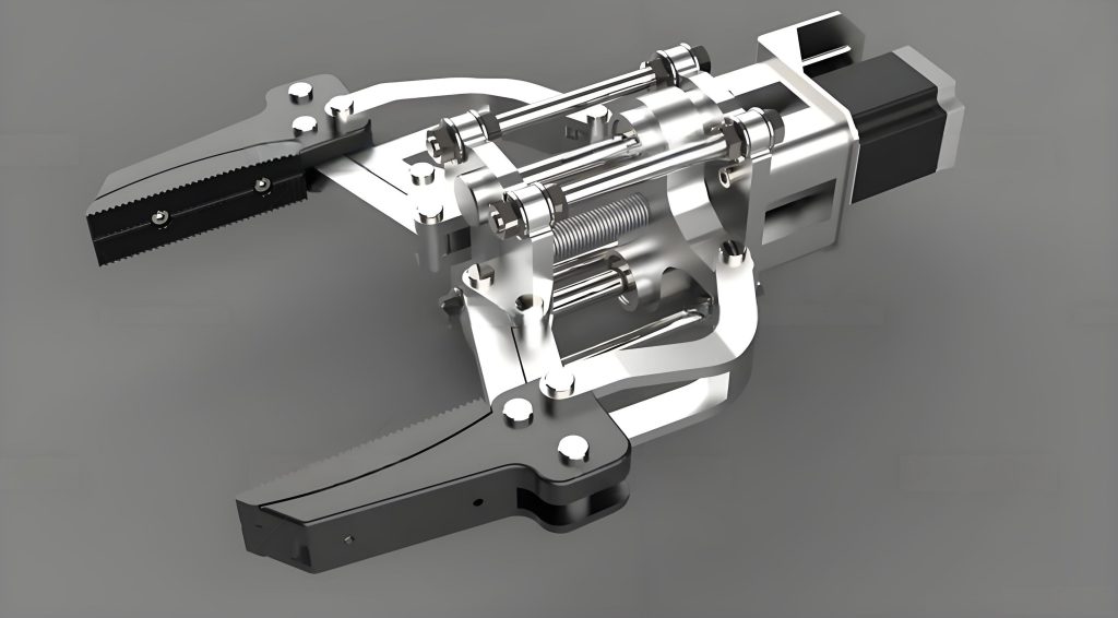
An Overview of the Industrial Robot End Effector
Fundamental Structure and Classification
The primary function of an industrial robot end effector is to execute various process operation commands. Its basic structure typically comprises a main frame, drive unit, sensor module, and interface components. The main frame determines the load-bearing capacity and rigidity of the end effector. The drive unit is responsible for action execution. The sensor module collects operational state data, and the interface components ensure a stable connection between the robot body and the process system. Based on functional differences, end effectors can be categorized into three main types, as summarized in the table below.
| End Effector Type | Primary Function | Typical Examples |
|---|---|---|
| Universal | Grasping, holding, or handling standard objects. | Mechanical grippers/jaws, vacuum suction cups. |
| Specialized | Performing a specific industrial process. | Welding torches, spray painting guns, drilling heads. |
| Compound/Intelligent | Integrated sensing and adaptive control for complex tasks. | Force-controlled smart grippers, vision-integrated tool changers. |
During the design phase, engineers must strike a balance between lightweight design and structural strength. An excessively heavy end effector increases the inertial load on the robot’s joints, potentially degrading its overall performance, accuracy, and dynamic response.
Key Points in Mechanical Design and Motion Control
The holistic design of an end effector must not only adhere to principles of rationality but also integrate closely with the robot’s motion control system. In mechanical design, the focus is on ensuring a compact structure and balanced mass distribution to minimize inertia and energy consumption. In motion control, the goal is to achieve efficient coordination between the end effector and the robot’s joint servo systems for precise control over position, velocity, and applied force.
This synergy is critical. For instance, in an assembly task, a gripper must not only close on a part but also, in conjunction with a force control algorithm, apply a precise clamping force $F_{clamp}$ to prevent damage, often governed by a control law like:
$$ \tau_{motor} = J^T(\theta) \cdot (K_p \cdot e_x + K_d \cdot \dot{e}_x) + f(F_{desired}, F_{measured}) $$
where $J(\theta)$ is the Jacobian matrix, $e_x$ is the position error, and $f$ is the force compensation function. In welding, the torch must follow a precise trajectory $T(t)$ synchronized with the robot’s motion to ensure uniform weld quality. Thus, robust mechanical design reduces the compensation burden on the motion controller, while advanced control mitigates uncertainties from mechanics or the environment.
Performance Requirements Under Different Working Conditions
Industrial robot end effectors often operate in harsh and complex environments, making their performance and lifespan susceptible to various external factors. The requirements vary significantly across industries, which necessitates tailored design approaches.
| Industry | Primary Hazards/Requirements | End Effector Design Implications |
|---|---|---|
| Automotive Manufacturing | High temperature, arc spatter, mechanical impact. | Use of heat-resistant materials (e.g., aluminized steel), protective shrouds. |
| Food & Pharmaceutical | Strict hygiene, moisture, corrosive cleaning agents. | Stainless steel construction, sealed designs, easy-clean surfaces. |
| Electronics Assembly | Precision, electrostatic discharge (ESD) sensitivity. | High-tolerance mechanisms, ESD-safe materials (e.g., carbon-filled polymers). |
| General Industry | Abrasive dust, oil mist, vibrations, chemical exposure. | Enhanced sealing (IP ratings), wear-resistant coatings, vibration damping. |
Environmental factors like dust, vibration, and chemicals accelerate wear and aging, inducing fatigue and shortening the service life of the end effector. Therefore, engineers must incorporate optimization measures such as protective housings, high-wear-resistant materials, and redundant sensors to ensure stable operation in complex settings.
Typical Fault Diagnosis Methods for the Industrial Robot End Effector
Diagnosis Based on Signal Features
Methods based on signal feature analysis are intuitive and efficient, widely applied for fault diagnosis in end effectors. These techniques involve acquiring signals such as vibration, temperature, acoustic emission, and motor current during operation. Features are then extracted using time-domain, frequency-domain, or time-frequency domain analysis to identify abnormal states.
A classic approach is to monitor the root mean square (RMS) value of vibration acceleration, a common time-domain indicator:
$$ a_{RMS} = \sqrt{\frac{1}{N} \sum_{i=1}^{N} a_i^2} $$
A significant increase in $a_{RMS}$ often indicates growing imbalance or looseness. In the frequency domain, the appearance or amplification of specific frequency components can pinpoint faults. For example, bearing defects often manifest at characteristic frequencies calculated from bearing geometry and rotational speed $f_r$:
$$ f_{BPFO} = \frac{N_b}{2} f_r \left(1 – \frac{B_d}{P_d} \cos\phi\right) $$
$$ f_{BPFI} = \frac{N_b}{2} f_r \left(1 + \frac{B_d}{P_d} \cos\phi\right) $$
where $f_{BPFO}$ is the Ball Pass Frequency Outer race, $f_{BPFI}$ is the Ball Pass Frequency Inner race, $N_b$ is the number of balls, $B_d$ is the ball diameter, $P_d$ is the pitch diameter, and $\phi$ is the contact angle.
A practical implementation framework is summarized below:
| Signal Type | Potential Fault Indicator | Typical Analysis Method |
|---|---|---|
| Vibration | Unbalance, misalignment, bearing wear, gear damage. | FFT Spectrum, Envelope Analysis, Wavelet Transform. |
| Temperature | Bearing seizure, motor overload, excessive friction. | Trend monitoring, Threshold alarms. |
| Motor Current | Electrical faults, mechanical binding, load anomalies. | Current Park’s Vector Analysis, Harmonic analysis. |
| Acoustic Emission | Crack initiation/propagation, subtle friction changes. | Event counting, Energy level monitoring. |
The diagnosis typically involves establishing a baseline signal profile under normal conditions and comparing real-time signals against it. While simple and fast, these methods are susceptible to noise in complex environments, often necessitating integration with advanced filtering and signal processing techniques.
Diagnosis Based on Kinematic and Dynamic Models
This model-based approach leverages the theoretical understanding of the robot and end effector system. Kinematic and dynamic models predict expected values for parameters like position, velocity, acceleration, and joint torque. Discrepancies between predicted values $\hat{x}$ and actual measured values $x_m$ can reveal faults such as structural deformation, connection loosening, or control performance degradation.
Kinematic Analysis: Focuses on geometry and motion without considering forces. The forward kinematics model defines the end effector pose $X$ based on joint angles $\theta$:
$$ X = f_{kin}(\theta) $$
Trajectory tracking errors, calculated as $e = X_{desired} – X_{actual}$, can indicate issues like gear backlash, encoder miscalibration, or deflection in the end effector structure under load.
Dynamic Analysis: Considers forces and torques. A simplified dynamic model for a robot joint (including the end effector load) can be expressed as:
$$ \tau = M(\theta)\ddot{\theta} + C(\theta, \dot{\theta})\dot{\theta} + G(\theta) + \tau_{friction} + \tau_{disturbance} $$
Where $\tau$ is the joint torque, $M$ is the inertia matrix, $C$ represents Coriolis and centrifugal forces, and $G$ is the gravity vector. By comparing the expected torque $\tau_{model}$ from this equation with the actual torque $\tau_{measured}$ from the servo drive, one can detect anomalies. A persistent offset or unusual pattern in the residual $\tau_{residual} = \tau_{measured} – \tau_{model}$ might signal increased friction, additional loading from a damaged end effector component, or a change in the end effector‘s inertial properties.
This method provides deep insight into the coupled relationship between the end effector and the robot’s control system. However, its accuracy is highly dependent on the fidelity of the model parameters (e.g., mass, center of gravity, inertia of the end effector). Inaccurate parameters or significant environmental changes can lead to false diagnostics.
Diagnosis Based on Artificial Intelligence Algorithms
The advent of AI and big data has propelled the use of intelligent algorithms for end effector fault diagnosis. Machine learning (ML) and deep learning (DL) models can automatically learn complex patterns and correlations from historical and real-time operational data, often achieving superior accuracy and adaptability compared to traditional methods.
These approaches typically follow a pipeline: data acquisition from multiple sensors on the end effector and robot, feature extraction (sometimes automated in DL), model training, and inference. A common ML model is the Support Vector Machine (SVM), which finds an optimal hyperplane to separate different fault classes based on input features. For sequential time-series data, Recurrent Neural Networks (RNNs) or Long Short-Term Memory (LSTM) networks are powerful. A simple representation of a neuron’s operation in such a network is:
$$ y = \sigma\left(\sum_{i=1}^{n} w_i x_i + b\right) $$
where $x_i$ are inputs (e.g., sensor readings), $w_i$ are weights, $b$ is the bias, and $\sigma$ is an activation function.
Training often involves minimizing a loss function, such as cross-entropy for classification:
$$ L = -\frac{1}{N} \sum_{i=1}^{N} \sum_{c=1}^{C} y_{i,c} \log(\hat{y}_{i,c}) $$
where $y_{i,c}$ is the true label and $\hat{y}_{i,c}$ is the predicted probability for class $c$ of sample $i$.
The comparative advantages and challenges of this paradigm are outlined below:
| Aspect | Advantage | Challenge |
|---|---|---|
| Accuracy & Adaptability | Excels at handling complex, non-linear patterns and multi-source data fusion. | Requires large volumes of high-quality, labeled training data. |
| Feature Engineering | Deep learning can automate feature extraction from raw data. | Traditional ML still requires domain expertise for feature selection. |
| Prognostic Ability | Can enable predictive maintenance by estimating Remaining Useful Life (RUL). | Model interpretability can be low (“black-box” issue). |
| Computational Demand | Effective for complex diagnostics. | Training and inference require significant computational resources. |
These AI-driven methods provide strong support for developing predictive maintenance strategies for the end effector.
Analysis of Common End Effector Faults
Faults in the end effector system can be broadly categorized, highlighting the critical areas for monitoring and maintenance.
| Fault Category | Subsystem | Common Manifestations & Causes |
|---|---|---|
| Execution & Sensing System Faults | Drive/Actuation | Motor overheating/overload, servo amplifier failure, gear/belt wear, lead screw backlash, pneumatic cylinder leakage. |
| Sensing | Force/torque sensor drift or saturation, proximity sensor contamination, encoder signal loss, temperature sensor failure. | |
| Motion Control System Faults | Control Algorithm | Trajectory following errors, oscillatory response, force control instability due to improper PID gains ($K_p, K_i, K_d$). |
| Servo Performance | Increased tracking error, torque ripple, bandwidth reduction due to aging components or electrical noise. | |
| Structural & Mechanical Faults | Mechanical Frame | Crack propagation, permanent deformation, joint play, fastener loosening, seal failure leading to contamination ingress. |
For example, wear in a gripper’s linkage increases backlash, modeled as a dead zone in the position transfer function, causing poor repeatability. Drift in a force sensor’s zero point $F_{zero}$ leads to incorrect clamping force calculation: $F_{applied} = k \cdot (V_{read} – V_{zero}) + \Delta F_{drift}$. Motion control faults are often linked to system design, parameter tuning, and component aging, necessitating early identification via model analysis and online monitoring.
Maintenance Strategies for the Industrial Robot End Effector
Reactive Repair and Preventive Maintenance Strategy
Reactive repair, or corrective maintenance, involves actions taken after an end effector fault occurs, such as replacing damaged parts or repairing worn components. While it restores function, it leads to unplanned downtime and higher long-term costs. Preventive maintenance (PM) aims to reduce this risk by performing scheduled activities regardless of the end effector‘s current condition. A combined strategy is essential.
A typical PM checklist for an end effector includes:
- Lubrication: Re-greasing gears and linear guides at interval $T_{lube}$.
- Calibration: Verifying and calibrating force/torque sensors and vision systems.
- Inspection: Checking for mechanical wear, loose fasteners, and seal integrity.
- Functional Test: Running test cycles to verify gripping force, trajectory accuracy, etc.
This combination ensures production continuity while enhancing the reliability of the end effector.
Predictive Maintenance Strategy
Predictive maintenance (PdM) is a condition-based strategy. It uses real-time data from sensors on the end effector to assess its health and predict failures before they occur. This approach is more targeted and cost-effective than fixed-interval PM. The core principle is monitoring the trend of a degradation indicator $H(t)$.
For instance, the wear on a critical bearing might be correlated with the increasing amplitude of a specific vibration frequency component $A(f_c, t)$. A simple prognostic model could fit a curve to this trend and estimate the time $t_{failure}$ when $A(f_c, t)$ crosses a threshold $A_{max}$:
$$ A(f_c, t) = \alpha \cdot e^{\beta t} \quad \text{extrapolate to find } t \text{ where } A(f_c, t) = A_{max} $$
PdM leverages the diagnostic methods discussed earlier (signal analysis, AI models) to provide actionable insights, allowing maintenance to be scheduled just in time, thereby maximizing end effector utilization and lifespan.
Improvement-Focused Maintenance Strategy
Also known as modification or redesign maintenance, this strategy aims not only to fix failures but to eliminate their root causes and enhance the end effector‘s overall performance and reliability. It is based on lessons learned from recurrent failures.
Improvements can include:
- Material Upgrade: Replacing a standard steel gripper finger with a ceramic-coated or carbide-tipped one to resist abrasion, extending service life by a factor $L_{new} / L_{old}$.
- Design Modification: Redesigning a linkage for higher stiffness, reducing deflection $\delta$ under load $F$: $\delta = \frac{F L^3}{3 E I_{new}} < \frac{F L^3}{3 E I_{old}}$.
- Component Redundancy: Adding a secondary sensor for critical measurements to ensure fault tolerance.
- Lightweighting: Using topology optimization or alternative materials (e.g., composites, aluminum) to reduce the mass $m_{ee}$ of the end effector, thereby lowering the dynamic loads $\tau_{dynamic} \propto m_{ee}$ on the robot’s joints and improving response.
This proactive strategy fundamentally improves the end effector, reducing the frequency of failures and boosting its adaptability to demanding conditions.
Conclusion
The reliable operation and extended service life of an industrial robot end effector constitute a systems engineering challenge. This article has explored a spectrum of fault diagnosis methodologies, from traditional signal-based and model-based approaches to modern AI-driven techniques, each with its applicable scope and trade-offs. Correspondingly, a layered maintenance strategy—integrating reactive, preventive, predictive, and improvement-focused practices—is crucial for sustainable performance. To ensure high-speed, safe, and stable operation of the robot in complex environments, technicians and engineers must combine these technical means, actively building a comprehensive life-cycle technical support system centered on the health and capability of the end effector. The continuous evolution in diagnostics and maintenance will remain a cornerstone of advancing smart manufacturing productivity and resilience.