
The rotary vector reducer, commonly known as the RV reducer, stands as a cornerstone of modern precision robotics. Its unique combination of high torque capacity, substantial reduction ratio, compact size, and critically high torsional stiffness and positioning accuracy makes it the preferred drive component for robotic joints, especially in heavy-duty and high-precision applications. As industries worldwide advance towards greater automation and “Industry 4.0” paradigms, the demand for industrial robots with exceptional repeatability and path accuracy has surged. This demand translates directly into stricter requirements for the core components that dictate this performance. Among these, the rotary vector reducer is paramount, often constituting a significant portion of a robot’s total cost. The transmission accuracy of a rotary vector reducer is fundamentally the accuracy of the robot itself. Therefore, a deep understanding of the factors that influence this accuracy and the methodologies for its control is essential for advancing robotic technology. While high-performance rotary vector reducers have traditionally been sourced from specialized international manufacturers, ongoing research and development efforts are crucial for achieving technological independence and manufacturing excellence in this field.
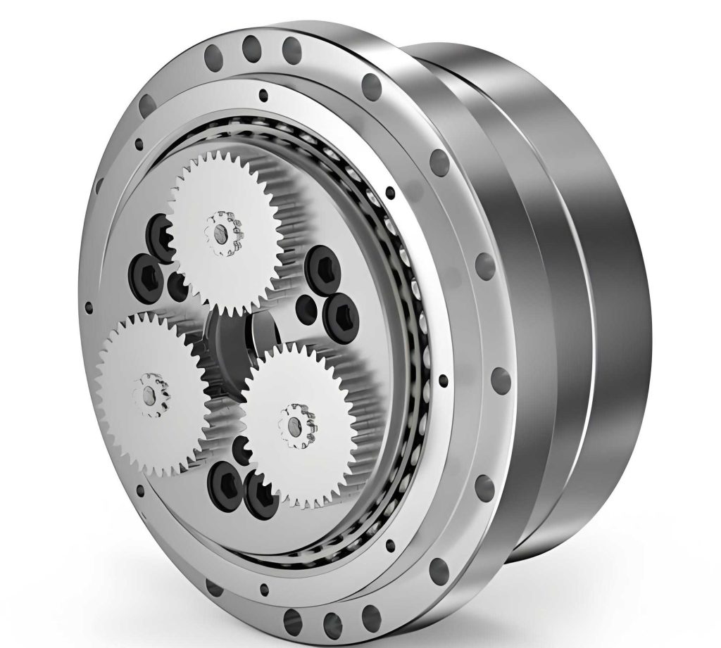
The exceptional performance of the rotary vector reducer stems from its sophisticated two-stage design. It integrates a first-stage planetary gear train with a second-stage cycloidal-pin wheel drive, resulting in a high reduction ratio within a remarkably rigid structure.
- First Stage (Planetary Gear Train): This stage consists of a sun gear (input), planetary gears, and a ring gear (fixed to the housing). The input shaft drives the sun gear, which meshes with multiple planetary gears. These planetary gears rotate within the fixed ring gear.
- Second Stage (Cycloidal Drive): This is the heart of the rotary vector reducer. The planetary gears are mounted on eccentric sections of crankshafts (also called pinions or eccentric shafts). As the planetary gears orbit, they impart an eccentric motion to these crankshafts. Two cycloidal disks (or摆线轮), offset by 180 degrees, are mounted on these crankshafts via bearings. These disks engage with a ring of stationary pin gears (or针轮) housed in the shell. The eccentric motion of the crankshafts causes the cycloidal disks to undergo a compound wobbling rotation. For each full revolution of the crankshaft, the cycloidal disk advances by one tooth relative to the pin gear ring. The output is taken from the support bearings of the crankshafts or directly from the carrier connected to the cycloidal disks.
This design inherently provides multiple tooth contacts in the cycloidal stage, leading to high load capacity and stiffness. The precision of this intricate mechanism, however, is susceptible to numerous influencing factors.
The transmission accuracy of a rotary vector reducer is primarily evaluated through two key metrics:
- Transmission Error (or Kinematic Error): This is the difference between the actual output rotation angle and the theoretical output angle for a given input. It affects the motion trajectory and smoothness of the robot.
- Backlash (or Hysteresis Error): This is the lost motion or the angular displacement the output shaft can have without the input shaft moving. It directly impacts the positioning precision and repeatability of the robotic system. For high-performance applications, modern rotary vector reducers are required to maintain backlash within 1 to 1.5 arc-minutes and transmission error within 1.0 arc-minute.
Fundamental Sources of Error in a Rotary Vector Reducer
Errors in a rotary vector reducer originate from three main phases: design and manufacturing, assembly, and operation. The following table categorizes the primary sources:
| Phase | Error Source | Primary Impact |
|---|---|---|
| Design & Manufacturing | Cycloidal disk tooth profile error (form, pitch) | Transmission Error, Backlash, Load distribution |
| Pin gear position and diameter error | Backlash, Contact stress | |
| Eccentricity error of the crankshaft | Transmission Error, Vibration | |
| Gear errors in the planetary stage | Minor contribution to overall error | |
| Bearing raceway and rolling element errors | Backlash, Stiffness variation | Assembly | Preload on bearings | Backlash, Stiffness, Life |
| Clearance fit between pins and housing bores | Backlash | |
| Meshing clearance adjustment (cycloid-pin) | Backlash | |
| Alignment of components | Transmission Error, Load distribution | Operation | Elastic deformation under load (teeth, bearings, shafts) | Transmission Error (non-linear) |
| Thermal expansion | Backlash variation | |
| Wear over time | Increasing Backlash and Transmission Error |
The Central Role of Cycloidal Disk Modification
The design and manufacturing of the cycloidal disk are arguably the most critical aspects determining the performance of a rotary vector reducer. In theory, a perfect cycloidal profile provides multiple simultaneous tooth contacts. However, in practice, perfect manufacturing and assembly are impossible. Furthermore, lubrication and thermal expansion require slight clearances. Therefore, the cycloidal tooth profile is intentionally modified or “corrected” from its theoretical geometry. This process, called modification or修形, is essential but introduces complexities.
The primary goals of modification are to:
1. Ensure proper lubrication by creating micro-gaps.
2. Compensate for manufacturing errors and assembly tolerances.
3. Accommodate elastic deformations under load to improve load distribution.
4. Ultimately, minimize backlash and transmission error under operating conditions.
The three classical methods for cycloid disk modification are:
- Offset Modification (等距修形): The theoretical cycloid is offset by a constant distance, either inward or outward. This changes the equidistant curve radius.
$$ R_p’ = R_p \pm \Delta R_p $$
where \( R_p \) is the original pin gear radius (or generating circle radius), and \( \Delta R_p \) is the offset amount. - Shift Modification (移距修形): The rolling circle used to generate the cycloid is shifted relative to the base circle. This alters the center distance in the generation process.
$$ a’ = a \pm \Delta a $$
where \( a \) is the standard eccentricity (center distance), and \( \Delta a \) is the shift amount. - Turning Angle Modification (转角修形): The starting angle of the cycloid generation is altered.
$$ \phi’ = \phi \pm \Delta \phi $$
where \( \phi \) is the standard rotation angle.
These methods are often used in combination. The choice and magnitude of modification directly affect the number of teeth in simultaneous contact and the load distribution among them. An unmodified or poorly modified profile may have nearly all teeth in contact under zero load, but under load, elastic deformations cause stress concentration on only 2-3 teeth. A well-designed modification aims to optimize the load-sharing characteristics under the expected operating load, improving stiffness and lifespan, while controlling the inherent clearance that contributes to backlash.
| Modification Method | Primary Effect on Clearance | Influence on Load Distribution |
|---|---|---|
| Offset (等距) | Creates a nearly uniform clearance along the flank. | Can significantly reduce the number of contact teeth if not combined with other methods. |
| Shift (移距) | Creates clearance that varies along the flank. | Effective in optimizing contact pattern under specific load conditions. |
| Turning Angle (转角) | Alters the meshing phase, affecting clearance distribution. | Often used for fine-tuning contact conditions and compensating for specific assembly errors. |
Quantitative Analysis of Elastic Deformation and Backlash
To achieve high accuracy, a static analysis considering elastic deformation is necessary. The total deformation at the cycloid-pin mesh, which influences the effective clearance, comes from two main sources:
- Contact Deformation between Cycloid Tooth and Pin (\(\delta_c\)): Modeled using Hertzian contact theory. For a cylindrical pin and a curved cycloid flank, the approximate approach can be used.
$$ \delta_c \approx \frac{2F}{\pi L} \cdot \frac{1-\nu^2}{E} \cdot \left( \ln\frac{4R_1R_2}{a^2} + 1 \right) $$
Where \(F\) is the contact force, \(L\) is the tooth width, \(\nu\) is Poisson’s ratio, \(E\) is Young’s modulus, \(R_1\) and \(R_2\) are the effective radii of curvature of the pin and cycloid tooth at the contact point, and \(a\) is the half-width of the contact area. - Contact Deformation between Pin and its Housing Bore (\(\delta_h\)): This is also a Hertzian contact problem between the pin (cylinder) and the housing bore (concave cylinder).
$$ \delta_h \approx \frac{2F}{\pi L} \cdot \frac{1-\nu^2}{E} \cdot \left( \ln\frac{4R_p R_h}{b^2} + 1 \right) $$
Where \(R_p\) is the pin radius, \(R_h\) is the housing bore radius, and \(b\) is the half-width of this contact area.
The combined deformation at the \(i\)-th pin is \(\delta_i = \delta_{c,i} + \delta_{h,i}\). Under operational load, the pins carrying the highest load will deform the most, effectively “taking up” some of the designed clearance. The goal of modification design is to create an initial clearance distribution such that under the designated rated load, the deformation brings most teeth into optimal contact, minimizing the maximum force on any single tooth and reducing the residual angular free play (backlash).
The total backlash \(B_T\) of a rotary vector reducer is a composite sum of clearances converted to angular displacement at the output shaft. It can be systematically broken down:
$$ B_T = \sqrt{B_{cycloid}^2 + B_{planetary}^2 + B_{bearing}^2 + B_{other}^2} $$
Where:
- \( B_{cycloid} \) is the backlash from the cycloid-pin mesh, dominantly influenced by modification design, pin position tolerance \( \Delta r_p \), and pin diameter tolerance \( \Delta d_p \).
$$ B_{cycloid} \propto \frac{\Delta r_p + k \cdot \Delta d_p}{R_{output}} $$
(\(k\) is a factor, \(R_{output}\) is the output radius) - \( B_{planetary} \) is the backlash from the first-stage planetary gears. This is typically less sensitive and can be controlled with standard gear tolerances.
- \( B_{bearing} \) is the backlash induced by clearances in the support bearings (e.g., crankshaft bearings, output bearings). Preloading these bearings is crucial to minimize this term.
- \( B_{other} \) includes contributions from fits and other assembly clearances.
Strategies for Controlling and Improving Transmission Accuracy
Based on the analysis of error sources, a multi-faceted approach is required to manufacture a high-precision rotary vector reducer.
| Control Area | Specific Strategy | Targeted Error Reduction |
|---|---|---|
| Design & Modification | Use computer simulation (FEA, multi-body dynamics) to optimize combined modification (offset+shift+angle) for specific load ranges. | Minimize transmission error and maximize contact teeth under load. |
| Design for manufacturability: Specify tolerances based on sensitivity analysis (e.g., strict tolerances for pin position, looser tolerances for planetary gears). | Control backlash sources cost-effectively. | |
| Manufacturing | High-precision grinding for cycloid disks (form grinding, CBN wheels). | Minimize cycloid tooth profile error. |
| Precision machining for pin housing bores (coordinates boring, honing). | Minimize pin position error \( \Delta r_p \). | |
| Use of high-precision, matched bearings. | Minimize \( B_{bearing} \). | |
| Assembly & Measurement | Implement selective assembly: match components (cycloid disks, pins, housings) based on actual measured dimensions. | Actively compensate for manufacturing variances to achieve consistent, minimal backlash. |
| Apply controlled preload to all critical bearing sets. | Eliminate bearing clearance, increase stiffness. | |
| Use laser interferometers or high-resolution encoders for final backlash and transmission error testing on every unit. | Ensure final product meets specification; data feedback for process control. | |
| Operational | Ensure proper lubrication with high-quality grease specified for precision gears. | Reduce wear, maintain consistent performance. |
| Consider thermal management in robot arm design to minimize thermal growth effects on reducer clearance. | Stable backlash over temperature range. |
In conclusion, the pursuit of excellence in rotary vector reducer performance is a systems engineering challenge. It requires an integrated focus from the initial design phase—particularly the sophisticated modification of the cycloidal profile—through ultra-precise manufacturing, and culminating in meticulous, measurement-driven assembly processes. The rotary vector reducer’s transmission accuracy is not dictated by a single factor but by the cumulative control of a myriad of interacting tolerances, deformations, and clearances. As the backbone of precision robotic motion, advancing the state-of-the-art in rotary vector reducer technology, through relentless refinement of these controlling factors, is fundamental to enabling the next generation of high-speed, heavy-payload, and exceptionally accurate industrial robots. The continuous improvement in modeling, material science, and metrology will further push the boundaries of what is achievable in the precision of the rotary vector reducer.