
In my experience working with precision mechanical systems, the reliable operation of power transmission components is paramount. Among these, the cycloidal drive, also known as a cycloidal speed reducer or cycloidal disc drive, stands out for its exceptional durability, high torque density, and compact design. I have observed its widespread application in demanding sectors such as robotics, material handling, mining, and aerospace. However, its robustness can sometimes lead to complacency in maintenance, which invariably results in premature failure and costly downtime. Therefore, a thorough understanding of its operation, coupled with a systematic approach to fault diagnosis, is essential for any engineer or technician. This guide consolidates my knowledge and field experience into a comprehensive resource for diagnosing and resolving issues with cycloidal drive units.
Fundamental Operating Principles of the Cycloidal Drive
To effectively diagnose faults, one must first understand the elegant yet simple principle behind the cycloidal drive. It is a specific type of epicyclic (planetary) gear system, falling under the K-H-V classification. The magic lies in its unique gearing geometry, which differs fundamentally from traditional involute gear systems.
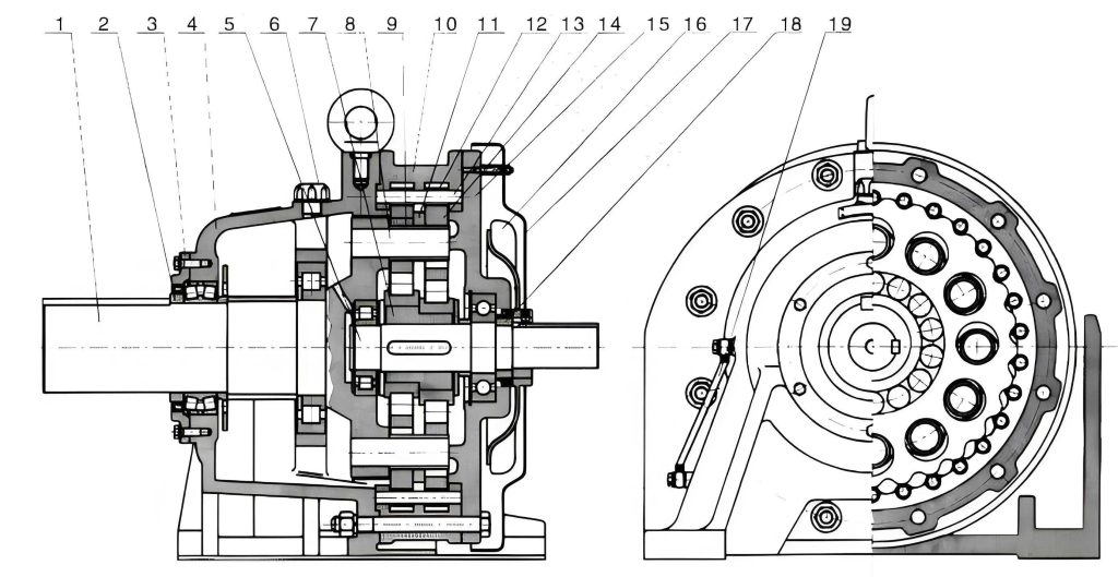
The core components of a single-stage cycloidal drive are:
- Input Shaft / Eccentric Crankshaft (H): This is the high-speed input. It incorporates one or two eccentric cam lobes that act as the planet carrier (the ‘H’ in K-H-V).
- Cycloidal Discs (K): Typically one or two discs (for force balancing) with a lobed tooth profile. These are mounted onto the eccentric lobes via heavy-duty roller bearings, known as turning arm bearings or cycloidal bearings. They are the planet gears.
- Ring of Stationary Pins (V): A circular array of cylindrical pins, often fitted with needle roller sleeves (pin sleeves), housed in the static casing. This ring acts as the fixed internal gear.
- Output Mechanism: Usually a series of holes in the cycloidal disc(s) that engage with a second set of pins (output pins) attached to the slow-speed output shaft. This mechanism converts the eccentric motion of the disc into concentric rotation of the output shaft.
The kinematic principle is one of “difference of teeth.” The number of lobes (N) on the cycloidal disc is always one (or a few) less than the number of stationary pins (N+1) in the ring. When the eccentric input shaft rotates, it causes the cycloidal disc to undergo a compound motion:
- Orbital Revolution: The disc orbits around the inside of the stationary pin ring, compelled by the eccentric input.
- Opposite Rotation: Because the pins prevent the disc from rotating freely, for every full orbital revolution of the input shaft, the disc itself rotates backwards by a small angle equal to the tooth difference.
The reduction ratio (i) of a standard single-stage cycloidal drive is given by:
$$ i = -\frac{N}{N_p – N} = -\frac{N}{1} $$
where \( N \) is the number of lobes on the cycloidal disc and \( N_p \) is the number of stationary pins. For the common case where \( N_p – N = 1 \), the ratio simplifies to \( i = -N \). The negative sign indicates the reversal of direction between input and the disc’s own rotation. The final output, through the pinned output mechanism, rotates in the same direction as the input but at the greatly reduced speed. This yields very high single-stage reduction ratios, often ranging from 6:1 to over 100:1.
The internal force transmission within a cycloidal drive is primarily through rolling contact and compression. A large number of lobes are simultaneously in contact with the pins (theoretically half of them), distributing the load over many contact points. This is the source of its high shock load tolerance and compact strength. The contact force between a cycloidal disc lobe and a pin sleeve can be modeled, though the full analysis is complex. A simplified static force on a pin (F_p) considering torque (T_out) and number of load-bearing lobes (n) is:
$$ F_p \approx \frac{2 \cdot T_{out}}{n \cdot D_p \cdot N} $$
where \( D_p \) is the pitch diameter of the stationary pin ring. This highlights how increasing the number of lobes (N) not only increases the ratio but also helps distribute the force, a key advantage of the cycloidal drive design.
Systematic Fault Diagnosis: Symptoms, Causes, and Remedies
Failures in a cycloidal drive rarely occur without warning. They manifest through distinct symptoms. A systematic approach involves monitoring these symptoms, understanding their root causes, and applying targeted corrective actions. Below, I detail the most common failure modes.
1. Excessive Operating Temperature
A sudden or gradual rise in case temperature beyond the normal operating range (typically 40-70°C above ambient, with 80°C+ being a critical warning) is a primary indicator of distress. The causes are often interrelated.
| Symptom | Potential Root Cause | Diagnostic Check | Corrective Action |
|---|---|---|---|
| Case too hot to touch, thermal shutdown. | Inadequate or Degraded Lubrication: Wrong oil type, low oil level, or oil breakdown due to aging, contamination, or overheating. | Check oil sight glass/level. Analyze oil sample for viscosity, contamination (metals, water). | Drain and flush. Refill with exact manufacturer-specified lubricant type and quantity. Establish regular oil change intervals. |
| Localized heating near input bearing area. | Turning Arm Bearing Failure: Inadequate lubrication, misalignment, or excessive shock loads cause bearing roller or raceway damage, leading to intense friction. | Listen for grinding/growling from input side. Check for axial/radial play in input shaft. Perform vibration analysis. | Disassemble unit. Replace the entire turning arm bearing assembly. Inspect eccentric cam for scoring. |
| General overheating under load. | Chronic Overloading: Operating beyond the drive’s rated torque capacity. | Review application torque requirements. Install and monitor a torque transducer on the output shaft. | Re-evaluate sizing. Select a cycloidal drive with a higher torque rating. Address shock loads with external dampers. |
| Overheating shortly after start-up. | Excessive Preload or Assembly Error: Incorrect shimming during reassembly creating internal binding. | Manually rotate input shaft before powering; feel for stiffness or uneven resistance. | Disassemble and reassemble following manufacturer’s shimming procedure precisely to achieve specified backlash. |
The relationship between heat generation and failure is often exponential. Friction from a failing bearing increases heat, which thins the oil, leading to more friction and wear. The heat balance for a cycloidal drive can be loosely conceptualized as:
$$ Q_{generated} = Q_{friction} + Q_{load\_loss} $$
$$ Q_{dissipated} = Q_{convection} + Q_{conduction} + Q_{radiation} $$
Failure occurs when \( Q_{generated} > Q_{dissipated} \) over a sustained period. The primary source of \( Q_{friction} \) in a healthy unit is the rolling friction in the turning arm bearings and pin sleeves.
2. Oil Leakage and Seepage
Leakage not only creates a mess but also leads to the lubrication issues described above, initiating a failure cascade. It points to seal failure or structural issues.
| Leak Location | Potential Root Cause | Diagnostic Check | Corrective Action |
|---|---|---|---|
| Around output shaft seal. | Shaft Misalignment: Angular or parallel misalignment between drive output and driven machine shaft causes whip and premature seal wear. | Use dial indicators to check alignment in both vertical and horizontal planes. Inspect seal lip for uneven wear. | Realign coupling to within manufacturer’s tolerance (typically < 0.05mm radial, < 0.1° angular). Replace shaft seal. |
| Across housing joint faces. | Damaged Gasket/O-ring or Loose Fasteners: Gasket degradation or uneven bolt torque. | Visually inspect gasket seam for seepage. Check fastener torque with a calibrated wrench. | Replace all static seals (gaskets, O-rings) during overhaul. Clean sealing surfaces. Re-torque fasteners in a star pattern to spec. |
| From input shaft seal. | Bearing Failure or High Internal Pressure: Failed input bearing creates heat/play, damaging seal. Breather vent clog can cause pressure build-up. | Check input bearing for play/noise. Ensure breather vent (if present) is clean and unobstructed. | Replace input bearing and seal. Clean or replace breather. |
| From pin or plug holes. | Failed Thread Sealant or Damaged Threads. | Tighten plug. If leakage persists, remove and inspect. | Apply appropriate thread sealant (e.g., liquid thread locker) and reinstall. Repair damaged threads with a Helicoil insert if necessary. |
3. Abnormal Noise and Vibration
Sound and vibration are excellent diagnostic tools. Changes in the acoustic signature of a cycloidal drive often provide the earliest warning of mechanical degradation.
| Type of Noise/Vibration | Potential Root Cause | Frequency Domain Clue | Corrective Action |
|---|---|---|---|
| High-frequency whining or screeching. | Lubrication Starvation at high-speed contacts (pin sleeves, turning arm bearings). | Broadband high-frequency increase in vibration spectrum. | Immediately check and correct oil level/condition. Inspect for scored surfaces upon disassembly. |
| Repetitive knocking or clicking, synchronous with input shaft speed. | Damaged Rolling Elements: A chipped or spalled roller in the turning arm bearing. | Spike at the Ball Pass Frequency Outer Race (BPFO) or Inner Race (BPFI) of the turning arm bearing. | Replace the turning arm bearing assembly. Analyze oil for metallic debris. |
| Irregular grinding or growling. | Severe Wear or Pitting on cycloidal disc lobes or pin sleeves. | Increased vibration at the gear mesh frequency (\( f_{mesh} = f_{input} \times N \)) and its harmonics, with sidebands. | Complete overhaul. Replace cycloidal disc(s) and the entire stationary pin assembly. Root cause analysis for overload or lubrication failure is critical. |
| Low-frequency beating or wobble felt at output. | Severe Misalignment or Bent Output Shaft. | High vibration at 1x and 2x output shaft rotational frequency. | Stop operation. Perform precision alignment check. Replace output shaft if bent. |
| Backlash-induced “clunk” on direction reversal. | Excessive Wear in output mechanism pins/holes or incorrect backlash adjustment. | High transient peaks on torque or acceleration trace during reversal. | Measure operational backlash. If excessive, disassemble and inspect output pins and disc holes for ovalization. Replace worn parts and reset backlash per manual. |
The gear mesh frequency (\( f_{mesh} \)) is a critical parameter for vibration analysis on a cycloidal drive. It is calculated as:
$$ f_{mesh} = \frac{RPM_{input}}{60} \times N $$
where \( RPM_{input} \) is the input speed in revolutions per minute, and \( N \) is the number of cycloidal disc lobes. Changes in the amplitude or harmonic pattern of this frequency indicate deteriorating gear mesh health.
Advanced Diagnostic Procedures and Preventive Strategies
Moving beyond reactive repairs, a proactive maintenance philosophy for cycloidal drive systems involves scheduled monitoring and data-driven decisions.
Vibration Analysis Protocol
Establish a baseline vibration spectrum when the drive is new and healthy. Subsequent periodic measurements (e.g., quarterly) should be compared against this baseline and alarm thresholds.
- Sensor Placement: Triaxial accelerometers on the input bearing housing, output bearing housing, and the main casing.
- Key Frequencies to Monitor:
- Input shaft RPM and harmonics.
- Turning Arm Bearing frequencies (BPFI, BPFO, Ball Spin Frequency).
- Gear Mesh Frequency (\( f_{mesh} \)) and its harmonics.
- Output shaft RPM and harmonics.
- Trending Parameters: Overall Velocity (RMS), Crest Factor, and Kurtosis can indicate developing bearing faults. Envelope Demodulation is particularly effective for early bearing defect detection in the noisy environment of a cycloidal drive.
Oil Analysis Program
Regular oil sampling is a window into the internal health of the cycloidal drive.
- Physical Tests: Viscosity, water content, particle count.
- Spectroscopic Analysis: Detects trace metals (Fe, Cr, Ni from bearings; Cu from bushings) indicating wear rates.
- Analytical Ferrography: Examines the size, shape, and composition of wear particles to determine the wear mechanism (e.g., rubbing, cutting, fatigue spalling).
Thermographic Imaging
An infrared camera can quickly identify hot spots caused by misalignment, failing bearings, or internal friction before they become critical. Compare the thermal profile against a known good baseline.
Preventive Maintenance Schedule
A proactive schedule is far less costly than unplanned downtime. The following table outlines a generic framework, which must be adapted to the specific manufacturer’s recommendations and operating environment.
| Task | Daily/Weekly | Monthly | 6 Months | Annually or per Operating Hours |
|---|---|---|---|---|
| Visual Inspection | Check for leaks, unusual noise. | Inspect for loose mounting bolts, coupling condition. | Detailed inspection of seals, breathers. | Full external inspection. |
| Temperature Check | Touch check for overheating. | Use IR thermometer on bearing housings. | Record temperatures at standard points. | Thermographic survey. |
| Vibration Monitoring | – | Route-based simple measurements. | Detailed spectrum analysis. | Comprehensive analysis with report. |
| Lubrication | Check oil level sight glass. | – | Take oil sample for analysis. | Drain, flush, and refill with new oil (or as per oil analysis results). |
| Alignment Check | – | – | Quick laser alignment check. | Full precision realignment. |
| Operational Test | Listen for changes in sound. | – | Check for excessive backlash or play. | Perform full load test if possible. |
Conclusion
The cycloidal drive is an engineering marvel that delivers exceptional performance in a small package. Its reliability, however, is not unconditional. It is predicated on correct installation, proper lubrication, operation within design limits, and vigilant maintenance. From my perspective, the most common failures—overheating, leakage, and abnormal noise—are almost always symptoms of a breach in one of these fundamental requirements. By understanding the kinematics and force transmission of the cycloidal drive, engineers can move from simply replacing parts to performing true root cause analysis. Implementing a disciplined regimen of vibration analysis, oil condition monitoring, and thermal checks transforms maintenance from a reactive cost center into a proactive strategy for maximizing asset life and plant productivity. The compactness of the cycloidal drive should never be an excuse for neglecting its care; rather, its sophisticated internal mechanics demand and deserve a correspondingly sophisticated approach to fault diagnosis and health management.