
In my years of experience working with precision mechanical systems, I have found that the cycloidal drive, a type of cycloidal speed reducer, is a cornerstone in many industrial applications due to its compact design, high efficiency, and robust load-bearing capacity. However, its performance and longevity are heavily dependent on proper maintenance and timely fault diagnosis. This article delves into the operational principles of the cycloidal drive, common failure modes, and comprehensive treatment strategies, aiming to equip engineers with the knowledge to ensure optimal functionality. I will emphasize the use of tables and mathematical formulations to encapsulate key concepts, ensuring clarity and practicality. Throughout this discussion, the term ‘cycloidal drive’ will be frequently reiterated to reinforce its centrality in this context.
The cycloidal drive, often referred to as a cycloidal speed reducer, operates on the principle of epicyclic or planetary gear transmission, specifically a K-H-V type arrangement. This mechanism involves a high-speed input, a set of cycloidal disks (planetary gears), and a stationary ring of pins (the ring gear). The unique motion derives from the cycloidal profile of the disks, which mesh with the pins to produce a significant speed reduction in a single stage. The fundamental advantage lies in its multi-tooth contact, which distributes loads evenly, leading to high torque capacity and smooth operation. To understand this better, let’s examine the kinematics mathematically.
The transmission ratio of a cycloidal drive is a critical parameter. For a standard configuration where the cycloidal disk has \( Z_c \) teeth and the pin ring has \( Z_p \) pins, with the tooth difference \( \Delta Z = Z_p – Z_c \) typically being 1, 2, 3, or 4, the reduction ratio \( i \) can be expressed as:
$$ i = -\frac{Z_p}{\Delta Z} $$
Here, the negative sign indicates that the output rotation is in the opposite direction to the input. For instance, if \( Z_p = 40 \) and \( \Delta Z = 1 \), then \( i = -40 \), meaning the output shaft rotates once for every 40 rotations of the input shaft, but in reverse. The absolute value \( |i| \) is often cited as the reduction ratio. This high ratio in a compact space is a hallmark of the cycloidal drive. The cycloidal profile itself is generated by a curtate epicycloid or hypocycloid curve, defined parametrically. For a generating circle of radius \( r_g \) rolling on a base circle of radius \( r_b \), the coordinates of a point on the cycloid are:
$$ x = (r_b + r_g) \cos \theta – e \cos\left(\frac{r_b + r_g}{r_g} \theta\right) $$
$$ y = (r_b + r_g) \sin \theta – e \sin\left(\frac{r_b + r_g}{r_g} \theta\right) $$
where \( e \) is the eccentricity of the generating point, and \( \theta \) is the rotation angle. This curve ensures that multiple teeth are in contact simultaneously, enhancing load distribution. The following table summarizes key geometric parameters in a typical cycloidal drive design:
| Parameter | Symbol | Typical Range | Description |
|---|---|---|---|
| Number of Pin Teeth | \( Z_p \) | 20-100 | Fixed ring gear pins |
| Number of Cycloid Disk Teeth | \( Z_c \) | \( Z_p – \Delta Z \) | Planetary gear teeth |
| Tooth Difference | \( \Delta Z \) | 1-4 | Determines reduction ratio |
| Eccentricity | \( e \) | 1-5 mm | Offset in crankshaft |
| Pin Circle Radius | \( R_p \) | 50-500 mm | Radius to pin centers |
| Cycloid Disk Radius | \( R_c \) | \( R_p – e \) | Reference for tooth profile |
To visualize the internal assembly of a cycloidal drive, consider the following image, which depicts a cross-sectional view of a cycloidal speed reducer, highlighting the key components such as the input shaft, cycloidal disks, pin ring, and output mechanism.
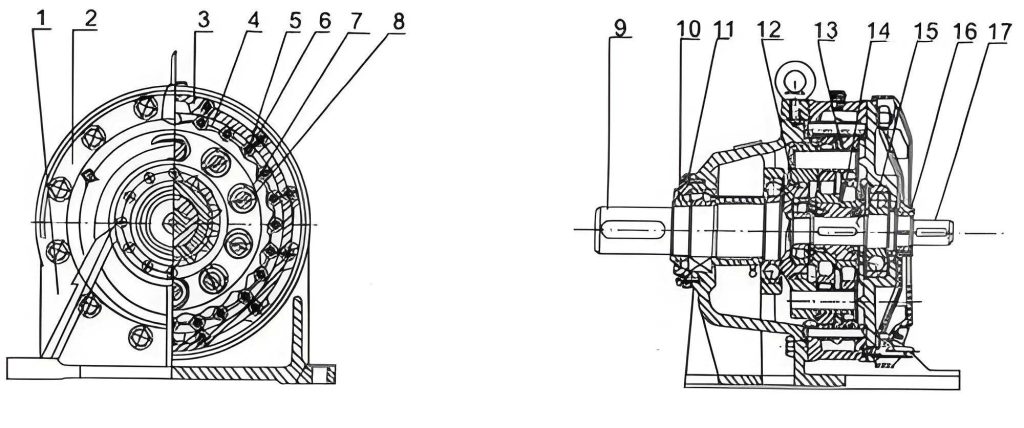
In operation, the input shaft rotates an eccentric cam or crankshaft, which carries the cycloidal disks. As the disks orbit around the pin ring, their cycloidal teeth engage with the pins, causing the disks to rotate slightly relative to the housing. This rotation is transmitted to the output shaft via a wobble plate or pin-slot mechanism. The dynamic forces involved can be analyzed using torque balance equations. If \( T_{in} \) is the input torque and \( T_{out} \) is the output torque, neglecting losses, the relationship is:
$$ T_{out} = i \cdot T_{in} $$
However, efficiency \( \eta \) must be accounted for in practice, typically ranging from 90% to 98% for a cycloidal drive, leading to:
$$ T_{out} = \eta \cdot i \cdot T_{in} $$
The efficiency is influenced by factors like lubrication, manufacturing precision, and alignment. This foundational understanding sets the stage for diagnosing issues that arise during the lifecycle of a cycloidal drive.
Faults in a cycloidal drive can manifest in various ways, often interlinked with operational conditions. Based on my field observations, the most prevalent issues include abnormal temperature rise, oil leakage, and excessive noise. Each fault has distinct root causes and remediation paths. I will elaborate on these, using tables to condense the information for quick reference, while expanding on the underlying mechanics.
1. Abnormal Temperature Rise
When a cycloidal drive operates at temperatures exceeding 80°C, it signals potential damage. The heat generation primarily stems from friction losses, which can be modeled using the power loss equation:
$$ P_{loss} = (1 – \eta) \cdot P_{in} $$
where \( P_{in} \) is the input power. The temperature rise \( \Delta T \) over time \( t \) can be approximated by:
$$ \Delta T = \frac{P_{loss} \cdot t}{C \cdot m} $$
with \( C \) being the specific heat capacity of the housing material and \( m \) its mass. Common causes and solutions are tabulated below:
| Cause | Diagnostic Indicators | Solution | Preventive Measures |
|---|---|---|---|
| Degraded or incorrect lubricant | High viscosity index drop, discoloration | Replace with manufacturer-specified oil (e.g., ISO VG 320) | Regular oil analysis; adhere to change intervals |
| Insufficient lubrication of eccentric bearings | Dry spots on bearings, increased friction | Refill oil to recommended level; ensure proper circulation | Install sight glasses; monitor oil levels weekly |
| Worn or damaged eccentric bearings | Vibration spikes, metallic debris in oil | Disassemble drive; replace bearings with precision grades | Use condition monitoring; avoid shock loads |
| Overloading beyond rated capacity | Current draw spikes, thermal imaging hotspots | Reduce load to within nameplate specifications | Implement torque limiters; verify application torque requirements |
| Misalignment with driven equipment | Uneven wear patterns on cycloidal disks | Realign shafts to within 0.05 mm tolerance | Use laser alignment tools during installation |
In-depth, the lubricant’s role is critical. The cycloidal drive relies on a thin film to separate moving parts. The minimum film thickness \( h_{min} \) in journal bearings can be estimated with the Reynolds equation, but practically, selecting oil with extreme pressure (EP) additives is key. For instance, a common recommendation is synthetic PAO-based lubricants with anti-wear agents. Overloading often ties to torque calculations; the allowable torque \( T_{allow} \) should satisfy:
$$ T_{allow} \geq \frac{T_{applied} \cdot SF}{i} $$
where \( SF \) is a service factor (typically 1.5 for cycloidal drives in heavy duty).
2. Oil Leakage and Seepage
Leakage compromises lubrication and invites contamination. The primary seals in a cycloidal drive include shaft seals, housing gaskets, and O-rings. Failure modes often relate to pressure differentials and wear. The leakage rate \( Q \) through a seal gap can be modeled by:
$$ Q = \frac{\pi \cdot d \cdot h^3 \cdot \Delta P}{12 \cdot \mu \cdot L} $$
where \( d \) is seal diameter, \( h \) gap height, \( \Delta P \) pressure difference, \( \mu \) oil viscosity, and \( L \) seal length. Causes and fixes are summarized:
| Cause | Diagnostic Indicators | Solution | Preventive Measures |
|---|---|---|---|
| Shaft misalignment causing seal wear | Eccentric wear on seal lip, oil along shaft | Realign output shaft; replace shaft seal with double-lipped design | Perform alignment checks quarterly; use flexible couplings |
| Worn gaskets or O-rings | Oil at housing joints, compression set visible | Replace with high-temperature fluoroelastomer seals | Inspect seals during maintenance; store seals properly |
| Loose housing bolts | Oil seepage from flange interfaces | Torque bolts to spec (e.g., 50-70 Nm) with crisscross pattern | Use threadlocker; implement bolt tension monitoring |
| Excessive internal pressure from temperature | Leakage after prolonged operation | Install breather vents; ensure proper venting | Check breathers regularly; avoid overfilling oil |
| Damage to sealing surfaces | Scratches or corrosion on shafts/housing | Polish surfaces; apply sealant if needed | Protect from corrosion; use hardened shafts |
Seal selection is vital. For cycloidal drives in dusty environments, labyrinth seals or magnetic seals might be considered. The pressure build-up can be mitigated by ensuring the breather is clear, as per the ideal gas law: \( P \propto T \), so temperature control reduces pressure.
3. Excessive Noise and Vibration
Unusual noises indicate mechanical distress. Vibration analysis can pinpoint issues. The sound pressure level \( L_p \) in decibels relates to vibration amplitude \( A \) by:
$$ L_p \approx 20 \log_{10}\left(\frac{A}{A_0}\right) $$
where \( A_0 \) is a reference. Common sources include meshing impacts and bearing defects. The table below outlines details:
| Cause | Diagnostic Indicators | Solution | Preventive Measures |
|---|---|---|---|
| Misalignment with base or driven unit | High vibration at 1x and 2x running frequency | Re-align using dial indicators; grout base properly | Use vibration sensors; conduct alignment after any disturbance |
| Worn or damaged internal parts (pins, disks) | Clicking or grinding sounds, debris in oil | Disassemble; replace worn pins and cycloidal disks as a set | Perform oil analysis for wear metals; avoid contamination |
| Loose fasteners or housing components | Rattling noises, visible movement | Tighten all fasteners; check for cracks | Implement torque audits; use locking washers |
| Inadequate lubrication leading to dry contact | Squealing noises, increased temperature | Re-lubricate; ensure oil reaches all gears | Automatic lubrication systems; monitor oil flow |
| Unbalance in rotating elements | Vibration at specific frequencies | Dynamic balancing of input shaft and disks | Balance during assembly; check after repairs |
The meshing frequency \( f_m \) of a cycloidal drive is given by:
$$ f_m = \frac{Z_c \cdot n_{in}}{60} $$
where \( n_{in} \) is input speed in RPM. Abnormal peaks at this frequency in vibration spectra indicate tooth engagement issues. Bearing defect frequencies can be calculated based on bearing geometry, aiding diagnosis.
Beyond these primary faults, other issues like reduced efficiency or sudden stoppage may occur. For efficiency drops, the power loss can be attributed to churning losses in oil, modeled as:
$$ P_{churn} = k \cdot \rho \cdot \omega^3 \cdot D^5 $$
where \( k \) is a constant, \( \rho \) oil density, \( \omega \) angular velocity, and \( D \) characteristic length. Regular maintenance schedules are essential. I recommend a proactive approach with condition-based monitoring. The following table provides a maintenance checklist for cycloidal drives:
| Activity | Frequency | Procedure | Tools/Standards |
|---|---|---|---|
| Oil level check | Weekly | Visual inspection via sight glass; top-up if needed | ISO viscosity grade chart |
| Vibration analysis | Monthly | Measure RMS velocity; compare to baseline | Vibration meter, ISO 10816 |
| Thermal imaging | Quarterly | Scan housing for hotspots >70°C | Infrared camera |
| Oil change | Every 4000 hours or annually | Drain old oil; flush; refill with fresh oil | Manufacturer’s oil spec |
| Alignment check | After any disturbance | Laser alignment of input/output shafts | Alignment tool, tolerance 0.05 mm |
| Seal inspection | During oil change | Check for wear, cracks, or leaks | Seal measurement gauge |
| Fastener torque audit | Bi-annually | Verify bolt tightness with torque wrench | Torque specifications table |
Installation precision cannot be overstated. The cycloidal drive must be mounted on a rigid, flat base to prevent distortion. The alignment error \( \delta \) should satisfy:
$$ \delta \leq 0.0005 \cdot L $$
where \( L \) is the distance between coupling halves. Also, consider environmental factors; for example, in mining, dust ingress can accelerate wear. Using sealed units or air purges might be necessary.
In terms of design enhancements, modern cycloidal drives incorporate materials like case-hardened steel for cycloidal disks and ceramic-coated pins to reduce friction. The contact stress \( \sigma_c \) between a pin and cycloid tooth can be calculated using Hertzian theory:
$$ \sigma_c = \sqrt{\frac{F \cdot E^*}{\pi \cdot R^*}} $$
where \( F \) is the load per tooth, \( E^* \) the effective elastic modulus, and \( R^* \) the effective radius. Optimizing this stress extends service life. Furthermore, predictive maintenance using IoT sensors can track parameters like temperature, vibration, and oil quality in real-time, enabling early fault detection.
To summarize, the cycloidal drive is a robust transmission solution, but its reliability hinges on understanding its mechanics and failure modes. Through systematic diagnosis—leveraging formulas for performance prediction and tables for actionable insights—operators can preempt failures and maximize uptime. Emphasizing proper lubrication, alignment, and load management will ensure that the cycloidal drive delivers its renowned efficiency and durability across diverse industries. Continuous learning and adaptation of best practices are key, as each application of the cycloidal drive presents unique challenges that require tailored solutions.