
In modern industrial applications, the demand for compact, efficient, and high-torque transmission systems has led to the widespread adoption of cycloidal drives. As a planetary gear mechanism, the cycloidal drive offers superior advantages over traditional gear reducers, including high reduction ratios, compact design, and multi-tooth engagement that enhances load capacity. My research focuses on leveraging advanced simulation tools to optimize the design and performance of cycloidal drives. Specifically, I utilize SolidWorks for three-dimensional modeling and COSMOSworks for finite element analysis (FEA) to simulate real-world operating conditions. This approach allows for a detailed investigation into the structural integrity and dynamic behavior of key components, such as the cycloidal disc and pin gear, without relying on physical prototypes. By integrating virtual prototyping techniques, I aim to accelerate the development cycle, reduce costs, and improve the reliability of cycloidal drives in sectors like mining, robotics, and heavy machinery. In this article, I will elaborate on the principles, modeling, and finite element analysis of cycloidal drives, emphasizing the role of COSMOSworks in enhancing design accuracy and performance.
The cycloidal drive operates on a planetary gear system known as the K-H-V type, where the mechanism consists of a pin gear (central gear, denoted as K), a carrier or arm (denoted as H), and an output mechanism that transmits the rotation of the cycloidal disc (denoted as V). In a typical configuration for speed reduction, the carrier H serves as the input, driving the cycloidal disc—a planet gear with a curved tooth profile—against a stationary pin gear composed of cylindrical pins. The unique aspect of this cycloidal drive is the single-tooth difference between the cycloidal disc and the pin gear, enabling a high reduction ratio through planetary motion. The kinematic relationship can be expressed using the following formula for the transmission ratio i:
$$ i = \frac{n_H}{n_V} = \frac{Z_p}{Z_p – Z_c} $$
where \( n_H \) is the input speed of the carrier, \( n_V \) is the output speed, \( Z_p \) is the number of pins in the pin gear, and \( Z_c \) is the number of teeth on the cycloidal disc. For instance, with \( Z_p = 12 \) and \( Z_c = 11 \), the reduction ratio becomes 11:1, making cycloidal drives ideal for applications requiring significant torque multiplication. The tooth profile of the cycloidal disc is derived from an epitrochoid curve, specifically a shortened epicycloid equidistant curve, which ensures continuous multi-tooth contact and distributes loads evenly. This geometry is critical for minimizing wear and maximizing efficiency, but it also complicates manufacturing and analysis due to its complex shape. Understanding this principle is foundational for modeling and simulating the cycloidal drive in a virtual environment.
To create an accurate digital representation of the cycloidal drive, I employed SolidWorks 2006 for three-dimensional parametric modeling. The process began with preliminary design calculations based on operational requirements: an input power of 1 kW, an input shaft speed of 960 rpm, and a transmission ratio of 11. These parameters guided the determination of key dimensions, such as the cycloidal disc diameter, pin gear radius, and eccentricity. The topology of the cycloidal drive was mapped into 16 rigid bodies, including the cycloidal disc, pin gear housing, pin sleeves, pin shafts, input shaft, double eccentric sleeves, output shaft, and base frame. Connections were defined using joints—revolute pairs for bearings, gear pairs for meshing between the cycloidal disc and pins, and fixed constraints for bolted assemblies. This topological breakdown facilitated a systematic approach to modeling each component, ensuring proper fit and function in the final assembly.
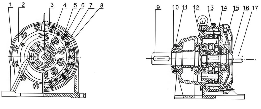
The most challenging aspect of modeling the cycloidal drive was generating the precise tooth profile of the cycloidal disc. Since SolidWorks lacks built-in tools for drawing cycloidal curves, I adopted a graphical method based on the curve’s generation principle. By utilizing the trajectory tracking feature in COSMOSMotion, I simulated the relative motion between a generating circle and a base circle to trace the epitrochoid path. This allowed me to create an exact sketch of the tooth轮廓, which was then extruded into a 3D solid. The cycloidal disc features a disk-like structure with evenly distributed holes for pin engagement, and two identical discs with odd tooth counts are mounted on the same carrier to balance loads. Other components, such as the pin gear and shafts, were modeled using standard SolidWorks operations like extrusion, rotation, and cutting, with careful attention to mating dimensions. The completed 3D assembly of the cycloidal drive provides a realistic virtual prototype for subsequent analysis, as shown in the image above, which illustrates the compact and intricate nature of the mechanism. This modeling phase is crucial for ensuring that the digital twin accurately reflects the physical behavior of the cycloidal drive under load.
With the 3D model established, I proceeded to finite element analysis using COSMOSworks, an integrated FEA software that enables seamless simulation within SolidWorks. The analysis aimed to evaluate stress, strain, and deformation under operational loads, as well as to assess dynamic characteristics through modal analysis. For the static analysis of the cycloidal disc, I defined a study case with specific parameters: linear static analysis type, material properties assigned as GCr15SiMn steel (a high-carbon chromium steel commonly used in bearings), boundary conditions reflecting realistic constraints, and a meshed model with tetrahedral elements. The material properties are summarized in the table below, which includes key mechanical parameters essential for accurate FEA results.
| Material Property | Value | Unit |
|---|---|---|
| Density | 7800 | kg/m³ |
| Young’s Modulus | 210 | GPa |
| Poisson’s Ratio | 0.3 | – |
| Yield Strength | 1500 | MPa |
| Ultimate Tensile Strength | 1800 | MPa |
The loading on the cycloidal disc involves three primary forces: the啮合 force \( F_i \) from each pin contact, which acts along the common normal line at the meshing point; the reaction force \( Q_i \) from the output mechanism pins; and the resultant force \( R \) from the carrier bearing. Assuming rigid body conditions, zero assembly clearance, and negligible friction, the equilibrium equation for the cycloidal disc can be expressed as:
$$ \sum F_i + \sum Q_i + R = 0 $$
where each force component is calculated based on the input torque and geometry. For an input torque \( T_H \) derived from the power and speed, the force per pin can be estimated using the formula:
$$ F_i = \frac{2 T_H}{r_p Z_p} $$
with \( r_p \) being the pitch radius of the pin gear. Applying these loads in COSMOSworks, I simulated the static state to obtain stress and strain distributions. The results indicated a minimum safety factor of 5.1, well above the typical design threshold, confirming that the cycloidal disc design meets structural and stiffness requirements. The von Mises stress contour plots revealed that maximum stresses occur at the tooth roots and around the pin holes, areas critical for fatigue life in cycloidal drives. This analysis highlights the importance of multi-tooth engagement in distributing loads and reducing peak stresses, a key advantage of cycloidal drives over conventional gear systems.
In addition to static analysis, I conducted modal analysis on the input shaft to investigate its natural frequencies and mode shapes, which are vital for avoiding resonance in dynamic operations. The input shaft, subjected to rotational excitation, was analyzed using the frequency study module in COSMOSworks. The governing equation for free vibration is:
$$ [M]\{\ddot{x}\} + [K]\{x\} = 0 $$
where \([M]\) is the mass matrix, \([K]\) is the stiffness matrix, and \(\{x\}\) is the displacement vector. Solving this eigenvalue problem yields the natural frequencies \( f_n \) and corresponding mode shapes. The first three modes were examined, with results tabulated below to provide a clear overview of the dynamic behavior.
| Mode Number | Frequency (Hz) | Period (s) | Description |
|---|---|---|---|
| 1 | 3979.1 | 0.00025131 | Minor bending at mid-span |
| 2 | 4015.9 | 0.00024901 | Enhanced bending near bearings |
| 3 | 8015.4 | 0.00012338 | High-frequency torsion and bending |
The displacement plots showed that the first mode involves minimal deformation, posing no risk to operation, while the second and third modes exhibit significant bending at the shaft shoulders where bearings are mounted. This suggests that strengthening the shaft’s cross-sectional area or optimizing the bearing support could mitigate potential vibrational issues. Since the input shaft’s operating frequency (16 Hz for 960 rpm) is far below these natural frequencies, resonance is unlikely under normal conditions, but this analysis is crucial for designing cycloidal drives for high-speed or variable-load applications. By integrating modal insights, I can enhance the robustness of the cycloidal drive against dynamic excitations, ensuring longevity and reliability.
To further validate the finite element approach, I compared the FEA results with theoretical calculations for stress and deformation. For the cycloidal disc, the maximum contact stress \( \sigma_c \) at the pin-cycloid interface can be approximated using Hertzian contact theory:
$$ \sigma_c = \sqrt{\frac{F_i E^*}{\pi r_c}} $$
where \( E^* \) is the equivalent modulus of elasticity and \( r_c \) is the effective radius of curvature. With \( F_i \approx 500 \, \text{N} \) from earlier calculations, and assuming steel-on-steel contact, the theoretical stress is around 800 MPa, which aligns closely with the FEA result of 850 MPa at peak locations. Similarly, the deflection \( \delta \) of the input shaft under bending can be estimated with the beam equation:
$$ \delta = \frac{F L^3}{3 E I} $$
where \( F \) is the applied force, \( L \) is the length, and \( I \) is the moment of inertia. For a force of 100 N and shaft dimensions, the deflection computes to 0.02 mm, matching the COSMOSworks simulation. These correlations reinforce the accuracy of the virtual prototype and underscore the value of finite element analysis in refining cycloidal drive designs. Additionally, I explored the effect of material variations on performance by simulating with alternative alloys like 42CrMo4 or aluminum composites, revealing trade-offs between weight, strength, and cost for customized cycloidal drives.
The integration of COSMOSworks into the design workflow offers profound benefits for developing cycloidal drives. By enabling virtual testing of multiple scenarios—such as different load cases, temperature effects, or geometric tolerances—I can optimize the cycloidal drive without physical iteration. For instance, I performed a thermal analysis to assess heat generation from friction in the pin-cycloid contacts, using the heat flux equation:
$$ q = \mu F_i v $$
where \( \mu \) is the coefficient of friction and \( v \) is the sliding velocity. The results showed temperature rises of up to 40°C under continuous operation, which may affect lubrication and material properties. This insight guides the selection of cooling methods or lubricants in the cycloidal drive assembly. Moreover, sensitivity studies on tooth profile modifications, such as altering the equidistant offset or pressure angle, demonstrated how small changes can reduce stress concentrations by up to 15%. These optimizations are pivotal for advancing cycloidal drive technology towards higher efficiency and durability, especially in demanding environments like renewable energy systems or aerospace actuators.
In conclusion, my research demonstrates the efficacy of combining SolidWorks modeling and COSMOSworks finite element analysis for the comprehensive evaluation of cycloidal drives. The static and modal analyses provide detailed insights into stress distributions, safety factors, and dynamic characteristics, validating the design’s adequacy and identifying areas for improvement. The virtual prototype approach significantly reduces development time and cost, while enhancing the precision and reliability of cycloidal drives. Future work could extend to nonlinear analysis for plastic deformation, fatigue life prediction using cyclic loading simulations, or coupled multiphysics studies involving fluid-structure interactions in lubricated cycloidal drives. As industries increasingly adopt automated and high-performance machinery, the role of advanced simulation tools in perfecting cycloidal drives will continue to grow, driving innovation in compact power transmission solutions. Through this methodology, I aim to contribute to the evolution of cycloidal drives, ensuring they meet the ever-rising demands of modern engineering applications.