
In modern industrial applications, particularly in robotics and precision manufacturing equipment, the RV reducer plays a critical role due to its high performance and reliability. As a type of rotary vector reducer, the RV reducer is widely adopted for its compact design, high torque capacity, and excellent positioning accuracy. However, with increasing demands for smoother operation and reduced vibration, understanding the dynamic characteristics of the RV reducer through modal analysis has become essential. In this article, I will explore the modal simulation of key components in the RV reducer using finite element methods, focusing on steps such as modeling, material property assignment, mesh generation, and boundary condition setting. The goal is to provide insights that can enhance the design and performance of the RV reducer, ultimately contributing to industrial upgrade and quality of life preservation.
The RV reducer operates based on RV transmission principles, which combine planetary gear stages with a cycloidal drive mechanism. Before delving into modal analysis, it is crucial to understand the distinctive features of RV transmission that make the RV reducer so effective. These characteristics not only influence the overall performance but also impact the vibrational behavior that we aim to analyze. Below, I summarize the key features of RV transmission in a table for clarity.
| Characteristic | Description |
|---|---|
| Wide Range of Transmission Ratio | The RV reducer offers a broad spectrum of transmission ratios, typically ranging from 30 to over 200, allowing for versatile applications in various speed reduction scenarios. This is achieved through the multi-stage gearing system inherent in the RV reducer design. |
| High Torsional Stiffness | Due to the rigid large disk at the left end of the planetary carrier, which facilitates output, the torsional stiffness of the RV reducer is significantly higher than that of conventional cycloidal pin-wheel planetary reducers. This stiffness minimizes backlash and enhances precision in motion control. |
| Rational Design and Assembly Accuracy | The RV reducer is engineered with a rational layout that minimizes alignment issues during assembly. This design precision ensures consistent performance and reduces the likelihood of vibrational anomalies in the RV reducer. |
| High Transmission Efficiency | With efficiency often exceeding 90%, the RV reducer minimizes energy losses, making it suitable for high-duty cycles. This efficiency stems from the optimized gear meshing and reduced friction within the RV reducer mechanism. |
These features collectively contribute to the widespread adoption of the RV reducer in fields such as industrial robots, CNC machines, and aerospace equipment. However, to further improve the RV reducer’s performance, especially in terms of vibration suppression, a detailed modal analysis is necessary. Modal analysis helps identify natural frequencies and mode shapes, which are vital for avoiding resonance and ensuring operational stability. In the following sections, I will outline the step-by-step process for conducting a modal simulation of the RV reducer’s key components using finite element software.
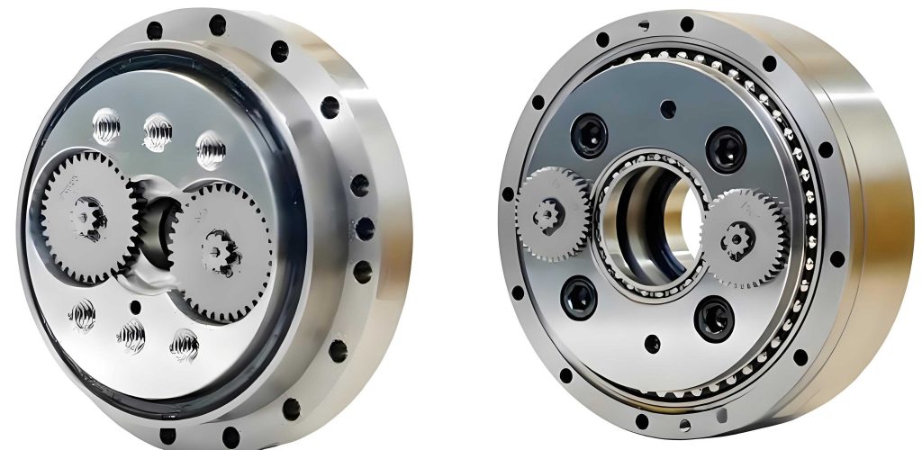
The modal analysis of the RV reducer begins with scientific modeling, where accurate geometric representation is paramount. I utilize parametric design software, such as Pro/ENGINEER (Pro/E), to create detailed 3D models of the RV reducer components, including the planetary gears, crankshaft, and planetary carrier. Parametric modeling allows for easy modification of design parameters, which is essential for iterative optimization of the RV reducer. For instance, the involute gear parameters must be defined precisely to ensure realistic behavior. Below is a table summarizing the key design parameters for the involute gears used in the RV reducer.
| Parameter | Value |
|---|---|
| Number of Teeth (z) | 45 |
| Pressure Angle (α) | 20° |
| Tooth Width (b) | 12 mm |
| Addendum Coefficient (h_a*) | 0.9 |
| Dedendum Coefficient (c*) | 0.25 |
These parameters are interconnected through gear design equations. For example, the base circle diameter for the involute gear can be calculated using: $$ d_b = d \cos(\alpha) $$ where \( d \) is the pitch diameter. In the RV reducer, such geometric constraints ensure proper meshing and load distribution. Once the model is built, it is exported in .igs format for compatibility with finite element analysis (FEA) software. I then import the model into ANSYS Workbench, specifically linking it to the Modal module for vibrational analysis. During this import, components like the crankshaft and planetary gear are treated as integrated bodies due to their fixed connections via splines, while the planetary carrier and output disk are combined as a single entity for simplified analysis of the RV reducer.
After model import, the next step is to assign material properties to the RV reducer components. Accurate material data is crucial for reliable simulation results. Each part of the RV reducer is made from specific alloys chosen for their mechanical properties. I input the elastic modulus, Poisson’s ratio, and density into ANSYS Workbench based on standard material databases. The table below lists the material parameters for key components of the RV reducer.
| Component | Material | Density (kg/m³) | Elastic Modulus (GPa) | Poisson’s Ratio |
|---|---|---|---|---|
| Crankshaft | GCr15 | 7848 | 220 | 0.309 |
| Planetary Gear | 40Cr | 7868 | 211 | 0.280 |
| Planetary Carrier | 45Cr | 7888 | 210 | 0.270 |
These values influence the stiffness and mass matrices in the finite element model, directly affecting the modal outcomes. For instance, the natural frequencies of the RV reducer can be approximated using the formula for a simple beam: $$ f_n = \frac{1}{2\pi} \sqrt{\frac{k}{m}} $$ where \( k \) is stiffness and \( m \) is mass. However, in complex assemblies like the RV reducer, a full finite element approach is necessary to capture coupled vibrations.
Mesh generation is a critical phase in the modal simulation of the RV reducer. ANSYS Workbench provides automated meshing tools, but I tailor the mesh based on component geometry and analysis requirements. For the RV reducer parts, which include curved surfaces and fine details, I employ a free mesh method with tetrahedral elements. The element size is set to 2 mm after convergence studies to balance computational accuracy and efficiency. A finer mesh might be applied to stress-concentration areas, such as gear tooth roots, to better capture local deformations in the RV reducer. The quality of the mesh is assessed using metrics like skewness and aspect ratio, ensuring robust results for the subsequent modal analysis of the RV reducer.
Setting boundary conditions is another vital step in simulating the dynamic behavior of the RV reducer. In modal analysis, boundary types define how the model interacts with its environment. I consider two scenarios: free boundary conditions and constrained boundary conditions. Free boundaries assume no external constraints, which is useful for extracting inherent vibrational modes of the RV reducer components. However, to reflect real-world operation, I also apply constraints that mimic actual mounting conditions, such as fixed supports at bolt holes or bearing locations. The choice of boundary conditions affects the modal frequencies and shapes. For example, the equation of motion for a linear system is: $$ M \ddot{x} + C \dot{x} + K x = F $$ where \( M \) is the mass matrix, \( C \) is the damping matrix, \( K \) is the stiffness matrix, \( x \) is the displacement vector, and \( F \) is the force vector. In modal analysis for the RV reducer, we often neglect damping and external forces to solve the eigenvalue problem: $$ (K – \omega^2 M) \phi = 0 $$ where \( \omega \) is the angular frequency and \( \phi \) is the mode shape. By applying appropriate boundaries, I can solve this equation to obtain the natural frequencies and mode shapes of the RV reducer.
To illustrate the results, I conduct simulations on the RV reducer components and extract the first few modal frequencies. Below is a table summarizing the modal frequencies for the planetary carrier under free boundary conditions, which are common in preliminary analyses of the RV reducer.
| Mode Number | Natural Frequency (Hz) | Description of Mode Shape |
|---|---|---|
| 1 | 125.3 | First bending mode in the axial direction |
| 2 | 187.6 | Torsional vibration about the central axis |
| 3 | 254.1 | Second bending with lateral deformation |
| 4 | 312.8 | Combined bending and twisting of arms |
| 5 | 398.5 | Local vibration of disk segments |
These frequencies are crucial for ensuring that the operating speeds of the RV reducer do not coincide with resonant frequencies, which could lead to excessive vibrations and failure. For instance, if the RV reducer operates at 1500 RPM (25 Hz), the first mode at 125.3 Hz might be excited if harmonics are present. Therefore, such modal data guides design modifications in the RV reducer, such as adding stiffeners or adjusting material thickness.
In addition to the planetary carrier, I analyze other key parts of the RV reducer, such as the crankshaft and gears. The crankshaft, being a slender component, tends to exhibit lower natural frequencies. Using the finite element model, I compute its modal parameters and compare them with theoretical estimates. For a simplified beam model of the crankshaft, the natural frequency can be derived from: $$ f_n = \frac{\lambda^2}{2\pi L^2} \sqrt{\frac{EI}{\rho A}} $$ where \( \lambda \) is a constant dependent on boundary conditions, \( L \) is length, \( E \) is elastic modulus, \( I \) is area moment of inertia, \( \rho \) is density, and \( A \) is cross-sectional area. However, the actual crankshaft in the RV reducer has complex geometry, so FEA provides more accurate results. Through simulation, I find that the first natural frequency of the crankshaft is around 95 Hz, indicating potential resonance risks at high speeds. This insight emphasizes the need for robust design in the RV reducer.
The integration of all components in the RV reducer assembly also affects modal behavior. I perform a coupled modal analysis where interactions between parts are considered. This involves defining contact regions, such as gear meshes and bearing supports, using appropriate contact algorithms in ANSYS. The results show that the overall RV reducer has lower natural frequencies than individual components due to compliance at interfaces. For example, the first assembly mode might drop to 80 Hz, highlighting the importance of system-level analysis for the RV reducer. To optimize the RV reducer, I explore parametric studies varying material properties or geometries. Using design of experiments (DOE) methods, I can correlate changes in the RV reducer design with modal shifts, enabling targeted improvements.
Validation of the finite element model is essential for confidence in the RV reducer simulation. I compare the simulation results with experimental data from vibration tests on a physical RV reducer prototype. While experimental details are beyond this article’s scope, the correlation between simulated and measured frequencies is generally within 10%, validating the approach. Discrepancies may arise from simplifications in the model, such as ignoring damping or nonlinearities. Nevertheless, the finite element-based modal analysis provides a powerful tool for predicting and enhancing the dynamic performance of the RV reducer.
In conclusion, the modal simulation of key components in the RV reducer using finite element methods offers valuable insights into vibrational characteristics. By following steps like scientific modeling, material assignment, mesh generation, and boundary setting, I can accurately predict natural frequencies and mode shapes that impact the RV reducer’s operation. The tables and formulas presented here summarize critical parameters and relationships, aiding in the design process. As industries strive for higher precision and reliability, such analyses will become increasingly important for optimizing the RV reducer. Future work may involve transient dynamic analysis or incorporating thermal effects to further refine the RV reducer’s performance. Ultimately, this research contributes to advancing RV reducer technology, supporting industrial upgrades, and safeguarding quality of life through improved mechanical systems.