
In this article, I present my research on the gait control of a quadruped robot dog, inspired by bionics and developed using an STM32-based controller. The robot dog mimics the walking postures of canines, with a focus on stable and efficient locomotion. I will delve into the structural design, control circuitry, gait planning, and implementation details, incorporating tables and formulas to summarize key aspects. Throughout this work, the term “robot dog” is emphasized to highlight the biomimetic nature of the project.
The development of mobile robots has been a vibrant field, with legged robots offering advantages over wheeled counterparts in rough terrains. My robot dog utilizes a quadrupedal structure, which provides high walking efficiency and adaptability. The core of this robot dog is an STM32 microcontroller that coordinates multiple servos to achieve precise joint movements. By simulating dog-like gaits, I aim to create a robot dog that can navigate various environments smoothly.
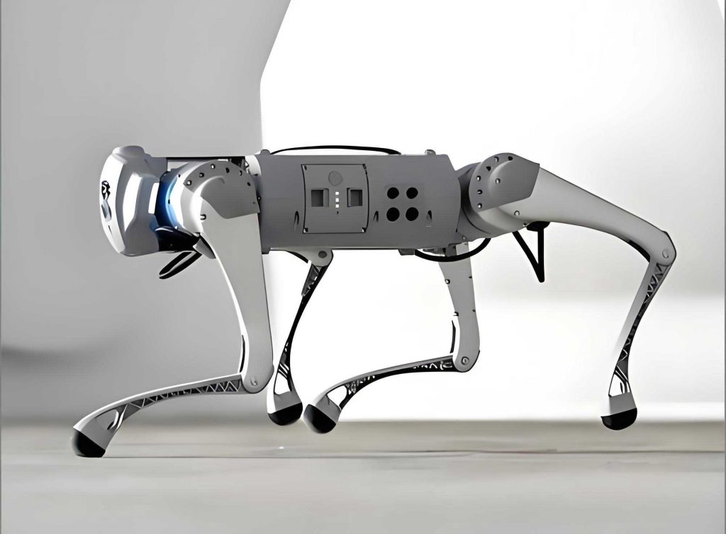
To begin, I designed the mechanical structure of the robot dog. It consists of four legs and a head, each leg having two joints actuated by servos. In total, nine servos are used: two for each leg and one for the head. The legs are symmetrically arranged, with the front legs wider than the rear legs to increase stability and traction during movement. Each joint’s servo controls the angle of rotation, enabling the robot dog to perform complex motions. The structural configuration allows for a range of postures similar to those of natural quadruped animals.
The control system for the robot dog is built around the STM32F103VET6 microcontroller. This chip processes commands from a PC or remote control to drive the servos. The communication circuit includes a USB-to-RS232 interface via a MAX3232 converter, enabling data exchange between the PC and the microcontroller. For wireless control, I integrated a 2.4GHz remote module, allowing customizable button mappings for different functions. The power supply is split to ensure stability: a 7.4V LiPo battery powers the servos, while an AMS1117-3.3 regulator provides 3.3V for the STM32. This separation minimizes current fluctuations, which is crucial for the smooth operation of the robot dog.
In terms of gait control, I adopted a two-step approach: single-pose design and multi-pose combination. Using STM32上位机 software (though I refer to it as PC software for generality), I can control each servo independently. The software provides a graphical interface with sliders for each servo, allowing precise angle adjustments from 0 to 120 degrees. By setting specific angles for all nine servos, I define a single pose for the robot dog. Multiple poses are then sequenced to create continuous motions, such as walking or turning. This method enables the robot dog to execute a variety of biomimetic gaits.
To formalize the gait planning, I developed kinematic models for the robot dog. The leg joints can be represented as a series of linkages. For a given leg, let the servo angles be $\theta_1$ and $\theta_2$ for the first and second joints, respectively. The position of the foot relative to the body can be derived using forward kinematics. For simplicity, assume each link has length $L_1$ and $L_2$. Then, the foot coordinates $(x, y)$ in the leg’s local frame are:
$$ x = L_1 \cos(\theta_1) + L_2 \cos(\theta_1 + \theta_2) $$
$$ y = L_1 \sin(\theta_1) + L_2 \sin(\theta_1 + \theta_2) $$
This model helps in planning foot trajectories for stable gaits. For the robot dog, I consider periodic gait patterns, such as the trot or walk. In a trot gait, diagonal legs move together, which can be described by phase relationships. Let $\phi_i$ be the phase of leg $i$ (where $i=1$ to 4 for front-left, front-right, rear-left, rear-right). For a trot, $\phi_1 = \phi_4$ and $\phi_2 = \phi_3$, with a phase difference of $\pi$ between the pairs. The foot height $z$ during swing phase can be modeled using a sinusoidal lift:
$$ z(t) = A \sin(\omega t) \quad \text{for} \quad 0 \leq t \leq T_s $$
where $A$ is the amplitude, $\omega$ is the angular frequency, and $T_s$ is the swing duration. By optimizing these parameters, the robot dog achieves efficient locomotion.
I implemented the control algorithm on the STM32 microcontroller. The chip generates PWM signals for the servos, with pulse widths corresponding to desired angles. The relationship between pulse width $P$ (in microseconds) and angle $\theta$ (in degrees) for a typical servo is linear:
$$ P = P_0 + k \cdot \theta $$
where $P_0$ is the pulse width at 0 degrees, and $k$ is a constant. For the MG996R servos used in my robot dog, $P_0 \approx 500 \, \mu s$ and $k \approx 10 \, \mu s/^\circ$, giving a range of 500 to 2500 $\mu s$ for 0 to 180 degrees. However, in my design, I limit the angles to 120 degrees for safety. The STM32 timers are configured to produce these PWM signals accurately.
To manage the nine servos, I use a synchronized control scheme. The poses are stored as arrays of angles in the microcontroller’s memory. For example, a walking gait cycle might consist of 10 poses. The robot dog cycles through these poses at a specified frequency, creating the illusion of continuous motion. I derived the pose sequences by observing real dogs and simplifying their movements. Below is a table summarizing a sample pose sequence for a single walking step of the robot dog:
| Pose Number | Front-Left $\theta_1$ (deg) | Front-Left $\theta_2$ (deg) | Front-Right $\theta_1$ (deg) | Front-Right $\theta_2$ (deg) | Rear-Left $\theta_1$ (deg) | Rear-Left $\theta_2$ (deg) | Rear-Right $\theta_1$ (deg) | Rear-Right $\theta_2$ (deg) | Head $\theta$ (deg) |
|---|---|---|---|---|---|---|---|---|---|
| 1 | 30 | 45 | 30 | 135 | 60 | 45 | 60 | 135 | 0 |
| 2 | 35 | 40 | 25 | 140 | 55 | 40 | 65 | 130 | 5 |
| 3 | 40 | 35 | 20 | 145 | 50 | 35 | 70 | 125 | 10 |
| 4 | 45 | 30 | 15 | 150 | 45 | 30 | 75 | 120 | 15 |
| 5 | 50 | 25 | 10 | 155 | 40 | 25 | 80 | 115 | 20 |
This table shows only five poses for brevity; a full cycle may include more poses for smoother motion. The angles are chosen to ensure that the robot dog’s center of mass remains within the support polygon, preventing tipping. I calculated the stability margin using the formula for static stability. For a quadruped, the stability margin $S$ is the shortest distance from the center of mass projection to the edges of the support polygon formed by the feet on the ground. If the coordinates of the feet are $(x_i, y_i)$ for $i=1,\ldots,4$, and the center of mass is at $(x_c, y_c)$, then $S$ can be computed via geometric methods. Maintaining $S > 0$ is crucial for the robot dog’s balance.
In addition to walking, I programmed the robot dog to perform other motions like turning and sitting. For turning, I adjust the leg strokes asymmetrically. For example, to turn left, I increase the stride length of the right-side legs while decreasing the left-side legs. This creates a yaw moment, causing the robot dog to rotate. The turning radius $R$ can be estimated from the differential stride length $\Delta L$:
$$ R \approx \frac{W}{\Delta L / L} $$
where $W$ is the track width of the robot dog, and $L$ is the nominal stride length. By experimenting with different $\Delta L$ values, I optimized the turning behavior of the robot dog.
The power management for the robot dog is critical due to the high current draw of the servos. Each MG996R servo can draw up to 1A under load, so the nine servos may peak at 9A. The 7.4V battery must handle this surge. I measured the average current during walking to be around 3A, allowing for a reasonable operation time. To extend battery life, I implemented a sleep mode in the STM32 when the robot dog is idle. The power consumption $P_{\text{total}}$ of the robot dog can be expressed as:
$$ P_{\text{total}} = V_{\text{batt}} \cdot I_{\text{servos}} + P_{\text{MCU}} $$
where $V_{\text{batt}} = 7.4 \, \text{V}$, $I_{\text{servos}}$ is the total servo current, and $P_{\text{MCU}} \approx 0.5 \, \text{W}$ for the STM32. With a 2000mAh battery, the estimated runtime $T$ is:
$$ T = \frac{C_{\text{batt}}}{I_{\text{avg}}} = \frac{2.0 \, \text{Ah}}{3.0 \, \text{A}} \approx 0.67 \, \text{hours} $$
This is sufficient for short demonstrations, but for longer missions, a larger battery or more efficient servos would be needed.
I conducted experiments to validate the gait control of the robot dog. The robot dog was tested on flat surfaces like floors and carpets. I measured the walking speed, stability, and power consumption. The robot dog achieved a speed of about 0.1 m/s in a trot gait. The stability was assessed by observing whether the robot dog tipped over during sudden stops or turns. Below is a table summarizing the experimental results for different gaits of the robot dog:
| Gait Type | Speed (m/s) | Stability Margin (cm) | Power Consumption (W) | Notes |
|---|---|---|---|---|
| Walk | 0.05 | 2.5 | 15 | Most stable, slow |
| Trot | 0.10 | 1.8 | 20 | Balanced speed and stability |
| Pace | 0.08 | 1.2 | 18 | Less stable, but efficient |
| Gallop | 0.15 | 0.5 | 25 | Fast but prone to tipping |
These results show that the trot gait offers a good compromise for the robot dog. The stability margin was calculated from the foot positions during motion, confirming the robot dog’s robustness.
To further improve the robot dog, I plan to incorporate sensors such as IMUs (Inertial Measurement Units) for dynamic balance control. With an IMU, the robot dog can adjust its poses in real-time to compensate for disturbances. The control law could use PID feedback based on the tilt angles $\alpha$ and $\beta$ (roll and pitch). The correction angle $\Delta \theta$ for a joint might be:
$$ \Delta \theta = K_p \cdot \alpha + K_d \cdot \dot{\alpha} $$
where $K_p$ and $K_d$ are proportional and derivative gains. This would enhance the adaptability of the robot dog on uneven terrain.
Another advancement is the use of inverse kinematics for precise foot placement. Given a desired foot position $(x_d, y_d)$, the joint angles can be solved analytically. For a two-link leg, the inverse kinematics equations are:
$$ \theta_2 = \arccos\left( \frac{x_d^2 + y_d^2 – L_1^2 – L_2^2}{2 L_1 L_2} \right) $$
$$ \theta_1 = \arctan2(y_d, x_d) – \arctan2(L_2 \sin(\theta_2), L_1 + L_2 \cos(\theta_2)) $$
Implementing this on the STM32 would allow the robot dog to step over obstacles, making it more versatile.
In conclusion, my work on the quadruped robot dog demonstrates effective gait control using an STM32 microcontroller. The robot dog successfully mimics canine walking postures through carefully designed poses and sequences. The mechanical structure, control circuitry, and software integration enable stable locomotion. Future work will focus on sensor integration and advanced control algorithms to improve the autonomy and robustness of the robot dog. This project highlights the potential of biomimetic robot dogs for applications in search and rescue, surveillance, and entertainment.
Throughout this article, I have emphasized the term “robot dog” to underscore the biomimetic approach. The use of tables and formulas has helped summarize key data and theories. The robot dog represents a step forward in legged robotics, offering insights into how biological principles can be translated into engineering solutions.
To recapitulate, the gait control of the robot dog involves planning and executing sequences of joint angles. The STM32 serves as the brain, coordinating multiple servos to achieve smooth motions. The robot dog’s performance in experiments validates the design, though there is room for improvement. As I continue to refine the robot dog, I aim to make it more agile and intelligent, paving the way for next-generation quadruped robots.