
As a researcher in mechanical dynamics, I have long been fascinated by the precision transmission systems used in robotics and high-end automation. The rotary vector reducer, a core component in such applications, exemplifies engineering excellence with its compact two-stage design. My focus has been on understanding how the inherent flexibility within its structure—specifically at support bearings and gear meshes—propagates into dynamic transmission error, ultimately affecting the positional accuracy of robotic arms. This article presents my analytical journey, employing a multi-degree-of-freedom dynamic model to dissect these effects. I will quantify the contributions of various elastic deformations and perform a detailed sensitivity analysis, providing a roadmap for optimizing the design of these critical reducers. The complexity of the rotary vector reducer lies in its synthesis of a primary involute planetary stage and a secondary cycloidal pin-wheel stage, all contributing to its high reduction ratio and renowned torsional stiffness.
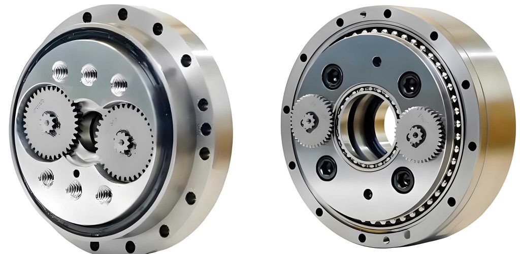
To model the dynamic behavior of a rotary vector reducer accurately, one must move beyond rigid-body assumptions. The elastic deflections at bearing supports and gear contacts are not merely secondary effects; they are primary sources of positional deviation at the output. In my work, I consider a specific model, analogous to the BX40E reducer. The primary stage consists of a sun gear, two planet gears, and a ring gear (often fixed), while the secondary stage comprises two cycloidal gears meshing with a ring of pins. The output is taken from the planetary carrier. The fundamental parameters for the gear system are summarized in the table below.
| Gear Type | Number of Teeth | Module (mm) | Pressure Angle (°) | Face Width (mm) | Pin Center Radius (mm) | Pin Radius (mm) |
|---|---|---|---|---|---|---|
| Sun Gear | 16 | 1.5 | 20 | 9 | – | – |
| Planet Gear | 32 | 1.5 | 20 | 9 | – | – |
| Cycloidal Gear | 39 | – | – | 12.5 | 69.5 | – |
| Pin | 40 | – | – | – | 69.5 | 3 |
The core of my analysis is a translational-torsional coupled linear dynamic model. Each component—sun gear, planet gears, cycloidal gears, and the carrier—is assigned degrees of freedom (DOF) for translation and rotation. The unique kinematics of the rotary vector reducer, where the cycloidal gears undergo eccentric motion, requires careful coordinate definition. A global coordinate system is fixed at the center of the pin ring. Local moving coordinates are attached to each cycloidal gear’s theoretical mass center, with one axis aligned along the eccentric direction.
The flexibility is introduced through stiffness matrices. Support stiffness values (e.g., at sun gear shaft, planet gear shafts, crank shaft-to-carrier interfaces, and cycloidal gear-to-crank interfaces) are calculated using Palmgren’s formula for rolling bearings. For a line contact, the stiffness $$k_b$$ is given by:
$$ k_b = \frac{l^{0.8}F^{0.1}}{1.36(h_1 + h_2)^{0.9}} $$
where $$l$$ is the effective contact length, $$F$$ is the load, and $$h_i$$ is a material parameter for body $$i$$ defined as:
$$ h_i = \frac{1 – \nu_i^2}{\pi E_i} $$
Here, $$E_i$$ and $$\nu_i$$ are the elastic modulus and Poisson’s ratio, respectively.
Gear mesh stiffness is modeled using Hertzian contact theory. The contact force $$F_k$$ between two teeth is represented as a spring-damper system in the direction normal to the contact surface:
$$ F_k = K \delta^n + D(\dot{\delta}) $$
For linearized dynamic analysis, the dominant term is the linear stiffness component. The Hertzian contact stiffness $$K$$ for two cylinders in contact is:
$$ K = \frac{4}{3\pi(h_1 + h_2)} \sqrt{\frac{r_1 r_2}{r_1 + r_2}} $$
where $$r_1$$ and $$r_2$$ are the radii of curvature at the contact point. For the involute gear pair, these are the base circle radii. For the cycloid-pin contact, the varying radius of curvature of the cycloidal tooth profile is considered, leading to a time-varying mesh stiffness $$k_{rcj}(t)$$. However, for the initial linear analysis presented here, an average stiffness value is often used. The overall stiffness matrix for the system, $$\mathbf{K}$$, is the sum of the support stiffness matrix $$\mathbf{K}_b$$ and the mesh stiffness matrix $$\mathbf{K}_m$$.
The equations of motion are derived using Newton’s second law. For a system with $$n$$ degrees of freedom, the matrix form is:
$$ \mathbf{M}\ddot{\mathbf{X}} + \mathbf{C}\dot{\mathbf{X}} + (\mathbf{K}_b + \mathbf{K}_m)\mathbf{X} = \mathbf{T} $$
Here, $$\mathbf{M}$$ is the mass matrix, $$\mathbf{C}$$ is the damping matrix (assumed proportional for simplicity), $$\mathbf{X}$$ is the displacement vector containing all translational and rotational DOFs, and $$\mathbf{T}$$ is the load torque vector. The displacement vector for the rotary vector reducer model is:
$$ \mathbf{X} = [x_s, y_s, \theta_s; x_{p_i}, y_{p_i}, \theta_{p_i}; \eta_{c_j}, \theta_{c_j}, \theta_{O_j}; x_{ca}, y_{ca}, \theta_{ca}]^T $$
where indices $$i=1,2$$ and $$j=1,2$$ denote the two planet gears and two cycloidal gears, respectively. The terms $$\eta_{c_j}$$ represent the radial deflection of the cycloidal gear in its local eccentric direction.
Solving these equations in the time or frequency domain yields the dynamic response. The key output metric is the Dynamic Transmission Error (DTE), defined as the difference between the actual output rotation and the ideal, rigid-body output rotation:
$$ \theta_{err}(t) = \theta_{out}(t) – \frac{\theta_{in}(t)}{i} $$
where $$i$$ is the ideal reduction ratio of the rotary vector reducer. A larger magnitude of $$\theta_{err}(t)$$ indicates poorer transmission accuracy.
My investigation first established a baseline under a load of 400 Nm and an input speed of 300 RPM. The dynamic mesh forces for both stages exhibit clear periodicity. For the primary stage, the force fluctuates with a period corresponding to the gear mesh frequency $$f_{m1}$$. The time-domain signal shows a mean force of approximately 222 N with superimposed variations due to single/double tooth pair contact. The Fast Fourier Transform (FFT) reveals dominant spectral peaks at $$f_{m1}$$ and its harmonics. The behavior of the secondary stage in a rotary vector reducer is more complex. Due to multi-tooth contact of the cycloidal gear, the dynamic mesh force has a much higher mean value (around 4050 N) but smaller relative fluctuations. Its spectrum contains the secondary mesh frequency $$f_{m2}$$ and its harmonics, but also shows influence from the primary stage frequencies due to the coupled dynamics.
The calculated DTE for this baseline case has a mean value of approximately 0.65 arc-minutes with a fluctuating amplitude of about 0.012 arc-minutes. The output speed, while having a steady mean, exhibits small oscillations. The frequency spectrum of both DTE and output speed is rich, containing components from both transmission stages, confirming the model captures the coupled dynamics of the rotary vector reducer.
To understand the influence of operating conditions, I varied the load torque and input speed independently. The results are synthesized in the table below, which shows the trend of key dynamic metrics.
| Operating Parameter | Primary Stage Mesh Force Amplitude | Secondary Stage Mesh Force Amplitude | Mean DTE (arc-min) | Output Speed Fluctuation Amplitude |
|---|---|---|---|---|
| Increasing Load (Constant Speed) | Increases | Increases slightly | Increases | Increases |
| Increasing Speed (Constant Load) | Increases | Nearly Constant | Nearly Constant | Increases |
The most significant finding is that DTE is strongly dependent on load. As load increases, the elastic deformations at all flexible interfaces (supports and contacts) increase, leading directly to a larger mean DTE. This trend is consistently observed in rotary vector reducers. Interestingly, while input speed increases dynamic excitation and amplifies force oscillations, its effect on the mean DTE value is minimal. However, higher speeds degrade the smoothness of operation, as evidenced by the increased amplitude of output speed fluctuations.
A deeper question is: which flexible factors contribute most to the overall DTE? To answer this, I decomposed the total output angular error $$\theta_{err}$$ into components attributable to specific sources: $$\theta_{e1}$$ from primary gear contact deformation, $$\theta_{e2}$$ from secondary gear contact deformation, and $$\theta_{eflex}$$ from the combined elastic deformation of all support bearings. The contribution ratios are defined as:
$$ C_I = \frac{\theta_{e1}}{\theta_{err}} \times 100\%,\quad C_{II} = \frac{\theta_{e2}}{\theta_{err}} \times 100\%,\quad C_{flex} = \frac{\theta_{eflex}}{\theta_{err}} \times 100\% $$
Under varying load, the contribution ratios exhibit clear trends, as summarized below:
| Load Condition | $$C_I$$ (Primary Contact) | $$C_{II}$$ (Secondary Contact) | $$C_{flex}$$ (Support Flexibility) |
|---|---|---|---|
| Low Load | < 5% | > 60% | ~30-33% |
| High Load | < 5% | > 60% | ~33-35% |
The results are striking. The contact deformation in the secondary cycloidal-pin stage is the dominant contributor, accounting for over 60% of the total DTE. This is logical because this stage carries the highest loads and its rotational output is directly coupled to the final output. The combined flexibility of all support bearings contributes about one-third of the error, a significant portion that cannot be ignored. The contribution of the primary involute stage contact is negligible (less than 5%). This is because its mesh forces are lower, and any angular error it generates is reduced by the primary stage gear ratio before being transmitted to the output. This hierarchy of contributions is a critical insight for designers of rotary vector reducers.
To provide actionable design guidance, a sensitivity analysis was performed. I employed the finite difference method to calculate the local sensitivity $$S_{E_i}$$ of the mean DTE to each stiffness parameter $$k_i$$:
$$ S_{E_i} = \frac{\partial e}{\partial k_i} \approx \frac{e(k_i) – e(k_i – \Delta k_i)}{\Delta k_i} $$
where $$e(k_i)$$ is the mean DTE value when the stiffness is at its nominal value. The calculated sensitivities for key stiffness parameters in the rotary vector reducer are listed below.
| Flexibility Location | Stiffness Parameter | Nominal Stiffness (N/m) | Sensitivity $$S_{E_i}$$ |
|---|---|---|---|
| Support Locations | Sun Gear Shaft ($$k_s$$) | 4.28e6 | 0.0001 |
| Planet Gear Shafts, combined ($$k_p$$) | 1.52e8 | 0.0003 | |
| Cycloid Gear – Crank, combined ($$k_{pc}$$) | 1.01e9 | 0.0542 | |
| Carrier – Crank Shaft, combined ($$k_b$$) | 9.89e8 | 0.0362 | |
| Main Bearing (Carrier) ($$k_{ca}$$) | 2.42e8 | 0.0001 | |
| Contact Locations | Involute Gear Mesh ($$k_{spi}$$) | 7.55e8 | 0.0062 |
| Cycloid-Pin Mesh ($$k_{rcj}$$) | 9.50e8 | 0.1446 |
The sensitivity analysis yields crucial quantitative insights. Concerning support flexibility, the DTE of the rotary vector reducer is most sensitive to the stiffness at the “cycloid gear – crank” and the “carrier – crank shaft” interfaces. Improving the bearing design or fit at these locations will have the most significant impact on reducing transmission error. In contrast, DTE is virtually insensitive to the stiffness of the sun gear shaft or the main carrier support bearing within the analyzed model. For gear contact stiffness, the sensitivity is an order of magnitude higher for the secondary cycloidal-pin mesh than for the primary involute mesh. This unequivocally points to the secondary stage contact characteristics as the most critical factor for the transmission accuracy of a rotary vector reducer. Any design effort aimed at optimizing tooth profile, material, or heat treatment for the cycloidal gear and pins will pay the highest dividends in precision.
In conclusion, my dynamic modeling and analysis of the rotary vector reducer have clarified the profound impact of flexible factors on its transmission accuracy. The dynamic transmission error increases substantially with load, while increased input speed primarily affects operational smoothness. The decomposition of error sources reveals that elastic deformation in the secondary cycloidal-pin transmission stage is the predominant contributor, followed by the combined deformation of support bearings. The sensitivity analysis provides a clear priority list: to enhance the precision of a rotary vector reducer, designers should first focus on maximizing the contact stiffness of the cycloid-pin mesh and the support stiffness at the crank-cycloid and crank-carrier interfaces. These findings, grounded in a multi-DOF dynamic model incorporating Hertzian contact and Palmgren-based support stiffness, offer a validated framework for the systematic design and optimization of these sophisticated precision reducers, ensuring they meet the ever-increasing demands of robotic and automated systems.