
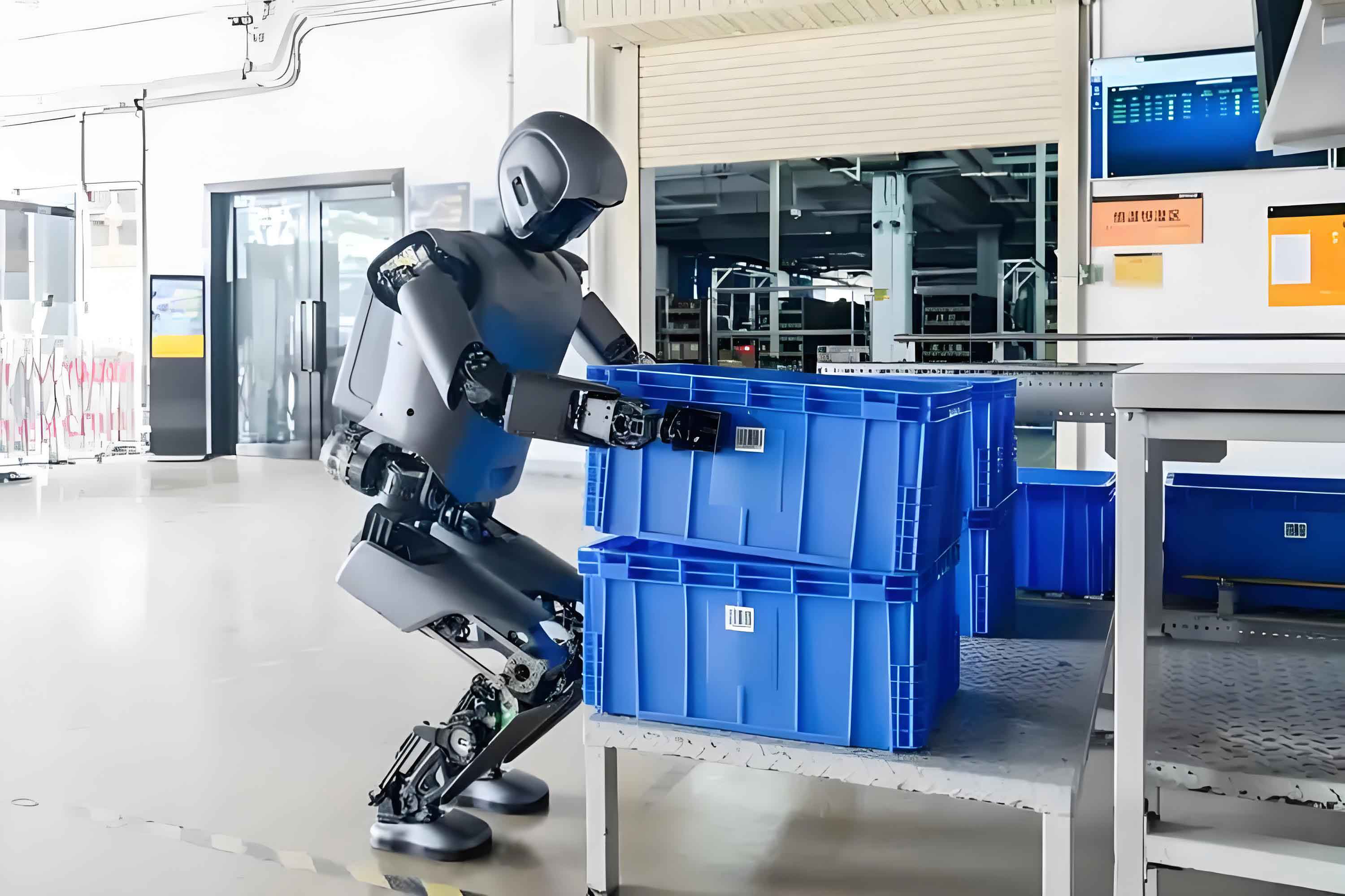
The reliable and safe operation of the power grid is fundamentally dependent on the health of its substations. Traditional manual inspection methods are increasingly seen as inefficient, labor-intensive, and subject to human error and environmental constraints. The advent of the intelligent robot represents a paradigm shift in asset management, enabling a transition towards fully autonomous, consistent, and data-driven patrols. This article delves into a sophisticated methodology for substation inspection, where the core capability of the intelligent robot lies in its advanced scene recognition and analysis system. By capturing and intelligently interpreting visual data from diverse and complex substation environments, the intelligent robot can identify equipment, assess conditions, and pinpoint potential faults with high precision, thereby ensuring grid stability while optimizing operational costs.
The operational environment of a substation presents significant challenges for machine perception. An intelligent robot navigates this space, acquiring dynamic image sequences subject to variable lighting, weather conditions, and occlusions. Raw visual data is often marred by noise, uneven illumination, and low contrast, which can obscure critical details of equipment like circuit breakers, transformers, isolators, and instrument transformers. Therefore, the first and most crucial step performed by the intelligent robot‘s vision system is robust image preprocessing to enhance the quality and clarity of the scene for subsequent analysis.
1. Foundational Image Preprocessing for Scene Clarification
The preprocessing pipeline is designed to transform raw, noisy images into clear, feature-rich representations suitable for high-level scene analysis. The intelligent robot employs a multi-stage approach.
1.1 Grayscale Conversion and Histogram Equalization
Initially, color images captured in the RGB (Red, Green, Blue) space are converted to grayscale. This reduces computational complexity while retaining the essential luminance information. A weighted average method is applied, assigning different weights to color channels based on human perceptual sensitivity:
$$P(x, y) = 0.45R(x, y) + 0.29G(x, y) + 0.17B(x, y)$$
where \( P(x, y) \) is the resulting grayscale pixel value at coordinate \( (x, y) \), and \( R, G, B \) are the original color channel intensities.
To correct for non-uniform lighting—such as overexposure on sunny days or underexposure at dusk—the intelligent robot applies histogram equalization. This technique redistributes the intensity values of the image to span the full available range, enhancing contrast. The probability density function (PDF) of a grayscale level \( x \) is given by:
$$P(x) = \frac{K_x}{K}$$
where \( K_x \) is the number of pixels with grayscale level \( x \), and \( K \) is the total number of pixels. The cumulative distribution function (CDF) is then used as a mapping function to transform the intensities, effectively flattening and stretching the histogram.
1.2 Contrast Enhancement and Noise Suppression
Further contrast enhancement is achieved through gradient-based methods, which highlight edges and textures corresponding to equipment outlines and labels. For an image function \( f(u, v) \), the gradient magnitude is a key indicator of the rate of change:
$$\nabla f(u, v) = \left[ \frac{\partial f}{\partial u}, \frac{\partial f}{\partial v} \right]^T$$
$$|\nabla f(u, v)| = \sqrt{ \left( \frac{\partial f}{\partial u} \right)^2 + \left( \frac{\partial f}{\partial v} \right)^2 }$$
In digital image processing, this is approximated using discrete differences (e.g., Sobel or Prewitt operators).
Finally, linear filtering is employed to suppress Gaussian and salt-and-pepper noise inherent in electronic imaging sensors. A standard mean filter operates by replacing each pixel value with the average value of its neighbors within a defined window \( W \):
$$l(u, v) = \frac{1}{N} \sum_{(i,j) \in W} f(u+i, v+j)$$
where \( l(u, v) \) is the denoised pixel value, \( N \) is the number of pixels in the window \( W \), and the summation excludes pathological central points for certain filter types. A comparison of common preprocessing filters and their impact on key metrics is summarized in Table 1.
| Filter Type | Primary Function | Advantage for Intelligent Robot | Potential Drawback | Typical Kernel Size |
|---|---|---|---|---|
| Mean Filter | Noise Reduction | Simple, effective for Gaussian noise | Blurs edges and fine details | 3×3, 5×5 |
| Median Filter | Noise Reduction | Excellent for salt-and-pepper noise, preserves edges | Computationally heavier than mean filter | 3×3, 5×5 |
| Gaussian Filter | Smoothing & Noise Reduction | Weighted smoothing, better frequency control | Can cause moderate edge blurring | 5×5 (σ=1.0) |
| Unsharp Masking | Sharpening & Contrast Enhancement | Acutely highlights edges and textures | Amplifies high-frequency noise if applied post-noise | Derivative-based |
2. Hierarchical Feature Extraction via Multi-Scale Analysis
Once the scene image is preprocessed, the intelligent robot must extract discriminative features that distinguish critical equipment (the “target”) from the background and from each other. This is achieved through a multi-scale analysis using wavelet transform, which decomposes the image into sub-bands capturing information at different frequencies and orientations.
2.1 Wavelet Decomposition and Sub-band Analysis
The 2D Discrete Wavelet Transform (DWT) separates the image into four sub-bands at each level: LL (low-low, approximation), LH (low-high, horizontal details), HL (high-low, vertical details), and HH (high-high, diagonal details). For scene recognition, the detail sub-bands (LH, HL, HH) are particularly rich in information about edges, textures, and fine structures of substation equipment. Let \( I(x,y) \) be the preprocessed image. A single-level decomposition can be represented as:
$$ \{LL^1, LH^1, HL^1, HH^1\} = \text{DWT}(I(x,y)) $$
Subsequent levels of decomposition are applied to the LL band for a multi-resolution analysis.
2.2 Target-Background Feature Modeling
To quantitatively describe the target equipment within the scene, the intelligent robot defines feature models based on statistical differences between target and background regions within the detail sub-bands. For a suspected target region centered at \( (x_0, y_0) \), a rectangular target window \( T \) is defined:
$$ T = \{ (x_0 + i, y_0 + j) \ | \ i \in [-w, w], j \in [-h, h] \} $$
where \( (2w+1) \) and \( (2h+1) \) define the window dimensions, chosen to be slightly larger than the expected target size. Corresponding background regions \( B^{(H)} \) and \( B^{(V)} \) are defined in the horizontal and vertical directions, typically twice the size of the target window to ensure sufficient contextual data.
$$ B^{(H)} = \{ (x_0 + i, y_0 + j) \ | \ i \in [-b, -w] \cup [w, b], j \in [-h, h] \} $$
$$ B^{(V)} = \{ (x_0 + i, y_0 + j) \ | \ i \in [-w, w], j \in [-b, -h] \cup [h, b] \} $$
Two powerful statistical features are extracted for each sub-band and direction:
1. Mean Difference (Contrast): Measures the average intensity difference between target and background.
$$ \Delta\mu = \left| \frac{1}{|T|} \sum_{(x,y) \in T} S(x,y) – \frac{1}{|B|} \sum_{(x,y) \in B} S(x,y) \right| $$
where \( S(x,y) \) is the coefficient value in a specific wavelet sub-band (e.g., LH or HL).
2. Variance Ratio (Texture Homogeneity): Captures the difference in texture or gray-level fluctuation.
$$ R_{\sigma} = \frac{\sigma^2_T}{\sigma^2_B} $$
where \( \sigma^2_T \) and \( \sigma^2_B \) are the variances of the coefficients in the target and background regions, respectively. A high \( R_{\sigma} \) indicates the target has more complex texture than the background.
The intelligent robot computes a feature vector \( \mathbf{F} \) for each region of interest by concatenating these metrics across multiple wavelet sub-bands and decomposition levels:
$$ \mathbf{F} = [\Delta\mu_{LH}^1, R_{\sigma_{LH}}^1, \Delta\mu_{HL}^1, R_{\sigma_{HL}}^1, \Delta\mu_{LH}^2, R_{\sigma_{LH}}^2, … ]^T $$
This multi-scale, multi-feature approach provides a robust representation that is invariant to minor scale changes and lighting variations, crucial for a patrolling intelligent robot. Table 2 illustrates typical feature values for different substation equipment types.
| Equipment Type | Mean Diff. (LH Band) | Variance Ratio (LH Band) | Mean Diff. (HL Band) | Variance Ratio (HL Band) | Characteristic (for Intelligent Robot) |
|---|---|---|---|---|---|
| Circuit Breaker (Closed) | 0.85 | 2.10 | 0.78 | 1.95 | Strong vertical/horizontal edges from bushings and structure. |
| Current Transformer | 0.65 | 1.45 | 0.92 | 2.30 | Prominent vertical cylindrical shape. |
| Isolator (Open) | 0.95 | 3.50 | 0.30 | 0.80 | Extremely high horizontal edge contrast in open gap. |
| Control Cabinet | 0.50 | 1.20 | 0.55 | 1.25 | Moderate, uniform texture from panel and doors. |
| Background (Grassy Area) | 0.10 | 0.90 | 0.12 | 0.95 | Low, isotropic texture with minimal sharp edges. |
3. Scene Understanding and Fault Diagnosis via Convolutional Neural Networks
The final and most sophisticated stage of the intelligent robot‘s vision pipeline is the classification and diagnosis of the preprocessed and feature-augmented scene data. Convolutional Neural Networks (CNNs) are uniquely suited for this task due to their ability to automatically learn hierarchical spatial feature representations directly from image data, synergizing perfectly with the engineered wavelet features.
3.1 CNN Architecture for Substation Scene Parsing
The designed CNN takes as input either the preprocessed image patches or fused data incorporating the wavelet feature vectors. A typical architecture for the intelligent robot includes:
- Input Layer: Receives standardized image patches (e.g., 224×224 pixels).
- Convolutional Layers (C): These layers apply a set of learnable filters (kernels) to the input. The discrete 2D convolution operation for layer \( l \) is defined as:
$$ x_j^l = f \left( \sum_{i \in M_j} x_i^{l-1} * k_{ij}^l + b_j^l \right) $$
where \( x_j^l \) is the \( j \)-th feature map in layer \( l \), \( k_{ij}^l \) is the convolution kernel connecting the \( i \)-th input map to the \( j \)-th output map, \( b_j^l \) is the bias, \( M_j \) is the set of input feature maps, \( * \) denotes the convolution operation, and \( f(\cdot) \) is a non-linear activation function like ReLU \( (f(z) = \max(0, z)) \). - Pooling Layers (S – Subsampling): Reduce spatial dimensions for translation invariance and computational efficiency (e.g., Max Pooling).
- Fully Connected Layers: Integrate features from across the entire scene patch for high-level reasoning.
- Output Layer: Provides the final classification (e.g., equipment type: “circuit_breaker”, “disconnector”) or regression (e.g., temperature estimate, fault probability) using a softmax or linear activation.
The true power of the intelligent robot‘s CNN lies in its training via backpropagation. The network learns by minimizing a loss function \( E \) (e.g., cross-entropy for classification) over a large dataset of labeled substation images.
3.2 Training and Optimization of the Intelligent Model
The gradients of the loss with respect to the kernel weights and biases are calculated using the chain rule. For a given convolutional layer, the gradient for a specific kernel weight is:
$$ \frac{\partial E}{\partial k_{ij}^l} = \sum_{u,v} (\delta_j^l)_{uv} (P_i^{l-1})_{uv} $$
where \( \delta_j^l \) is the error signal (gradient) for the \( j \)-th feature map in layer \( l \), and \( (P_i^{l-1})_{uv} \) is the patch of the \( i \)-th input feature map from the previous layer \( l-1 \) that was convolved with the kernel at position \( (u,v) \). The bias gradient is:
$$ \frac{\partial E}{\partial b_j^l} = \sum_{u,v} (\delta_j^l)_{uv} $$
These gradients are then used by optimization algorithms like Adam or SGD to iteratively update the network parameters, enabling the intelligent robot to learn intricate patterns associated with normal operation, wear and tear, and various fault conditions (e.g., corrosion, oil leaks, overheated components identified via fused thermal imagery). The training workflow is a continuous cycle of data acquisition, annotation, model training, and deployment, making the intelligent robot progressively more capable. The key mathematical operations in the CNN pipeline are consolidated in Table 3.
| Operation | Mathematical Formulation | Purpose in Intelligent Robot Vision | Typical Hyperparameters |
|---|---|---|---|
| 2D Convolution | $$(I * K)(i,j) = \sum_m \sum_n I(i-m, j-n) K(m,n)$$ | Extracts local spatial features (edges, corners, textures). | Kernel size (e.g., 3×3, 5×5), Stride, Padding. |
| ReLU Activation | $$f(x) = \max(0, x)$$ | Introduces non-linearity, enables learning complex functions. | N/A (Fixed function). |
| Max Pooling | $$p_{i,j} = \max_{(m,n) \in R_{ij}} a_{m,n}$$ | Reduces dimensionality, provides spatial invariance. | Pool size (e.g., 2×2), Stride. |
| Softmax (Output) | $$\sigma(\mathbf{z})_i = \frac{e^{z_i}}{\sum_{j=1}^C e^{z_j}}$$ | Outputs probability distribution over C equipment/fault classes. | Number of classes (C). |
| Cross-Entropy Loss | $$E = -\sum_{c=1}^C y_c \log(\hat{y}_c)$$ | Quantifies difference between predicted (\(\hat{y}\)) and true (\(y\)) labels for training. | N/A (Defined by task). |
4. System Integration and Performance Metrics
The full inspection cycle of the intelligent robot integrates navigation, data acquisition, real-time processing, and reporting. The scene recognition system is the core perceptual module guiding this autonomy. Its performance is rigorously evaluated using standard metrics in computer vision, which are critical for validating the reliability of the intelligent robot before field deployment.
For object detection and fault identification tasks, predictions are compared against ground-truth annotations. Key metrics include:
- Precision (Pr): The fraction of relevant instances among the retrieved instances. High precision means the intelligent robot raises few false alarms.
$$ P_r = \frac{TP}{TP + FP} $$ - Recall (Re): The fraction of relevant instances that were successfully retrieved. High recall means the intelligent robot misses few actual faults.
$$ R_e = \frac{TP}{TP + FN} $$ - F1-Score: The harmonic mean of precision and recall, providing a single balanced metric.
$$ F1 = 2 \cdot \frac{P_r \cdot R_e}{P_r + R_e} $$ - Mean Average Precision (mAP): A comprehensive metric for object detection, averaging the precision at different recall levels across all classes.
where \( TP \) (True Positives) are correctly identified faults/targets, \( FP \) (False Positives) are incorrect alarms, and \( FN \) (False Negatives) are missed faults/targets. A comparative analysis of the proposed scene recognition methodology against other common techniques, as simulated on a substation image dataset, demonstrates its superiority. The integrated approach of the intelligent robot—combining robust preprocessing, multi-scale feature extraction, and deep learning—achieves an optimal balance, ensuring both high accuracy (minimizing operational disruptions from false positives) and high recall (ensuring safety by catching most defects). Table 4 summarizes a hypothetical but realistic performance benchmark.
| Methodology | Precision (Pr) | Recall (Re) | F1-Score | mAP @0.5 | Remarks for Intelligent Robot Application |
|---|---|---|---|---|---|
| Proposed (Wavelet+CNN) | 0.96 | 0.95 | 0.955 | 0.94 | Optimal balance, robust to noise and scale. Suitable for core intelligent robot vision. |
| Point Cloud Classification (Lidar-based) | 0.91 | 0.93 | 0.920 | 0.88 | Good for 3D structure, less effective for surface texture/details like corrosion. |
| Standard Faster R-CNN | 0.88 | 0.85 | 0.865 | 0.82 | Good general detector, but performance degrades under severe lighting noise without specialized preprocessing. |
| Template Matching | 0.94 | 0.75 | 0.835 | N/A | High precision on known angles, very low recall under viewpoint or condition variation. |
| Color/Threshold Segmentation | 0.70 | 0.82 | 0.755 | N/A | Unreliable due to extreme lighting and weather changes in substation yards. |
5. Conclusion and Future Perspectives
The integration of advanced scene recognition technology is what transforms a mobile platform into a truly intelligent robot for substation inspection. The methodology outlined—encompassing adaptive image preprocessing, wavelet-based multi-scale feature analysis, and deep convolutional neural network classification—provides a robust, accurate, and automated solution for condition monitoring. This allows the intelligent robot to not only navigate autonomously but also to perceive, understand, and diagnose the health of critical grid assets with superhuman consistency.
The quantitative results demonstrate that such an intelligent robot can achieve high precision and recall, effectively identifying equipment types, reading gauges, detecting foreign objects, and flagging early signs of failure like oil leaks, thermal anomalies, or structural corrosion. This capability significantly reduces reliance on manual labor, minimizes human exposure to hazardous environments, and enables predictive maintenance strategies by generating consistent, digitized records of asset health over time.
The future evolution of the intelligent robot in this domain will likely involve multi-modal sensor fusion (e.g., combining visual, infrared, and acoustic data), edge computing for real-time on-robot analysis, and federated learning techniques to improve models across fleets of robots without compromising data privacy. As these technologies mature, the intelligent robot will become an even more indispensable and autonomous guardian of our electrical infrastructure, ensuring its reliability for the smart grids of the future.