
The quest to develop robotic end-effectors that approach the dexterity and adaptability of the human hand remains a central challenge in robotics. While significant progress has been made, most existing dexterous robotic hand designs excel primarily at fundamental grasping and pinching tasks. True, high-fidelity manipulation—particularly the controlled rotation of objects within the grasp—is an area that warrants deeper investigation. This capability is crucial for complex assembly, tool use, and general-purpose manipulation in unstructured environments. This article presents a comprehensive kinematic analysis and simulation study of a novel dexterous robotic hand mechanism inspired by the cooperative motion of the human thumb and index finger. The design emphasizes not only stable grasping but also the active, in-hand rotation of objects.
Kinematic analysis forms the foundational step in understanding the relationship between joint actuator inputs and the resulting motion of the end-effector, which in this case are the fingertips. Various methods, such as the Denavit-Hartenberg (D-H) convention and the closed-loop vector method, are commonly employed. Previous studies have applied these techniques to analyze rehabilitation robots, grippers, and mechanisms driven by novel actuators like twisted-and-coiled polymers. Building upon this knowledge, this work employs a detailed closed-loop vector approach to derive the forward and inverse kinematics for a specific finger mechanism of the proposed dexterous robotic hand. Following the theoretical analysis, the operational workspace of the finger is determined through numerical methods. Finally, the article validates the design’s intended functionality through dynamic simulation in a three-dimensional software environment, demonstrating the hand’s ability to pinch and rotate an object, thereby confirming its enhanced dexterous robotic hand capabilities.
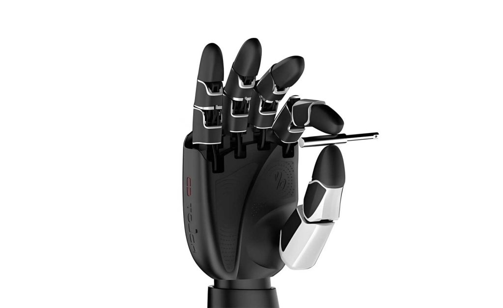
The proposed dexterous robotic hand features a relatively simple yet effective architecture. The entire system comprises two fingers and a palm base, resulting in a total of four degrees of freedom (DOF). Importantly, both the palm mechanism and each finger contribute to this mobility. This configuration offers dual advantages: it enhances the hand’s ability to conform to and securely grip objects of various shapes, and it provides the necessary articulation to impart rotational motion to a grasped object. The actuation is typically achieved using motors, with specific drivetrains (like flexible belts or tendons) connecting actuators to the finger joints. This distributed actuation scheme is key to achieving the independent control required for dexterous manipulation with this dexterous robotic hand.
The core of the dexterous robotic hand‘s functionality lies in its finger mechanism. To analyze its motion, we consider its state during a precision pinch grasp. In this mode, the proximal and distal phalanges are temporarily locked together via a torsional spring or similar mechanism, effectively forming a single rigid body with link L3. The simplified planar kinematic diagram for one finger in this configuration is established. A local coordinate frame \(O_1 – y_1z_1\) is defined at the base pivot \(O_1\). The lengths of the links are denoted as \(L_i\) (for i = 1, 2, …, 5, 7), and \(L_6\) represents the fixed distance between two key joint points. The angles \(\theta_i\) represent the orientation of link \(L_i\) relative to the positive \(y_1\)-axis. Key constant angles within the mechanism are \(\alpha_0\), \(\alpha_1\), and \(\alpha_2\). In this analysis, link \(L_1\) is designated as the input link, with \(\theta_1\) as the input angle. The output angles of interest are \(\theta_2\) and \(\theta_6\), which define the configuration of the finger and the locked phalange assembly.
The constant distance \(L_6\) is derived from the geometry of the locked phalange triangle using the Law of Cosines:
$$L_6 = \sqrt{L_3^2 + L_4^2 – 2 L_3 L_4 \cos(\alpha_0)}$$
For the forward kinematics problem, the goal is to find the output angles \((\theta_2, \theta_6)\) and key point coordinates given the input \(\theta_1\). Applying the closed-loop vector method to the kinematic chain \(O_1 \rightarrow I \rightarrow J \rightarrow W\) yields the vector loop equation:
$$\overrightarrow{O_1I} + \overrightarrow{IJ} = \overrightarrow{O_1W} + \overrightarrow{WJ}$$
Expressing this in complex exponential form (where \(e^{i\theta} = \cos\theta + i\sin\theta\)) provides a compact representation:
$$L_1 e^{i\theta_1} + L_2 e^{i\theta_2} = L_5 e^{i\theta_5} + L_6 e^{i\theta_6}$$
Separating the real and imaginary components gives the scalar equations:
$$
\begin{aligned}
L_1 \cos\theta_1 + L_2 \cos\theta_2 &= L_5 \cos\theta_5 + L_6 \cos\theta_6 \\
L_1 \sin\theta_1 + L_2 \sin\theta_2 &= L_5 \sin\theta_5 + L_6 \sin\theta_6
\end{aligned}
$$
In these equations, \(L_5\) and \(\theta_5\) are considered known design parameters. By manipulating these equations, we can eliminate one variable. Isolating terms with \(\theta_2\) leads to a standard form:
$$P_1 \sin\theta_2 + Q_1 \cos\theta_2 + R_1 = 0$$
where the coefficients are:
$$
\begin{aligned}
P_1 &= 2 L_2 (L_1 \sin\theta_1 – L_5 \sin\theta_5) \\
Q_1 &= 2 L_2 (L_1 \cos\theta_1 – L_5 \cos\theta_5) \\
R_1 &= (L_1 \cos\theta_1 – L_5 \cos\theta_5)^2 + (L_1 \sin\theta_1 – L_5 \sin\theta_5)^2 + L_2^2 – L_6^2
\end{aligned}
$$
This trigonometric equation can be solved using the tangent half-angle substitution, yielding an explicit expression for \(\theta_2\):
$$\theta_2 = 2 \arctan\left( \frac{P_1 + \sqrt{P_1^2 + Q_1^2 – R_1^2}}{Q_1 – R_1} \right)$$
Once \(\theta_2\) is known, \(\theta_6\) can be computed directly from the original scalar equations:
$$\theta_6 = \arctan\left( \frac{L_1 \sin\theta_1 + L_2 \sin\theta_2 – L_5 \sin\theta_5}{L_1 \cos\theta_1 + L_2 \cos\theta_2 – L_5 \cos\theta_5} \right)$$
Subsequently, the angle \(\theta_3\) for link \(L_3\) is found by applying the Law of Cosines to the triangle formed by links \(L_3\), \(L_7\), and the virtual link between joints J and K:
$$\theta_3 = \arccos\left( \frac{L_3^2 + L_7^2 – L_4^2}{2 L_3 L_7} \right) + \theta_7 – \pi$$
Finally, the coordinates of critical points I (actuator connection), J (first knuckle), K (second knuckle/phalange lock), and N (fingertip) are computed sequentially:
$$
\begin{aligned}
\text{Point I:} & \quad (y_I, z_I) = (L_1 \cos\theta_1, L_1 \sin\theta_1) \\
\text{Point J:} & \quad (y_J, z_J) = (L_1 \cos\theta_1 + L_2 \cos\theta_2, L_1 \sin\theta_1 + L_2 \sin\theta_2) \\
\text{Point K:} & \quad (y_K, z_K) = (y_J + L_3 \cos\theta_3, z_J + L_3 \sin\theta_3) \\
\text{Point N (Fingertip):} & \quad (y_N, z_N) = (y_K, z_K + L_7)
\end{aligned}
$$
For the inverse kinematics problem, the objective is to find the required input angle \(\theta_1\) that places the fingertip point N at a desired coordinate \((y_N, z_N)\). The process works backwards through the geometric chain. First, the coordinates of point K are immediately found since it shares the same y-coordinate as N:
$$(y_K, z_K) = (y_N, z_N – L_7)$$
Next, point J is determined based on the fixed geometric relationship between J, K, and the locked phalange angle \(\alpha_0\):
$$
\begin{aligned}
y_J &= y_N – L_3 \sin\alpha_0 \\
z_J &= z_N – L_7 – L_3 \cos\alpha_0
\end{aligned}
$$
With point J known, the constraint equation from link \(L_2\) is applied:
$$(y_J – L_1 \cos\theta_1)^2 + (z_J – L_1 \sin\theta_1)^2 = L_2^2$$
Using the tangent half-angle substitution \(\tan(\theta_1/2) = k_1\), this equation transforms into a quadratic in \(k_1\):
$$(c_1 + b_1) k_1^2 + 2 a_1 k_1 + (b_1 – c_1) = 0$$
where:
$$
\begin{aligned}
a_1 &= -2 L_1 z_J \\
b_1 &= -2 L_1 y_J \\
c_1 &= L_1^2 – L_2^2 + y_J^2 + z_J^2
\end{aligned}
$$
The solution for \(k_1\) is:
$$k_1 = \frac{-a_1 \pm \sqrt{a_1^2 + b_1^2 – c_1^2}}{c_1 – b_1}$$
Typically, only one solution is physically feasible given the mechanism’s constraints. The corresponding input angle is then:
$$\theta_1 = 2 \arctan\left( \frac{-a_1 + \sqrt{a_1^2 + b_1^2 – c_1^2}}{c_1 – b_1} \right)$$
The reachable workspace of the fingertip is a critical performance metric for any dexterous robotic hand. It defines the spatial volume within which the fingertip can be positioned. Using the forward kinematics equations and the specified link lengths (\(L_1=54\,mm, L_2=66\,mm, L_3=27\,mm, L_4=45\,mm, L_7=40\,mm\)), the workspace is generated by varying the input angle \(\theta_1\) over its permissible range and computing the resulting \((y_N, z_N)\) coordinates. A numerical sweep yields the workspace plot, which is often visualized as a dense point cloud or a boundary contour. For the given parameters, the workspace forms a continuous, crescent-shaped region without internal voids, indicating smooth and continuous motion capability. The numerical extents are summarized below:
| Axis | Minimum Reach (mm) | Maximum Reach (mm) | Total Span (mm) |
|---|---|---|---|
| y-axis (lateral) | -24 | 78 | 102 |
| z-axis (vertical) | 53 | 128 | 75 |
The dexterity of a robotic hand can be quantified through various indices, such as the volume of the workspace, the ability to apply forces in different directions, or the conditioning of the kinematic Jacobian matrix. For this dexterous robotic hand, a significant aspect of dexterity is its ability to reorient objects. This can be analyzed by considering the differential motion of the two fingertips during a coordinated manipulation task. If we denote the position of the left and right fingertips as \(\mathbf{p}_l\) and \(\mathbf{p}_r\), and their velocities as \(\dot{\mathbf{p}}_l\) and \(\dot{\mathbf{p}}_r\), the motion of the object’s center can be approximated, and more importantly, its rotational velocity \(\omega_{obj}\) is related to the relative tangential velocities of the fingertips. A simplified 2D model gives:
$$\omega_{obj} \approx \frac{(\dot{\mathbf{p}}_r – \dot{\mathbf{p}}_l) \cdot \hat{\mathbf{t}}}{2 R}$$
where \(R\) is the object’s radius and \(\hat{\mathbf{t}}\) is the unit tangent vector at the contact points. The Jacobian matrices \(\mathbf{J}_l(\mathbf{q})\) and \(\mathbf{J}_r(\mathbf{q})\) for each finger, which map joint velocities \(\dot{\mathbf{q}}\) to fingertip velocities, are central to this analysis. The overall dexterous robotic hand manipulability for rotation can be assessed by analyzing the combined kinematic structure that generates this relative motion.
To validate the practical functionality of the dexterous robotic hand, a dynamic simulation was conducted. A cylindrical object P with a diameter of 20 mm and a length of 130 mm was used as the target. The simulation modeled the complete sequence: from an open-hand posture, through finger closure to pinch the object, to the active rotation of the object within the grasp. The actuation of four motors (M1, M2, M3, M4) was defined using step functions to control their displacement over time. The simulation parameters are tabulated below:
| Actuator Joint | Driving Function (STEP(Time, t_start, x_start, t_end, x_end)) | Primary Function |
|---|---|---|
| Motor 1 | STEP(Time, 3, 0, 7, 2.5) | Drives palm/base motion for object rotation. |
| Motor 2 | STEP(Time, 0, 0, 3, 16) | Closes both fingers to pinch the object. |
| Motor 3 | STEP(Time, 3, 0, 7, 0.6) | Coordinates with M1 & M4 for rotational manipulation. |
| Motor 4 | STEP(Time, 3, 0, 7, 0.6) | Coordinates with M1 & M3 for rotational manipulation. |
The simulation proceeded in distinct phases. From t=0s to t=3s, Motor 2 was activated, causing both fingers to move symmetrically to contact and firmly pinch the cylindrical object. During this phase, Motors 1, 3, and 4 were stationary. From t=3s to t=7s, Motor 2 held its position to maintain grip, while Motors 1, 3, and 4 engaged in a coordinated manner. This combined action resulted in a relative motion between the palm and the fingers, causing the pinched object to rotate about its longitudinal axis. The motion trajectories clearly show an initial linear approach (pinch) followed by a curved path (rotation), visually confirming the successful execution of the planned manipulation sequence with the dexterous robotic hand.
The simulation outputs provide detailed kinematic data for the actuators. The displacement curves for Motors 1 and 2 show the expected step-like profiles: Motor 2 moves 16 units during the first 3 seconds, and Motor 1 moves 2.5 units during the subsequent 4 seconds. Their corresponding velocity plots show impulse-like spikes at the step transitions, which in a real system would be smoothed by control profiles. More insightful are the results for Motor 3 (and similarly Motor 4), which is directly involved in the fine manipulation. Its angular displacement increases linearly during the rotation phase, and its angular velocity remains constant, indicating a smooth, steady rotational motion imparted to the object. These curves, derived from the simulation of the dexterous robotic hand, are consistent with the intended kinematic behavior and confirm that the mechanism can generate the necessary coordinated outputs.
This analysis and simulation study demonstrates the feasibility of a simplified dexterous robotic hand architecture for achieving in-hand object rotation. By employing a closed-loop kinematic analysis, the relationship between the actuator input and the fingertip output was rigorously defined, and a substantial, continuous workspace was verified. The dynamic simulation served as a practical validation, showing that coordinated control of just four actuators can produce a complex manipulation sequence—pinching followed by rotation. This work extends the common definition of dexterity in robotic hands beyond grasping stability to include deliberate object reorientation, a critical skill for advanced manipulation. The presented methodology, combining theoretical kinematics with simulation-based validation, provides a valuable template for the design and evaluation of future dexterous robotic hand designs aimed at true in-hand manipulation capabilities.
Future work on this dexterous robotic hand concept should focus on several areas. First, a full dynamic analysis including forces, contact modeling, and friction would be essential to determine grip stability and required actuator torques during rotation. Second, the development of a closed-form, comprehensive Jacobian for the entire hand (combining palm and finger motions) would enable sophisticated motion planning and control algorithms. Third, experimental validation with a physical prototype is necessary to assess real-world performance, including the handling of objects with different weights, sizes, and surface properties. Investigating underactuated or adaptive versions of this mechanism could also simplify control while maintaining functionality, further advancing the practical application of such dexterous robotic hand designs in industrial and service robotics.