
In the field of robotics, the development of multi-fingered end-effectors, commonly referred to as dexterous robotic hands, represents a significant advancement towards achieving human-like manipulation capabilities. Unlike traditional grippers, a dexterous robotic hand offers unparalleled flexibility, enabling precise handling of objects with complex geometries and enhancing stability in various grasps. This capability is crucial for deployment in challenging environments such as space exploration, nuclear facilities, or hazardous industrial settings where human presence is limited or risky. In this study, I focus on the design, modeling, and simulation of a three-fingered dexterous robotic hand, inspired by the anatomical structure and functionality of the human hand. The primary objective is to develop a comprehensive understanding of its kinematic and dynamic behaviors through analytical modeling and software simulation, thereby laying a foundation for advanced control strategies and real-world applications. The dexterous robotic hand presented here features three identical fingers, each with multiple degrees of freedom, driven by electric motors, and incorporates a versatile wrist mechanism to augment its operational workspace. Through detailed analysis using the Denavit-Hartenberg (D-H) convention for kinematics and the Lagrange-Euler formulation for dynamics, coupled with simulations in Adams software, I demonstrate the efficacy of the proposed design in performing dexterous manipulations. The insights gained from this research contribute to the ongoing efforts in creating more adaptive and intelligent robotic systems capable of emulating human dexterity.
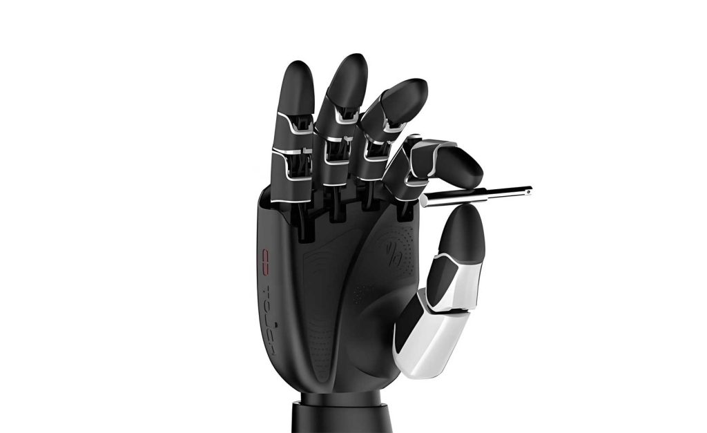
The mechanical architecture of the dexterous robotic hand is meticulously crafted to mirror the key aspects of human hand morphology while ensuring practicality for robotic implementation. Human fingers, though diverse in size and function, share a common skeletal structure comprising three phalanges (distal, middle, and proximal) interconnected by three joints (distal interphalangeal, proximal interphalangeal, and metacarpophalangeal). To simplify design and control, I adopt a homogeneous configuration where all three fingers of the dexterous robotic hand are structurally identical, each consisting of three links corresponding to the phalanges and three revolute joints enabling flexion and extension. Additionally, a base joint at the finger root provides abduction/adduction motion, resulting in a total of four degrees of freedom per finger. The wrist, however, is designed with enhanced rotational capability, allowing for continuous 360-degree rotation to maximize dexterity and reach. This dexterous robotic hand is intended to perform a wide range of tasks, from precision pinching to power grasping, making it a versatile tool for robotic manipulation. The design parameters for each finger segment are summarized in Table 1, detailing lengths, allowable rotation angles, and actuation methods. These parameters are derived from anthropometric studies and engineering constraints to balance functionality, strength, and weight.
| Link Name | Length (mm) | Rotation Angle (°) | Actuation Method |
|---|---|---|---|
| Distal Phalanx (Fingertip) | 35 | 0 – 90 | Electric Motor |
| Middle Phalanx | 45 | 0 – 90 | Electric Motor |
| Proximal Phalanx | 60 | 0 – 90 | Electric Motor |
| Base Joint (Abduction/Adduction) | — | 0 – 90 | Electric Motor |
To model the kinematic behavior of the dexterous robotic hand, I employ the Denavit-Hartenberg (D-H) convention, a widely used method in robotics for representing the geometry of serial chain mechanisms. This approach assigns coordinate frames to each joint and defines parameters to describe the spatial relationship between successive frames. For the dexterous robotic hand, I analyze a single finger as a three-link manipulator (excluding the base abduction joint for initial simplicity), where the fingertip position and orientation can be determined from the joint angles. The coordinate systems are established as follows: a fixed reference frame \( \{0\} \) is attached to the base of the finger, and moving frames \( \{1\} \), \( \{2\} \), and \( \{3\} \) are attached to the proximal, middle, and distal joints, respectively. The D-H parameters for the finger mechanism are listed in Table 2, where \( \theta_i \) denotes the joint angle, \( \alpha_i \) the twist angle, \( a_i \) the link length, and \( d_i \) the link offset. Note that for this dexterous robotic hand, all joints are revolute, and the twist angles are set based on the anatomical alignment of human finger joints.
| Link \( i \) | \( \theta_i \) (°) | \( \alpha_i \) (°) | \( a_i \) (mm) | \( d_i \) (mm) |
|---|---|---|---|---|
| 1 | \( \theta_1 \) | 90 | \( a_1 = 60 \) | 0 |
| 2 | \( \theta_2 \) | 0 | \( a_2 = 45 \) | 0 |
| 3 | \( \theta_3 \) | 0 | \( a_3 = 35 \) | 0 |
The homogeneous transformation matrix \( A_i \) for each link, which maps frame \( \{i\} \) to frame \( \{i-1\} \), is given by the standard D-H formula:
$$ A_i = \text{Rot}(z, \theta_i) \times \text{Trans}(0, 0, d_i) \times \text{Trans}(a_i, 0, 0) \times \text{Rot}(x, \alpha_i) $$
This expands to:
$$ A_i = \begin{bmatrix}
\cos\theta_i & -\sin\theta_i \cos\alpha_i & \sin\theta_i \sin\alpha_i & a_i \cos\theta_i \\
\sin\theta_i & \cos\theta_i \cos\alpha_i & -\cos\theta_i \sin\alpha_i & a_i \sin\theta_i \\
0 & \sin\alpha_i & \cos\alpha_i & d_i \\
0 & 0 & 0 & 1
\end{bmatrix} $$
Substituting the parameters from Table 2 yields the individual transformation matrices for the dexterous robotic hand finger:
$$ A_1 = \begin{bmatrix}
\cos\theta_1 & 0 & \sin\theta_1 & a_1 \cos\theta_1 \\
\sin\theta_1 & 0 & -\cos\theta_1 & a_1 \sin\theta_1 \\
0 & 1 & 0 & 0 \\
0 & 0 & 0 & 1
\end{bmatrix} $$
$$ A_2 = \begin{bmatrix}
\cos\theta_2 & -\sin\theta_2 & 0 & a_2 \cos\theta_2 \\
\sin\theta_2 & \cos\theta_2 & 0 & a_2 \sin\theta_2 \\
0 & 0 & 1 & 0 \\
0 & 0 & 0 & 1
\end{bmatrix} $$
$$ A_3 = \begin{bmatrix}
\cos\theta_3 & -\sin\theta_3 & 0 & a_3 \cos\theta_3 \\
\sin\theta_3 & \cos\theta_3 & 0 & a_3 \sin\theta_3 \\
0 & 0 & 1 & 0 \\
0 & 0 & 0 & 1
\end{bmatrix} $$
The overall transformation matrix from the fingertip frame \( \{3\} \) to the base frame \( \{0\} \) is obtained by consecutive multiplication:
$$ T^0_3 = A_1 A_2 A_3 $$
Carrying out the matrix multiplication, the position and orientation of the fingertip can be expressed as functions of the joint angles. Let \( c_i = \cos\theta_i \), \( s_i = \sin\theta_i \), \( c_{ij} = \cos(\theta_i + \theta_j) \), and \( s_{ij} = \sin(\theta_i + \theta_j) \). Then:
$$ T^0_3 = \begin{bmatrix}
c_1 c_{23} & -c_1 s_{23} & s_1 & a_3 c_1 c_{23} + a_2 c_1 c_2 + a_1 c_1 \\
s_1 c_{23} & -s_1 s_{23} & -c_1 & a_3 s_1 c_{23} + a_2 s_1 c_2 + a_1 s_1 \\
s_{23} & c_{23} & 0 & a_3 s_{23} + a_2 s_2 \\
0 & 0 & 0 & 1
\end{bmatrix} $$
Here, the fingertip coordinates \( (p_x, p_y, p_z) \) in the base frame are given by:
$$ p_x = a_3 c_1 c_{23} + a_2 c_1 c_2 + a_1 c_1 $$
$$ p_y = a_3 s_1 c_{23} + a_2 s_1 c_2 + a_1 s_1 $$
$$ p_z = a_3 s_{23} + a_2 s_2 $$
These equations form the forward kinematics model of the dexterous robotic hand finger, enabling the computation of fingertip position for any set of joint angles. To validate this model and visualize the motion, I performed simulations using Adams software. A virtual prototype of the dexterous robotic hand was constructed, and various finger postures were simulated to analyze the workspace and displacement characteristics. For instance, during a bending motion from an extended to a flexed configuration, the trajectory of the fingertip relative to the base joint was recorded. The simulation results confirm that the dexterous robotic hand has a substantial workspace, allowing it to reach points within a hemispherical region, which is essential for dexterous manipulation tasks. The smooth transition of positions indicates that the kinematic design is feasible for generating natural, human-like movements.
Beyond kinematics, understanding the dynamic behavior of the dexterous robotic hand is critical for designing controllers that can handle inertial forces, gravity, and external loads during operation. Dynamics deals with the relationship between forces/torques and motion, encompassing mass, inertia, and energy considerations. For the dexterous robotic hand, I derive the dynamic model using the Lagrange-Euler formulation, which is based on energy principles and provides a systematic way to obtain the equations of motion. The Lagrangian \( L \) is defined as the difference between kinetic energy \( K \) and potential energy \( P \) of the system:
$$ L = K – P $$
The kinetic energy for a multi-link system like the dexterous robotic hand finger can be expressed as:
$$ K = \frac{1}{2} \sum_{i=1}^{n} \left( m_i \mathbf{v}_i^T \mathbf{v}_i + \boldsymbol{\omega}_i^T \mathbf{I}_i \boldsymbol{\omega}_i \right) $$
where \( m_i \) is the mass of link \( i \), \( \mathbf{v}_i \) is the linear velocity of its center of mass, \( \boldsymbol{\omega}_i \) is the angular velocity, and \( \mathbf{I}_i \) is the inertia tensor. The potential energy, primarily due to gravity, is:
$$ P = \sum_{i=1}^{n} m_i g h_i $$
with \( g \) as gravitational acceleration and \( h_i \) the height of the center of mass. Applying Lagrange’s equations:
$$ \frac{d}{dt} \left( \frac{\partial L}{\partial \dot{q}_j} \right) – \frac{\partial L}{\partial q_j} = \tau_j, \quad j = 1, 2, 3 $$
where \( q_j \) are the generalized coordinates (joint angles \( \theta_1, \theta_2, \theta_3 \)), \( \dot{q}_j \) are the joint velocities, and \( \tau_j \) are the generalized forces (joint torques). This leads to the standard dynamic equation for the dexterous robotic hand:
$$ \boldsymbol{\tau}(t) = \mathbf{D}(\mathbf{q}(t)) \ddot{\mathbf{q}}(t) + \mathbf{h}(\mathbf{q}(t), \dot{\mathbf{q}}(t)) + \mathbf{c}(\mathbf{q}(t)) $$
Here, \( \boldsymbol{\tau} = [\tau_1, \tau_2, \tau_3]^T \) is the torque vector, \( \mathbf{q} = [\theta_1, \theta_2, \theta_3]^T \) is the joint angle vector, \( \ddot{\mathbf{q}} \) is the acceleration vector, \( \mathbf{D}(\mathbf{q}) \) is the \( 3 \times 3 \) inertia matrix (symmetric and positive-definite), \( \mathbf{h}(\mathbf{q}, \dot{\mathbf{q}}) \) is the \( 3 \times 1 \) vector of Coriolis and centrifugal forces, and \( \mathbf{c}(\mathbf{q}) \) is the \( 3 \times 1 \) vector of gravitational forces. The elements of these matrices are complex functions of the link masses, lengths, and inertial properties. For the dexterous robotic hand finger, with masses \( m_1 = 0.2697 \, \text{kg} \) (proximal), \( m_2 = 0.1637 \, \text{kg} \) (middle), and \( m_3 = 0.1054 \, \text{kg} \) (distal), and lengths as in Table 1, the explicit forms can be derived but are omitted here for brevity. The dynamic model captures the nonlinear and coupled nature of the system, which is characteristic of multi-degree-of-freedom manipulators like this dexterous robotic hand.
To analyze the dynamic performance, I conducted simulations in Adams for a common finger motion: flexion from a fully extended to a fully bent position. Two scenarios were considered: (1) with only gravitational forces acting on the finger links, and (2) with an additional external force applied at the fingertip, simulating contact with an object. The joint torques required to achieve this motion under constant angular velocity were computed. The results are summarized in Table 3 for the case with gravity only, and Table 4 for cases with external forces of 5 N and 10 N. These tables provide maximum torque values and trends, highlighting the load-bearing capabilities of the dexterous robotic hand.
| Joint | Maximum Torque (N·mm) | Time of Maximum (s) | Zero-Torque Instances |
|---|---|---|---|
| Proximal (Joint 2) | 337.05 | 0 | Yes |
| Middle (Joint 3) | 94.75 | 0 | Yes |
| Distal (Joint 4) | 14.51 | 0 | Yes |
The torque profiles show that initial torques are highest due to the largest moment arms at the start of motion. As the finger flexes, torques vary smoothly, sometimes reaching zero when gravitational forces align with joint axes or when inertial effects balance out. This behavior underscores the importance of dynamic modeling for efficient control of the dexterous robotic hand.
| External Force (N) | Max Torque at Joint 2 (N·mm) | Max Torque at Joint 3 (N·mm) | Max Torque at Joint 4 (N·mm) |
|---|---|---|---|
| 5 | 1037.00 | 491.32 | 189.51 |
| 10 | 1737.00 | 887.89 | 364.51 |
With external forces, torques increase significantly, as expected, since the motors must counteract both internal and external loads. These values are crucial for selecting appropriate actuators for the dexterous robotic hand. For instance, electric motors with sufficient torque output, possibly with gear reduction, must be chosen to handle peak loads during grasping or manipulation tasks. The simulation curves, though not displayed here, exhibit smooth transitions, indicating that the dynamic model is well-behaved and suitable for real-time control implementations. Furthermore, the dexterous robotic hand demonstrates robustness in maintaining motion profiles under varying loads, a desirable trait for adaptive grasping.
In addition to single-finger analyses, the integration of multiple fingers into a coordinated dexterous robotic hand system introduces complexities in kinematics and dynamics due to interactions between fingers and with grasped objects. However, the modular design with identical fingers simplifies this to some extent. The forward kinematics for each finger can be combined to describe the overall hand posture, and inverse kinematics algorithms can be developed to position fingertips for specific grasps. For dynamics, coupling effects between fingers via the palm are minimal if the palm is rigid, but object contact forces create closed-chain constraints that must be addressed using methods like constrained dynamics or virtual work principles. Future work on this dexterous robotic hand will involve implementing such multi-finger coordination models and validating them through advanced simulations and experimental prototypes.
From a control perspective, the derived models provide the foundation for designing controllers that ensure precise trajectory tracking and force regulation. For example, computed-torque control or sliding mode control can utilize the dynamic equation to compensate for nonlinearities and disturbances. The dexterous robotic hand, with its multiple degrees of freedom, offers redundancy that can be exploited for optimizing grasp stability or minimizing energy consumption. Techniques from machine learning, such as reinforcement learning, could also be applied to teach the dexterous robotic hand complex manipulation skills autonomously. The synergy between mechanical design, modeling, and control is what will ultimately enable this dexterous robotic hand to perform dexterous tasks akin to human hands.
In conclusion, this study presents a comprehensive analysis of the kinematics and dynamics of a three-fingered dexterous robotic hand. Through detailed modeling using D-H parameters and Lagrange-Euler formulations, coupled with Adams simulations, I have demonstrated that the proposed design is mechanically sound and capable of dexterous manipulations. The kinematic model accurately predicts fingertip positions, while the dynamic model reveals torque requirements under various loading conditions. These insights are vital for actuator selection, control system design, and performance optimization of the dexterous robotic hand. The versatility of this dexterous robotic hand makes it suitable for applications in robotics research, industrial automation, and service robotics, where human-like manipulation is essential. Future endeavors will focus on experimental validation, enhanced wrist mechanisms, and integration with sensory feedback for adaptive grasping. As robotics continues to evolve, dexterous robotic hands like the one described here will play a pivotal role in bridging the gap between machines and humans, enabling robots to interact with the world in more nuanced and effective ways.
To further elaborate on the mathematical underpinnings, consider the inverse kinematics problem for the dexterous robotic hand: determining joint angles for a desired fingertip position. This involves solving nonlinear equations derived from the forward kinematics. For a given \( (p_x, p_y, p_z) \), one can derive expressions for \( \theta_1 \), \( \theta_2 \), and \( \theta_3 \). For instance, from the forward kinematics equations:
$$ \theta_1 = \atan2(p_y, p_x) \quad \text{(assuming } a_1 \text{ is accounted for)} $$
Then, using geometric methods, \( \theta_2 \) and \( \theta_3 \) can be found by solving:
$$ p_z = a_3 \sin(\theta_2 + \theta_3) + a_2 \sin\theta_2 $$
$$ r = \sqrt{p_x^2 + p_y^2} – a_1 = a_3 \cos(\theta_2 + \theta_3) + a_2 \cos\theta_2 $$
where \( r \) is the planar distance. This system can be solved using trigonometric identities, yielding multiple solutions due to the elbow-up and elbow-down configurations. Such inverse kinematics solutions are essential for path planning of the dexterous robotic hand.
Regarding dynamics, the inertia matrix \( \mathbf{D}(\mathbf{q}) \) for the dexterous robotic hand finger can be computed symbolically. For a three-link planar manipulator (ignoring abduction for simplicity), the elements are:
$$ D_{11} = I_1 + I_2 + I_3 + m_1 l_{c1}^2 + m_2 (a_1^2 + l_{c2}^2 + 2 a_1 l_{c2} \cos\theta_2) + m_3 (a_1^2 + a_2^2 + l_{c3}^2 + 2 a_1 a_2 \cos\theta_2 + 2 a_1 l_{c3} \cos(\theta_2+\theta_3) + 2 a_2 l_{c3} \cos\theta_3) $$
$$ D_{12} = I_2 + I_3 + m_2 (l_{c2}^2 + a_1 l_{c2} \cos\theta_2) + m_3 (a_2^2 + l_{c3}^2 + a_1 a_2 \cos\theta_2 + a_1 l_{c3} \cos(\theta_2+\theta_3) + 2 a_2 l_{c3} \cos\theta_3) $$
$$ D_{13} = I_3 + m_3 (l_{c3}^2 + a_1 l_{c3} \cos(\theta_2+\theta_3) + a_2 l_{c3} \cos\theta_3) $$
$$ D_{22} = I_2 + I_3 + m_2 l_{c2}^2 + m_3 (a_2^2 + l_{c3}^2 + 2 a_2 l_{c3} \cos\theta_3) $$
$$ D_{23} = I_3 + m_3 (l_{c3}^2 + a_2 l_{c3} \cos\theta_3) $$
$$ D_{33} = I_3 + m_3 l_{c3}^2 $$
where \( I_i \) are link inertias about their centers of mass, and \( l_{ci} \) are distances from joint \( i \) to the center of mass of link \( i \). The Coriolis and centrifugal vector \( \mathbf{h} \) contains terms like \( \dot{\theta}_i \dot{\theta}_j \) and \( \dot{\theta}_i^2 \), while the gravity vector \( \mathbf{c} \) depends on \( \sin(\theta_2) \) and \( \sin(\theta_2+\theta_3) \). These equations highlight the complexity inherent in controlling a dexterous robotic hand.
In simulation, the Adams software solves these equations numerically, providing torque profiles over time. For the flexion motion with gravity only, the torques decrease from initial peaks as the finger moves, reflecting changes in moment arms. With external forces, the torques scale approximately linearly with the force magnitude, emphasizing the need for robust actuators in a dexterous robotic hand intended for object manipulation. These dynamics simulations also allow for optimization of link masses and geometries to reduce required torques and improve energy efficiency.
Another aspect is the workspace analysis of the dexterous robotic hand. By varying joint angles within limits, the reachable points of the fingertip form a volume in space. For a single finger with the given parameters, the workspace can be approximated as a portion of a spherical shell. Combining three fingers extends this workspace significantly, enabling the dexterous robotic hand to grasp objects of various sizes and shapes. The dexterity can be quantified using measures like manipulability ellipsoids derived from the Jacobian matrix, which relates joint velocities to fingertip velocities. The Jacobian \( \mathbf{J} \) for the finger is obtained by differentiating the forward kinematics:
$$ \mathbf{J} = \begin{bmatrix}
\frac{\partial p_x}{\partial \theta_1} & \frac{\partial p_x}{\partial \theta_2} & \frac{\partial p_x}{\partial \theta_3} \\
\frac{\partial p_y}{\partial \theta_1} & \frac{\partial p_y}{\partial \theta_2} & \frac{\partial p_y}{\partial \theta_3} \\
\frac{\partial p_z}{\partial \theta_1} & \frac{\partial p_z}{\partial \theta_2} & \frac{\partial p_z}{\partial \theta_3}
\end{bmatrix} $$
For the dexterous robotic hand, this matrix is configuration-dependent, and its singularities indicate loss of dexterity. Avoiding singularities is important for smooth control.
In summary, the development of this dexterous robotic hand involves a holistic approach combining mechanical design, kinematic modeling, dynamic analysis, and simulation. Each component is critical for ensuring that the final system can perform dexterous tasks reliably. The use of Adams software validates the models and provides practical insights into torque requirements and motion characteristics. As robotics technology advances, dexterous robotic hands will become increasingly sophisticated, incorporating sensors for tactile feedback, adaptive control algorithms, and learning capabilities. This work contributes to that progression by establishing a solid analytical and simulation framework for a three-fingered dexterous robotic hand. The journey from concept to realization of such a dexterous robotic hand is challenging but rewarding, offering the promise of robots that can interact with their environment as skillfully as humans do.