
In modern industrial applications, the cycloidal drive has emerged as a pivotal component due to its exceptional performance characteristics. As I delve into this topic, it becomes clear that understanding the intricacies of cycloidal drives is essential for ensuring their longevity and reliability. These drives, based on the principle of cycloidal motion and planetary gear systems, offer significant advantages over traditional gear reducers, including high reduction ratios, compact size, and smooth operation. However, like any mechanical system, they are susceptible to wear and tear, making proactive maintenance and care crucial. In this article, I will explore the fundamental principles, common faults, and comprehensive maintenance strategies for cycloidal drives, aiming to provide a detailed guide that underscores the importance of regular upkeep. By integrating tables and mathematical formulas, I hope to offer a thorough resource that emphasizes the keyword ‘cycloidal drive’ throughout, reinforcing its relevance in industrial contexts.
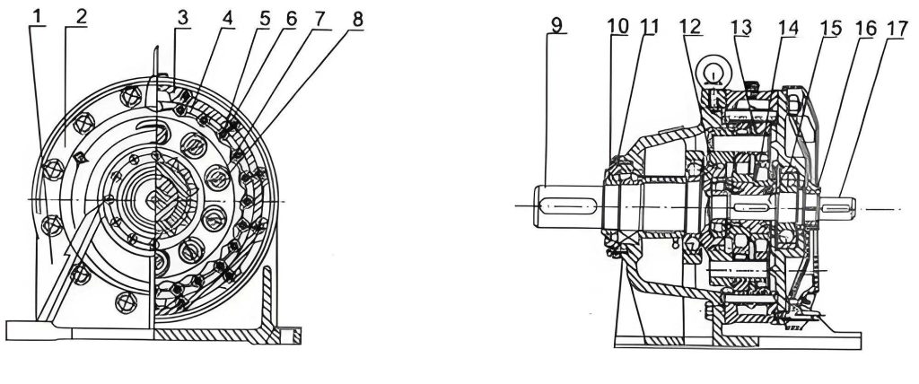
The cycloidal drive operates on a fascinating mechanism that leverages cycloidal curves to achieve precise motion control. At its core, a cycloidal drive consists of three main components: an input shaft, a reduction assembly, and an output shaft. The input shaft typically features an eccentric sleeve with a double offset, which rotates to drive the cycloidal discs. These discs engage with pin gears in a hypocycloidal motion, resulting in a high reduction ratio. The mathematical foundation of this motion can be described using parametric equations for the cycloidal curve. For instance, the path of a point on the cycloidal disc relative to the pin gear can be expressed as:
$$ x = (R – r) \cos \theta + a \cos\left(\frac{R – r}{r} \theta\right) $$
$$ y = (R – r) \sin \theta – a \sin\left(\frac{R – r}{r} \theta\right) $$
Here, \( R \) represents the radius of the pin gear circle, \( r \) is the radius of the cycloidal disc, \( a \) is the eccentricity distance, and \( \theta \) is the input rotation angle. This equation highlights the complex interaction that enables the cycloidal drive to achieve smooth and efficient power transmission. The reduction ratio \( i \) of a cycloidal drive is determined by the number of pins \( Z_p \) on the gear and the number of lobes \( Z_c \) on the cycloidal disc, often given by:
$$ i = \frac{Z_p}{Z_p – Z_c} $$
This formula shows that a single-stage cycloidal drive can achieve high reduction ratios, often exceeding 100:1, making it ideal for applications requiring slow output speeds with high torque. The operation involves the eccentric sleeve rotating with the input shaft, causing the cycloidal discs to undergo both revolution and rotation. When the input shaft completes one full rotation, the cycloidal disc moves in the opposite direction by one lobe, effectively reducing speed. This motion is then transmitted to the output shaft via a wrist-pin mechanism, ensuring stable and reliable performance. The efficiency of a cycloidal drive typically ranges from 90% to 95%, attributed to the rolling contact between components, which minimizes friction compared to sliding contacts in conventional gears. To illustrate the design parameters, consider the following table summarizing key variables in cycloidal drive systems:
| Parameter | Symbol | Typical Range | Description |
|---|---|---|---|
| Pin Gear Radius | \( R \) | 50-200 mm | Radius of the circle formed by pin centers |
| Cycloidal Disc Radius | \( r \) | 45-190 mm | Radius of the cycloidal disc profile |
| Eccentricity | \( a \) | 1-5 mm | Offset distance for eccentric motion |
| Number of Pins | \( Z_p \) | 10-50 | Total pins on the gear |
| Number of Lobes | \( Z_c \) | \( Z_p – 1 \) | Lobes on the cycloidal disc |
| Reduction Ratio | \( i \) | 10:1 to 100:1 | Ratio of input to output speed |
Understanding these parameters is vital for diagnosing issues in cycloidal drives. Common faults often stem from prolonged operation or inadequate maintenance. For instance, the eccentric sleeve keyway is prone to damage due to continuous use or frequent start-stop cycles. Similarly, the pin shaft keyway can wear out, leading to misalignment and reduced efficiency. When such faults occur, immediate action is required, such as replacing the eccentric sleeve or machining a new keyway in a symmetric position. Another frequent issue involves the bearing assemblies, particularly the roller bearings on the eccentric sleeve, which may fail if lubrication is insufficient. The pin sleeves can also suffer from excessive wear under overload conditions, necessitating replacement with components from the same manufacturer to ensure compatibility. Below is a table that outlines common faults in cycloidal drives, along with their symptoms and recommended handling measures:
| Fault Type | Symptoms | Causes | Handling Measures |
|---|---|---|---|
| Eccentric Sleeve Keyway Damage | Abnormal noise, vibration | Prolonged use, frequent cycling | Replace sleeve or machine new keyway |
| Pin Shaft Keyway Wear | Output speed fluctuations | High torque loads, misalignment | Replace shaft or reprofile keyway |
| Bearing Failure | Overheating, grinding sounds | Poor lubrication, contamination | Replace bearings and improve lubrication |
| Pin Sleeve Damage | Reduced torque transmission | Overload, abrasive particles | Replace sleeves with OEM parts |
| Seal Degradation | Oil leaks, dirt ingress | Aging, thermal stress | Install new seals and clean housing |
To mitigate these faults, a robust maintenance regimen is essential for cycloidal drives. The cornerstone of maintenance lies in lubrication management. After initial oil filling, the lubricant should be replaced after the first 100 hours of operation to remove break-in debris. Subsequent changes depend on operational hours and environmental conditions. For drives operating 8 hours daily in clean environments, oil changes every six months are typical. However, in harsh conditions or with extended shifts, intervals should be shortened to as little as three months. The oil change process must include thorough cleaning of the internal housing to eliminate residual oil and metal particles, which can accelerate wear. The oil quality is equally critical; using high-grade lubricants with anti-wear additives can enhance the lifespan of the cycloidal drive. Additionally, the oil level must be checked regularly to prevent both under-lubrication and overfilling. The following table provides a detailed maintenance schedule for cycloidal drives:
| Maintenance Task | Frequency | Procedure | Key Considerations |
|---|---|---|---|
| Oil Change | Every 3-6 months | Drain old oil, clean housing, refill | Use specified oil grade; avoid mixing types |
| Bolt Tightening | Monthly | Check and torque all fasteners | Focus on base and coupling bolts |
| Alignment Check | Quarterly | Measure coupling concentricity | Use dial indicators; limit misalignment to 0.05 mm |
| Seal Inspection | Every 6 months | Visual check for leaks or wear | Replace if cracks or hardening observed |
| Temperature Monitoring | Daily | Record operating temperature | Alert if exceeding 70°C; investigate causes |
| Noise Assessment | Weekly | Listen for unusual sounds | Indicates bearing or gear issues |
Beyond lubrication, other mechanical aspects demand attention. The coupling alignment between the cycloidal drive and connected machinery must be precise to avoid non-torsional forces that can damage components. Regular checks using laser alignment tools or dial gauges are recommended, with tolerances often kept within 0.05 mm. Fasteners, including base bolts and housing screws, should be inspected monthly for loosening, as vibrations from operation can cause them to slacken, leading to imbalance or even catastrophic failure. The cycloidal drive’s internal components, such as the cycloidal discs and pin gears, require periodic examination for wear patterns. Wear can be quantified using the formula for contact stress \( \sigma_c \):
$$ \sigma_c = \sqrt{\frac{F}{L} \cdot \frac{E}{2 \pi (1 – \nu^2)} \cdot \frac{1}{R_e}} $$
where \( F \) is the contact force, \( L \) is the contact length, \( E \) is the modulus of elasticity, \( \nu \) is Poisson’s ratio, and \( R_e \) is the equivalent radius of curvature. Monitoring this stress helps predict fatigue life and schedule replacements proactively. When replacing parts like the eccentric bearing, careful techniques are necessary; for example, using two pry bars at symmetric points to apply balanced force prevents damage to adjacent components. Unbalanced force or hammering should be avoided, as it can distort the housing or misalign the cycloidal drive assembly.
Environmental factors also play a role in cycloidal drive maintenance. In dusty or humid settings, seals must be checked more frequently to prevent contamination ingress, which can abrade surfaces and degrade lubrication. The operating temperature should remain below 70°C; if overheating occurs, it may indicate internal friction due to misalignment, inadequate lubrication, or component failure. Noise analysis is another diagnostic tool; unusual sounds like grinding or clicking often point to bearing wear or pin sleeve damage. Implementing a predictive maintenance approach, such as vibration analysis or oil spectroscopy, can detect early signs of wear in cycloidal drives, allowing for timely interventions. For instance, vibration frequency spectra can reveal imbalances or meshing issues, with dominant frequencies related to the cycloidal motion given by:
$$ f_m = \frac{Z_c \cdot n}{60} $$
Here, \( f_m \) is the meshing frequency in Hz, \( Z_c \) is the number of lobes, and \( n \) is the input speed in RPM. Deviations from baseline spectra can signal faults. Additionally, maintaining detailed logs of all maintenance activities enables trend analysis, helping to optimize schedules and reduce downtime. A well-documented history for each cycloidal drive can reveal patterns, such as increased oil consumption or frequent bearing failures, guiding improvements in operation or design.
In conclusion, the cycloidal drive is a sophisticated mechanical system that demands diligent care to maximize its service life and performance. Its compact design, while advantageous, complicates maintenance due to intricate internal geometry. Therefore, skilled technicians with expertise in cycloidal drives are essential for proper servicing. By adhering to a structured maintenance plan that includes regular lubrication, alignment checks, and component inspections, operators can prevent common faults and ensure reliable operation. Emphasizing the keyword ‘cycloidal drive’ throughout this discussion underscores its importance in industrial applications, from robotics to heavy machinery. Future advancements may integrate IoT sensors for real-time monitoring of cycloidal drives, enabling predictive maintenance and further reducing failure risks. Ultimately, investing in thorough maintenance not only extends the lifespan of cycloidal drives but also enhances overall system efficiency, contributing to cost savings and operational safety in diverse industries.