
The evolution of surgical paradigms has been profoundly influenced by the integration of robotic systems, offering unprecedented precision, stability, and dexterity beyond human physiological limits. In the domain of microsurgery, where manipulations on sub-millimeter anatomical structures like blood vessels and nerves are routine, the role of medical robot systems becomes critically enabling. A fundamental and ubiquitous task in any surgical procedure, robotic or manual, is the act of grasping—whether it be to hold a suture needle, manipulate tissue, or apply a clip. In a master-slave teleoperated medical robot, replicating this intuitive grasp action with high fidelity and low latency is paramount for surgical efficacy and safety. This article details the comprehensive design and successful implementation of a real-time master-slave grasping control system, architected around a high-performance ARM microcontroller, for our laboratory’s proprietary microsurgical robotic system.
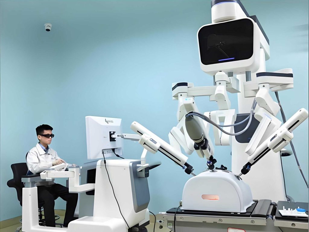
The core of our system is a teleoperated medical robot designed for microsurgery, nicknamed “Skilled Hand.” Its operational philosophy is based on a master-slave configuration, where a surgeon’s movements at a master console are scaled, filtered, and precisely reproduced by robotic instruments (the slave) inside the patient’s body. While the system encompasses multi-degree-of-freedom control for position and orientation, this discussion focuses specifically on the unilateral control of the end-effector’s grasping function. The challenge was to create a seamless, responsive interface where the opening and closing of the surgeon’s fingers on a master interface is accurately and reliably translated to the opening and closing of a micro-grasper attached to the slave medical robot.
Selecting the right computational core was the first critical decision. Earlier implementations in robotic systems often relied on microcontrollers (MCUs) or Digital Signal Processors (DSPs). However, the computational demands for modern teleoperation—involving signal processing, control algorithm execution, and potential network communication—require greater processing power and richer peripheral resources. ARM-based microcontrollers emerged as the optimal solution. They offer a compelling blend of high-speed processing, typically measured in hundreds of MIPS (Millions of Instructions Per Second), low power consumption, and a vast array of integrated peripherals like memory controllers, communication interfaces, and timers. This makes them exceptionally well-suited for the embedded brains of a complex medical robot control system, balancing real-time performance with functional complexity.
1. System Architecture and Requirements
The master-slave grasping system is a cyber-physical loop comprising three primary physical subsystems and the control intelligence that binds them. The design requirements were stringent, driven by the needs of microsurgery.
| Subsystem | Description | Key Requirement |
|---|---|---|
| Master Input Device | A 6-DOF articulated manipulator with a specialized pinch-grasp mechanism at its tip. The surgeon places thumb and index finger into a rotor and stator thimble. | Provide high-resolution, low-friction analog measurement of the pinch angle. |
| Control System | The electronic hardware and software core based on an ARM microcontroller. | Acquire master signal, compute control law, generate drive signals with minimal latency (< 1 ms for this sub-task). |
| Slave Actuator | A modular finger assembly for the slave medical robot, containing a micro stepper motor driving a paired grasper via a transmission. | Precisely translate electrical pulses into angular displacement of the grasper jaws. |
The operational sequence is a closed-loop process, though the position loop is closed around the master input rather than direct feedback from the slave grasper (open-loop in slave position). The master’s pinch mechanism incorporates a rotary potentiometer. The relative angular displacement $\theta_m(t)$ between the thimbles creates a proportional analog voltage $V_m(t)$:
$$V_m(t) = k_p \cdot \theta_m(t) + V_{offset}$$
where $k_p$ is the potentiometer’s gain (Volts/radian). This voltage is sampled by the control system. The controller’s role is to map this sampled master command $\hat{\theta}_m[n]$ to a required number of stepper motor pulses $N_s[n]$ for the slave actuator. Assuming a linear relationship and a scaling factor $K_{scale}$ (which can be less than, equal to, or greater than 1 for motion scaling):
$$\theta_s^{desired}[n] = K_{scale} \cdot \hat{\theta}_m[n]$$
If the stepper motor has a step angle $\phi$ (degrees/step) and the transmission has a gear ratio $G_r$, the angular displacement of the grasper per step is:
$$\Delta\theta_s = \frac{\phi}{G_r}$$
Thus, the required number of steps from a known initial position is:
$$N_s[n] = \frac{\theta_s^{desired}[n] – \theta_s[n-1]}{\Delta\theta_s}$$
The controller must generate these $N_s[n]$ pulses with appropriate acceleration/deceleration profiling.
2. Hardware Design of the Control System
The hardware platform was built to be robust, precise, and capable of supporting real-time Linux, which was chosen for its stability, networking support, and driver model.
2.1 ARM Microcontroller Platform Core
We selected the AT91RM9200 from Microchip (formerly Atmel), an industrial-grade ARM920T core-based microcontroller. Its specifications were ideal for a medical robot controller:
- Processor: ARM920T core running at 180 MHz, delivering up to 200 MIPS.
- Memory Interface: Integrated SDRAM and Static Memory Controllers for external RAM and Flash.
- Peripherals: Rich set including 10/100 Ethernet, USB 2.0, multiple serial ports (USARTs), SPI, I²C, and crucially, four 32-bit Parallel I/O (PIO) controllers with 122 programmable I/O lines.
- Real-time Capability: Multiple interval timers, a watchdog timer, and interrupt controller essential for deterministic response.
The minimal system design expanded around this core included:
1. Power Supply: Provided stable 3.3V for I/O and 1.8V for the core.
2. Memory: 32 MB of SDRAM for operating system and program execution; 16 MB of NOR Flash for bootloader, Linux kernel, and root filesystem storage.
3. Debugging Interface: A JTAG port for low-level debugging and bootstrapping.
4. Serial Console: A UART interface for system debugging and monitoring.
This platform formed the computational bedrock upon which the specific grasping I/O modules were integrated.
2.2 Analog-to-Digital Conversion (ADC) Module
To digitize the master potentiometer’s analog voltage, we needed an ADC with sufficient speed, resolution, and a simple interface. A serial ADC connected via the SPI bus was chosen for its compact interface. The AD7467, a 10-bit, single-channel, high-speed, low-power ADC from Analog Devices, was perfect. Key equations governing its operation:
– The reference voltage $V_{REF}$ is derived from the power supply $AV_{DD}$.
– The digital output code $D_{out}$ for an input voltage $V_{in}$ is:
$$D_{out} = \frac{V_{in}}{AV_{DD}} \cdot 2^{10} = \frac{V_{in}}{AV_{DD}} \cdot 1024$$
– The master pinch angle is then recovered as:
$$\hat{\theta}_m = \frac{D_{out} \cdot AV_{DD}}{1024 \cdot k_p} – \frac{V_{offset}}{k_p}$$
The hardware connection was straightforward: the potentiometer’s wiper output connected to the AD7467’s analog input pin. The SPI interface of the AT91RM9200 connected to the ADC’s serial clock (SCLK), data output (SDO), and chip select (CS) pins. The ADC’s conversion is initiated by the SPI clock itself, simplifying the driver software.
2.3 Stepper Motor Drive Module
The slave grasper is actuated by a miniature bipolar stepper motor (AM1020). Driving it requires a dedicated circuit to convert low-voltage logic pulses into high-current phase currents. We employed a classic and robust “translator-driver” combination: the L297 (translator/controller) and L298N (dual full-bridge driver).
The L297 generates the proper phase sequencing signals (for wave drive, half-step, or full-step modes) based on two primary inputs from the microcontroller: a STEP pulse and a DIRECTION signal. The number of STEP pulses dictates the rotation; the DIRECTION level sets the polarity. The L298N acts as the power stage, sourcing the current (up to 2A per bridge) to the motor windings as directed by the L297’s phase outputs.
To protect the microcontroller from electrical noise and level-shift the 3.3V signals to the 5V expected by the L297, we placed high-speed optocouplers (6N137) on the STEP, DIRECTION, and enable lines. This provided galvanic isolation. The drive voltage for the motor ($V_{motor}$ = 12V) was separate from the logic supplies. A critical design aspect was current sensing and regulation. The L297 features built-in pulse-width modulation (PWM) chopper control for constant current driving. The current limit $I_{max}$ is set by a sense resistor $R_s$ and a reference voltage $V_{ref}$:
$$I_{max} = \frac{V_{ref}}{R_s}$$
This prevents motor overheating and ensures consistent torque regardless of winding resistance variations.
| Module | Component | Key Parameter/Value | Function in medical robot Grasping |
|---|---|---|---|
| Core Controller | AT91RM9200 | 180 MHz, 200 MIPS, ARM920T | Central processor running Linux and control algorithms. |
| Analog Front-end | AD7467 ADC | 10-bit, 200 kSPS, SPI | Digitizes master surgeon’s pinch angle. |
| Power Driver | L297 + L298N | $I_{out}$=2A, $V_{out}$=46V, Chopper Control | Translates logic commands to power for the slave micro-stepper motor. |
| Isolation | 6N137 Optocoupler | 10 MBd | Protects CPU from motor driver electrical noise. |
| Actuator | AM1020 Stepper Motor | 12V, 18° step angle, Bipolar | Primary actuator for slave grasper jaws. |
3. Software Architecture and Implementation
The software was structured to leverage the real-time capabilities of a standard Linux kernel (version 2.4.26) through meticulous driver design and user-space application logic.
3.1 Linux Device Drivers
To achieve low-latency access to the hardware, kernel-space device drivers were developed for both the ADC and the stepper motor controller.
3.1.1 ADC Driver: This driver exposed the AD7467 as a character device (e.g., `/dev/adc_grasp`). Its internal operation was an interrupt-driven SPI transfer loop.
1. A user-space read request triggers an SPI write/read transaction.
2. The driver writes a 16-bit dummy word to the SPI TX register to generate 16 SCLK cycles. According to the AD7467 datasheet, this clocks out the conversion result.
3. The SPI peripheral asserts an interrupt when the data is received.
4. The driver’s interrupt handler reads the 16-bit value from the SPI RX register, masks it to obtain the 10-bit result, stores it in a kernel buffer, and wakes up the sleeping user process.
5. The result is copied to user-space. The time from read() call to data availability was consistently under 100 µs.
3.1.2 Stepper Motor Driver: This driver (`/dev/step_grasp`) was more complex, managing pulse generation, acceleration profiling, and position tracking. Key data structures in the driver included:
“`c
struct grasp_controller {
int desired_steps; // Steps requested from user-space
int current_steps; // Steps executed since homing
int current_freq; // Current pulse frequency (Hz)
struct timer_list timer; // Kernel timer for pulse generation
};
“`
The driver implemented several `ioctl()` commands:
– `GRASP_HOME`: Drives the grasper to a fully closed limit (calibrating `current_steps = 0`).
– `GRASP_MOVE`: Accepts a target step count `N_s[n]` from user-space.
– `GRASP_STOP`: Emergency stop.
The most critical routine was the timer interrupt handler for pulse generation. To achieve smooth motion, a trapezoidal velocity profile was implemented. The number of steps for acceleration ($S_a$), constant speed ($S_c$), and deceleration ($S_d$) phases were calculated so $S_a + S_c + S_d = N_s$. The pulse frequency $f(t)$ was updated on each timer tick according to the phase:
$$f(t) = f_{start} + \alpha \cdot t \quad \text{(Acceleration)}$$
$$f(t) = f_{max} \quad \text{(Constant)}$$
$$f(t) = f_{max} – \alpha \cdot (t – t_{decel}) \quad \text{(Deceleration)}$$
where $\alpha$ is the acceleration in Hz/s. The timer’s period was dynamically adjusted to match the required $f(t)$.
3.2 User-Space Control Application
The main control loop ran in a user-space application for flexibility and ease of debugging. It orchestrated the drivers to perform the master-slave tracking. The core algorithm can be summarized in pseudocode and its associated timing diagram:
open("/dev/adc_grasp");
open("/dev/step_grasp");
ioctl(GRASP_HOME); // Establish known start position

while (surgery_active) {
    // 1. SENSE: Read master position
    read(adc_fd, &adc_raw, sizeof(adc_raw));
    theta_m = convert_adc_to_angle(adc_raw);

    // 2. PLAN: Calculate required slave motion
    theta_s_desired = K_scale * theta_m;
    // Convert desired angle to steps from current step count
    delta_steps = (theta_s_desired - (current_slave_steps * theta_per_step)) / theta_per_step;

    // 3. ACT: Command the slave actuator
    if (abs(delta_steps) > DEADZONE_THRESHOLD) {
        ioctl(step_fd, GRASP_MOVE, δ_steps);
        current_slave_steps += delta_steps; // Update internal state
    }
    usleep(LOOP_DELAY); // e.g., 500 µs for 2 kHz update rate
}
The control loop ran at a fixed high frequency (e.g., 2 kHz). The `DEADZONE_THRESHOLD` prevented jitter from noisy ADC readings from causing unintended micro-movements. The relationship between ADC code, angle, and steps was calibrated in a one-time procedure, producing a lookup table or a linear calibration coefficient $C_{cal}$:
$$N_s = C_{cal} \cdot D_{out} + N_{offset}$$
This simple proportional, open-loop (on the slave side) control was sufficient for direct position replication of the grasp function. More advanced force-reflection or impedance control would require additional sensors and a modified control law.
4. System Integration and Experimental Validation
The complete system—master, ARM controller, slave finger—was integrated into the “Skilled Hand” medical robot platform. Performance was evaluated through benchtop tests and pre-clinical animal studies.
4.1 Bench Testing Metrics
Key performance indicators for the grasping subsystem were measured:
| Metric | Measurement Method | Result | Implication for medical robot |
|---|---|---|---|
| End-to-End Latency | High-speed camera tracking master movement onset to slave jaw movement onset. | < 5 ms | Provides a “direct” feel, crucial for hand-eye coordination in microsurgery. |
| Position Tracking Error | Command master to specific angles, measure slave jaw angle with optical encoder. | RMS Error < 0.3° | High fidelity replication ensures precise control over grip on needles and sutures. |
| Step Resolution | Based on motor step angle and transmission ratio. | $\Delta\theta_s \approx 0.045^\circ$ | Extremely fine discretization of motion, enabling smooth, jitter-free operation. |
| Maximum Grasp Force | Force gauge measurement at the grasper tip. | > 1.5 N | Adequate for holding and manipulating surgical sutures and small tissue structures. |
The system’s dynamic response was also modeled. The slave plant (motor + transmission + grasper) can be approximated as:
$$J_{eq}\ddot{\theta}_s + B_{eq}\dot{\theta}_s = K_t \cdot i – \tau_{load}$$
where $J_{eq}$ is equivalent inertia, $B_{eq}$ viscous damping, $K_t$ motor torque constant, $i$ winding current, and $\tau_{load}$ external load torque. The chopper-controlled driver maintains $i$ approximately constant for a given command until saturation, leading to a predictable velocity profile during moves.
4.2 Functional Validation: Surgical Task Execution
The ultimate validation was the execution of representative microsurgical tasks. In a laboratory setting, the system was tasked with manipulating a 10-0 suture needle (diameter ~70 µm) and thread. The sequence involved:
1. Picking up the needle from a designated area.
2. Orienting it correctly for a pass through simulated tissue (silicone membrane).
3. Re-grasping the needle to pull it through.
4. Tying a micro-surgical knot.
The ARM-based control system enabled stable, tremor-free grasping and regrasping maneuvers. The surgeon at the master console reported a natural and responsive feel, attributing it to the low latency and high resolution of the implemented control.
5. Discussion and Conclusion
This project demonstrated the successful design and implementation of a dedicated master-slave grasping control system for a microsurgical medical robot using an ARM microcontroller as its computational foundation. The AT91RM9200 provided the necessary blend of real-time performance and peripheral integration to manage high-speed analog sampling, complex pulse generation for stepper motor control, and run a full operating system for connectivity and higher-level orchestration.
The choice of a hybrid software architecture—real-time capable kernel drivers for critical I/O and a flexible user-space application for control logic—proved effective. It ensured deterministic response for hardware interactions while keeping the main control algorithm easy to modify and debug. The use of standard, well-supported components like the L297/L298N driver pair and the SPI-based ADC contributed to system reliability.
From a broader perspective, this work highlights a critical subsystem in any teleoperated medical robot. The grasp interface is a fundamental channel of haptic interaction (even without force feedback). Its performance directly impacts surgical outcomes. The described implementation, with sub-millisecond latency and sub-degree accuracy, meets the demanding requirements of microsurgery.
Future Enhancements: While the current system is highly effective, several avenues for improvement exist, further underscoring the flexibility of the ARM-based platform:
1. Force Sensing/Feedback: Integrating a micro-force sensor at the grasper tip and modulating the master’s resistance or the slave’s position to reflect grasped force, creating a more immersive and safe interface. The control law would evolve to an impedance or admittance model.
2. Autonomous Grasp Assistance: Using the ARM’s processing power to implement software virtual fixtures. For example, preventing the grasper from closing beyond a force threshold that could damage tissue or automatically maintaining a grip on a needle during certain phases of a suturing script.
3. Networked Teleoperation: Leveraging the Ethernet capability of the AT91RM9200 to separate the master and slave over longer distances, exploring telesurgery scenarios. This would introduce challenges in latency management that the control algorithm would need to address.
In conclusion, the convergence of advanced microprocessor technology, thoughtful hardware design, and disciplined real-time software engineering enables the creation of highly responsive and reliable subsystems for next-generation medical robots. The grasping control system detailed herein forms a vital part of the human-robot interface, translating a surgeon’s intention into precise action at the surgical site, and exemplifies the kind of embedded system innovation that continues to push the boundaries of robotic-assisted surgery.