
In the field of industrial robotics, the performance of transmission systems is critical for achieving high precision and reliability. Among these systems, the rotary vector (RV) reducer plays a pivotal role due to its compact design, high torque capacity, and excellent backlash characteristics. As a key component in robotic joints, the dynamic behavior of the RV reducer directly influences the overall motion accuracy and stability. This study focuses on the modal characteristics of the spur gear within the primary planetary transmission stage of an RV reducer, examining its vibration properties under both free and meshing conditions. Understanding these characteristics is essential for optimizing the design and enhancing the operational efficiency of RV reducers in robotic applications.
The RV reducer operates through a two-stage reduction mechanism. The first stage involves a planetary gear system consisting of a central sun gear (input gear) and multiple spur gears (planetary gears), while the second stage comprises a cycloidal drive with crank shafts, cycloidal gears, and a pin gear housing. The spur gears in the first stage are directly connected to the drive motor, making their dynamic behavior crucial for minimizing transmission errors and ensuring smooth operation. In this analysis, I employ finite element methods to investigate the natural frequencies and mode shapes of the spur gear under unconstrained and constrained meshing scenarios. The findings provide insights into how constraints from the central gear and crank shafts affect the vibrational response, which can guide improvements in gear design and assembly precision for RV reducers.
The structural configuration of the RV reducer is complex, with multiple interacting components. To illustrate, consider the following diagram that shows the internal arrangement of a typical RV reducer, highlighting the key parts involved in the transmission process.
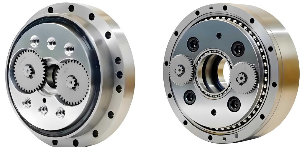
As shown, the RV reducer includes an input shaft (sun gear), spur gears, crank shafts, cycloidal gears, bearings, and housing. The transmission principle involves the sun gear driven by an external motor, which engages with the spur gears to produce the first-stage reduction. The spur gears then transfer torque to the crank shafts, actuating the cycloidal gears for the second-stage reduction. This multi-stage design allows for high reduction ratios in a compact form, but it also introduces dynamic challenges, particularly in the spur gear meshing interfaces. The modal analysis conducted here aims to address these challenges by evaluating the spur gear’s vibrational characteristics under realistic operating conditions.
To model the spur gear, I utilize a three-dimensional assembly based on an actual RV reducer model, specifically the RV-40E type. The gear material is set as 20CrMnTi steel, with material properties defined as density ρ = 7800 kg/m³, elastic modulus E = 2.07 × 10⁵ MPa, and Poisson’s ratio μ = 0.25. These parameters are critical for accurate finite element simulations. The gear geometry is meshed using hexahedral elements, with a global element size of 1 mm, resulting in a high-quality mesh suitable for modal analysis. For the meshing condition, the assembly includes the central gear and spur gears in contact, with constraints applied to simulate the actual transmission state, such as bonded contacts at the gear teeth interfaces and remote displacements to restrict axial and radial movements while allowing rotational degrees of freedom.
The theoretical foundation for modal analysis involves solving the eigenvalue problem derived from the equations of motion. For a linear system, the free vibration equation is given by:
$$ [M]\{\ddot{x}\} + [K]\{x\} = \{0\} $$
where [M] is the mass matrix, [K] is the stiffness matrix, and {x} is the displacement vector. By assuming harmonic motion, the natural frequencies and mode shapes can be obtained from:
$$ ([K] – \omega^2 [M])\{\phi\} = \{0\} $$
Here, ω represents the angular frequency, and {φ} is the mode shape vector. For the spur gear in an RV reducer, the stiffness matrix incorporates contributions from gear tooth contacts and support structures, making the analysis more complex under meshing conditions. I apply this formulation in the finite element software to compute the modal parameters for both free and constrained states.
In the free state, the spur gear is analyzed without any external constraints, allowing us to understand its inherent vibrational properties. The first ten natural frequencies and corresponding mode shapes are summarized in the table below. These results serve as a baseline for comparing the effects of meshing constraints in the RV reducer assembly.
| Mode Number | Frequency (Hz) | Mode Shape Description |
|---|---|---|
| 1 | 10868 | Second-order folding vibration |
| 2 | 17927 | Axial umbrella-shaped vibration |
| 3 | 24649 | Third-order folding vibration |
| 4 | 28907 | Radial symmetric vibration |
| 5 | 33719 | Axial torsional vibration |
| 6 | 39218 | Fourth-order folding vibration |
| 7 | 48165 | Radial twisting vibration |
| 8 | 49496 | Radial contraction vibration |
| 9 | 53851 | Fifth-order folding vibration |
| 10 | 57400 | Axial torsional vibration |
The mode shapes primarily exhibit deformations at the gear teeth, with symmetric patterns as the mode number increases. For instance, the first mode involves a second-order folding vibration where the gear teeth oscillate in a symmetrical manner, while higher modes show more complex torsional and radial motions. The natural frequencies range from approximately 10 kHz to 57 kHz, indicating a stiff structure in the free state. This high-frequency range is typical for precision gears used in RV reducers, but it may shift under operational constraints.
To delve deeper, the modal behavior can be related to gear geometry parameters. For a spur gear, the natural frequency for bending vibrations can be approximated using the formula:
$$ f_n = \frac{1}{2\pi} \sqrt{\frac{k_{eq}}{m_{eq}}} $$
where \( k_{eq} \) is the equivalent stiffness of the gear teeth and \( m_{eq} \) is the equivalent mass. In free state, the stiffness is dominated by the gear material and geometry, but in an RV reducer, additional stiffness from meshing contacts alters this relationship. The finite element model captures these effects by simulating the actual gear geometry with high mesh density at the teeth, ensuring accurate frequency predictions.
Under meshing conditions, the spur gear is integrated into the planetary transmission system of the RV reducer. The assembly includes the central gear and two spur gears, with constraints applied to replicate the actual working environment. The central gear is constrained to rotate only about its axis, while the spur gears are constrained by both the central gear teeth contacts and the crank shaft connections. This setup reflects the dynamic loading experienced during operation, where the spur gears transmit torque while undergoing complex vibrational excitations. The meshing state is analyzed at a critical engagement position where the contact ratio is minimal, to assess the worst-case vibrational response.
The results for the meshing state reveal significant changes in natural frequencies compared to the free state. The table below lists the first ten natural frequencies and mode shapes for the spur gear under meshing constraints in the RV reducer assembly.
| Mode Number | Frequency (Hz) | Mode Shape Description |
|---|---|---|
| 1 | 1277.6 | Mirrored torsional vibration on both sides |
| 2 | 5116.2 | Front-back swinging of spur gears on both sides |
| 3 | 5226.4 | Torsional vibration of spur gears on both sides |
| 4 | 5955.2 | Torsional and front-back vibration along the Z-axis |
| 5 | 6327.1 | Mirrored swinging along the Z-axis |
| 6 | 6357.8 | Folding vibration along the Z-axis |
| 7 | 6880.3 | Combined radial and axial vibration |
| 8 | 7012.9 | Asymmetric twisting of gear teeth |
| 9 | 7173.6 | Reverse bending vibration on both sides |
| 10 | 8320.5 | Same-direction bending vibration on both sides |
The frequencies in the meshing state are substantially lower, with values ranging from about 1.3 kHz to 8.3 kHz. This reduction is attributed to the added constraints from the central gear and crank shafts, which increase the system’s effective mass and alter the stiffness distribution. For example, the first mode at 1277.6 Hz involves a mirrored torsional vibration where the spur gears twist in opposite directions due to the symmetric constraints in the RV reducer. The mode shapes show that deformations are more pronounced in regions away from the meshing interfaces, indicating that the gear teeth near the central gear experience less displacement due to the restraining effects of contact forces.
The stiffness matrix in the meshing condition includes terms from gear tooth contacts, which can be modeled using Hertzian contact theory. The contact stiffness \( k_c \) between two gear teeth can be expressed as:
$$ k_c = \frac{\pi E L}{4(1-\mu^2)} \cdot \frac{1}{\ln\left(\frac{4R}{b}\right)} $$
where \( E \) is the elastic modulus, \( \mu \) is Poisson’s ratio, \( L \) is the tooth width, \( R \) is the effective radius of curvature, and \( b \) is the half-width of the contact area. In an RV reducer, multiple teeth are in simultaneous contact, leading to a complex stiffness network that lowers the overall natural frequencies. This effect is captured in the finite element model through bonded contact definitions at the meshing interfaces, simulating the stiffness contribution from the central gear.
Comparing the two states highlights the impact of assembly constraints on the dynamic behavior of the spur gear. In the free state, the gear exhibits high natural frequencies due to its isolated stiffness, but in the RV reducer, the interactions with other components reduce these frequencies significantly. This shift has practical implications for avoiding resonance in operational speed ranges. For instance, typical motor speeds in robotic applications can range from a few hundred to several thousand RPM, corresponding to frequencies up to 100 Hz or higher. The meshing state frequencies, while lower, are still above common excitation frequencies, but the reduction emphasizes the need for careful design to prevent resonant vibrations that could lead to fatigue or noise in the RV reducer.
Furthermore, the mode shapes under meshing conditions reveal that the spur gear’s weak points are near the teeth away from the central gear. The amplitude of vibration is higher in these regions, suggesting that stress concentrations may occur during operation. This insight is crucial for improving gear durability in RV reducers. By optimizing the gear profile or enhancing the material properties at these critical locations, one can mitigate potential failure modes such as tooth bending fatigue or pitting. Additionally, the constraints from the crank shafts introduce torsional modes, as seen in modes 3 and 4, which could affect the torque transmission efficiency of the RV reducer.
To quantify the frequency reduction, I calculate the ratio of meshing state frequencies to free state frequencies for corresponding modes. Although the mode orders do not directly align due to different constraint conditions, a general trend can be observed. For example, the first free mode at 10868 Hz drops to 1277.6 Hz in the meshing state, a reduction factor of approximately 8.5. This dramatic decrease underscores the softening effect of the RV reducer assembly. The relationship can be approximated by considering the added mass and stiffness from constraints. The effective natural frequency in a constrained system can be estimated as:
$$ f_{constrained} = \frac{1}{2\pi} \sqrt{\frac{k_{system}}{m_{system}}} $$
where \( k_{system} \) includes gear stiffness and contact stiffnesses, and \( m_{system} \) includes the gear mass and coupled masses from adjacent components. In the RV reducer, the crank shafts and central gear contribute to both parameters, leading to lower frequencies.
The analysis also considers the effects of damping, though in modal analysis, damping is often neglected for natural frequency extraction. However, in real RV reducer applications, material and structural damping play a role in vibration attenuation. The damping ratio \( \zeta \) can be incorporated into the dynamic equation:
$$ [M]\{\ddot{x}\} + [C]\{\dot{x}\} + [K]\{x\} = \{F\} $$
where [C] is the damping matrix. For steel gears, typical damping ratios are low (around 0.001-0.01), so the undamped assumption is valid for frequency predictions. Nevertheless, future studies could include damped analyses to evaluate vibration amplitudes under operational loads in RV reducers.
Another aspect is the influence of gear misalignment or assembly errors on modal characteristics. In precision RV reducers, even minor misalignments between the spur gear and central gear can alter contact patterns and stiffness, potentially shifting natural frequencies. The current model assumes perfect alignment, but in practice, tolerances must be accounted for. This highlights the importance of high-precision manufacturing and assembly processes for RV reducers to maintain consistent dynamic performance.
From a design perspective, the findings suggest several recommendations for improving RV reducer performance. First, the spur gear teeth should be reinforced near the root areas to reduce vibration amplitudes in meshing conditions. Second, the interface between the spur gear and crank shaft should be optimized to minimize additional constraints that might lower natural frequencies excessively. Third, material selection could be tailored to enhance stiffness without increasing mass, such as using advanced composites or surface treatments. These measures can help achieve a balance between high natural frequencies and operational reliability in RV reducers.
In conclusion, this modal analysis of the spur gear in an RV reducer under meshing conditions reveals significant changes in vibrational behavior compared to the free state. The constraints from the central gear and crank shafts reduce natural frequencies and alter mode shapes, with critical vibrations occurring at the gear teeth away from meshing interfaces. These insights are valuable for designing more robust and efficient RV reducers, particularly in high-demand applications like industrial robotics. By leveraging finite element simulations and theoretical models, engineers can better predict and mitigate dynamic issues, ultimately enhancing the longevity and precision of RV reducer systems.
Future work could extend this analysis to include transient dynamics or experimental validation. For instance, operating the RV reducer under load and measuring vibration responses could correlate with the simulated modes. Additionally, parameter studies on gear geometry or material properties could optimize the design for specific applications. As RV reducers continue to evolve, understanding their complex dynamics will remain a key area of research for advancing robotic technology.