
The precision and reliability of modern industrial robots are fundamentally dependent on the performance of their core transmission components. Among these, the Rotary Vector (RV) reducer is paramount, serving as the primary reduction unit in robotic joints. It is renowned for its compact size, high torsional stiffness, exceptional load capacity, and low backlash, making it ideally suited for high-precision applications. This study focuses on a critical aspect of RV reducer performance: its dynamic vibrational characteristics. Specifically, we investigate the modal properties of its core torque-transmitting element, the cycloidal gear. In practical operation, the excitation frequencies from servo motors can be complex and extend beyond simple rotational harmonics due to electromagnetic forces. Therefore, a comprehensive understanding of the natural frequencies and mode shapes of internal components is essential to avoid resonance, which can lead to excessive noise, accelerated wear, and failure. This paper presents a detailed finite element analysis (FEM) of the cycloidal gear under both free and constrained boundary conditions to identify its dynamic weaknesses and critical resonant frequencies, providing a theoretical foundation for optimizing the design and application of the rotary vector reducer.
Parametric Modeling and Finite Element Discretization of the Cycloidal Gear
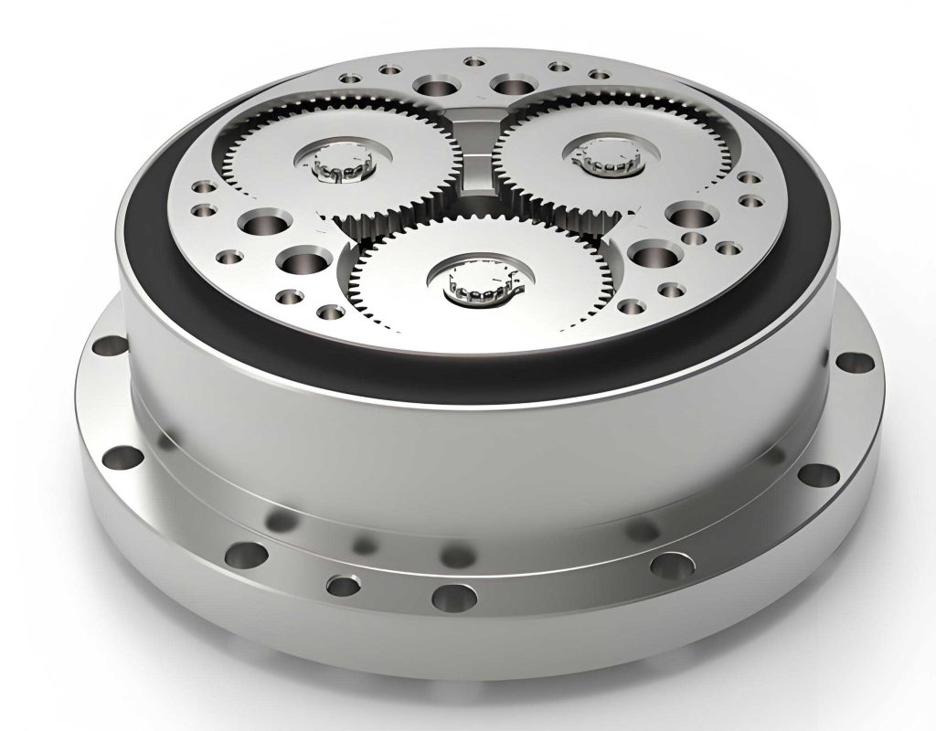
Our analysis is based on a widely used 2K-V type rotary vector reducer. The three-dimensional solid model of the cycloidal gear was created using a parametric approach. The primary technical parameters defining the gear’s geometry are summarized in the table below. These parameters are crucial for generating the precise tooth profile.
| Parameter Name | Symbol | Value |
|---|---|---|
| Number of Cycloidal Gear Teeth | \(Z_c\) | 41 |
| Number of Pin Gear Teeth | \(Z_p\) | 42 |
| Short Width Coefficient | \(K_1\) | 0.7 |
| Pin Gear Center Circle Radius | \(R_p\) | 108 mm |
| Tooth Width | \(B_c\) | 20 mm |
| Eccentricity | \(a\) | 2 mm |
| Pin Radius | \(r_{rp}\) | 5 mm |
The tooth profile of the cycloidal gear is governed by parametric equations derived from its rolling motion relative to the pin gear. The coordinates of the profile are given by:
$$x_0 = \left[R_p \left(1 – K_1 \cos(Z_p t)\right)\right] \sin\left(\frac{Z_p}{Z_c}t\right) – a \sin\left(\left(1-\frac{Z_p}{Z_c}\right)t\right)$$
$$y_0 = \left[R_p \left(1 – K_1 \cos(Z_p t)\right)\right] \cos\left(\frac{Z_p}{Z_c}t\right) – a \cos\left(\left(1-\frac{Z_p}{Z_c}\right)t\right)$$
where \(x_0\) and \(y_0\) are the Cartesian coordinates of the tooth profile, and \(t\) is the rolling motion parameter in radians. The model includes the central mounting hole for the output shaft (diameter 52 mm) and three smaller bearing bores (diameter 55 mm) equally spaced on a pitch circle diameter of 120 mm for the crankshaft bearings.
The material assigned to the cycloidal gear is bearing steel, with the following properties: Young’s Modulus \(E = 213\) GPa, Poisson’s ratio \(\mu = 0.292\), and density \(\rho = 7850\) kg/m³. The finite element mesh was generated using SOLID186 elements, a high-order 3D 20-node solid element well-suited for modeling complex geometries and deformation. The global mesh size was set to 2 mm, resulting in a high-quality mesh with 288,035 nodes and 64,130 elements. This mesh density ensures accurate calculation of the gear’s modal characteristics.
Finite Element Modal Analysis Methodology
To gain a comprehensive understanding of the dynamic behavior of the cycloidal gear within the rotary vector reducer, we performed two distinct types of modal analysis using the ANSYS finite element software: free modal analysis and constrained modal analysis. The subspace iteration method was employed to extract the eigenvalues (natural frequencies) and eigenvectors (mode shapes).
Free Modal Analysis: This analysis calculates the natural frequencies and mode shapes of the component without any external constraints. The first six modes in a free-free condition are rigid body modes (translational and rotational) with natural frequencies theoretically equal to zero, and are thus not considered in the dynamic assessment. We extracted and analyzed modes 7 through 20, which represent the gear’s elastic deformation modes.
Constrained Modal Analysis: This analysis simulates the gear’s operational condition. In the assembled rotary vector reducer, the cycloidal gear interacts with other components. The central hole is connected to the output shaft, and the three bearing bores are in contact with the crankshaft bearings. To approximate this, constraints were applied to the contact surfaces: the cylindrical surface of the central hole was fixed in the radial direction, and the cylindrical surfaces of the three bearing bores were fixed in both axial and radial directions, representing the constraint from the crankshaft bearings. This constrained model provides a more realistic representation of the gear’s dynamic response during service.
Analysis of Free Modal Results
The first 20 elastic natural frequencies and their corresponding maximum displacement magnitudes from the free modal analysis are listed in the table below. Neighboring modes, such as (7, 8), (9, 10), and (15, 16), exhibit very close or identical frequencies. This indicates they are repeated roots of the system’s vibration equation, representing mode pairs with similar frequencies but different spatial orientations.
| Mode Number | Natural Frequency (Hz) | Max Displacement (mm) |
|---|---|---|
| 7 | 1415.5 | 42.973 |
| 8 | 1415.5 | 42.473 |
| 9 | 2357.0 | 41.130 |
| 10 | 2357.0 | 29.776 |
| 11 | 3539.8 | 29.837 |
| 12 | 3539.9 | 38.606 |
| 13 | 3554.5 | 50.326 |
| 14 | 3648.7 | 32.136 |
| 15 | 4571.2 | 54.807 |
| 16 | 4875.8 | 54.474 |
| 17 | 4875.8 | 33.906 |
| 18 | 5782.0 | 33.873 |
| 19 | 5782.5 | 30.128 |
| 20 | 6309.3 | 43.701 |
Examination of the mode shapes reveals characteristic deformation patterns. For instance, in mode 7, the cycloidal gear exhibits bending deformation around the X-axis. Mode 9 shows significant axial (Z-direction) extension/contraction at the central hole. Mode 10 features deformation primarily in the Y-direction. Higher modes, such as 14 and 15, show complex coupling of bending and stretching at the thin webs connecting the central hub to the outer rim and bearing bores. The maximum displacements consistently occur at the tips of the cycloidal teeth or at the junctions between the holes and the gear body, highlighting these as structurally compliant areas in the free state.
Analysis of Constrained Modal Results and Comparative Study
The constrained modal analysis yields significantly different results, which are more relevant for the operational rotary vector reducer. The first 20 natural frequencies and maximum displacements under constraint are presented in the following table.
| Mode Number | Natural Frequency (Hz) | Max Displacement (mm) |
|---|---|---|
| 1 | 673.19 | 31.639 |
| 2 | 755.95 | 38.781 |
| 3 | 932.35 | 49.338 |
| 4 | 1489.7 | 52.747 |
| 5 | 1719.1 | 48.346 |
| 6 | 1733.2 | 53.723 |
| 7 | 2543.1 | 26.447 |
| 8 | 2786.5 | 29.979 |
| 9 | 3584.2 | 50.684 |
| 10 | 3671.2 | 45.222 |
| 11 | 3935.3 | 47.048 |
| 12 | 4679.8 | 43.171 |
| 13 | 4789.9 | 45.725 |
| 14 | 5110.8 | 50.063 |
| 15 | 6101.9 | 63.698 |
| 16 | 6241.9 | 42.082 |
| 17 | 6313.3 | 54.389 |
| 18 | 6448.6 | 55.408 |
| 19 | 6583.6 | 39.325 |
| 20 | 7332.1 | 40.661 |
A critical finding is that the natural frequencies in the constrained state are substantially lower than their counterparts in the free state for the lower-order modes. This is a direct consequence of the applied boundary conditions, which restrict deformation at the bearing and shaft interfaces, effectively reducing the overall stiffness of the structure for certain deformation patterns and causing the frequencies to shift downward. This underscores that free modal analysis alone cannot accurately predict the dynamic behavior of the cycloidal gear within the assembled rotary vector reducer.
The mode shapes under constraint also differ. The deformation remains concentrated in the cycloidal teeth and the thin ligaments between holes, but the specific patterns change. For example, the first mode (673.19 Hz) shows a combined bending of the outer rim. The third mode (932.35 Hz) involves significant bending at the outer rim and deformation at the output shaft hole interface. Notably, the maximum displacement in the constrained analysis often exceeds that of the free analysis for comparable mode orders, indicating higher dynamic stress concentrations under operating conditions. The most severe displacement (63.698 mm) occurs in the 15th constrained mode, located at a bearing bore junction.
Furthermore, a phenomenon of “mode crossing” is observed. For instance, the 17th constrained mode frequency (6313.3 Hz) is close to the 19th and 20th free mode frequencies. This indicates that the constraint conditions not only lower the frequencies but also reorder the modal sequence, making the dynamic response of the rotary vector reducer’s internal components more complex to predict without detailed constrained analysis.
Conclusion and Design Implications for the Rotary Vector Reducer
This detailed modal investigation of the cycloidal gear provides vital insights for the design and application of the rotary vector reducer. The analysis conclusively demonstrates that the constrained modal results, which reflect the gear’s installed state, are fundamentally different and more relevant than free modal results. Relying solely on free-free analysis for design validation would be insufficient and potentially misleading.
The most critical outcome is the identification of six primary natural frequencies in the low-to-mid frequency range (0-2000 Hz) under constrained conditions: 673.19 Hz, 755.95 Hz, 932.35 Hz, 1489.7 Hz, 1719.1 Hz, and 1733.2 Hz. These represent the modes most susceptible to excitation during operation. Therefore, during the design phase of the rotary vector reducer or the selection of a matching servo motor, the system’s excitation spectrum must be carefully managed to avoid these frequencies. This is crucial for preventing resonance, which can lead to excessive vibration, elevated noise levels, and premature fatigue failure of the cycloidal gear and other components.
Consistently, across both free and constrained analyses, the structural weak points of the cycloidal gear are identified as the tips of the cycloidal teeth and the thin webs connecting the central hub to the bearing bores and outer rim. These areas exhibit the largest deformations in most mode shapes. To enhance the dynamic performance and reliability of the rotary vector reducer, design optimization efforts should focus on increasing the localized stiffness in these regions, possibly through subtle geometric reinforcement or material selection, without significantly increasing inertia or weight.
In summary, this study establishes a foundational modal database for a key component of the rotary vector reducer. The findings offer a theoretical basis for dynamic design, vibration control, and noise reduction in high-precision RV reducers, contributing directly to the advancement of more reliable and high-performance industrial robotic systems.