
The evolution of robotics demands ever-higher performance from its core components, with the reduction gearbox being one of the most critical. This relentless drive for improvement compels engineers to enhance existing designs and pioneer novel transmission solutions. The cycloidal drive, specifically the RV (Rotary Vector) type used in robotic joints, represents a significant advancement in this field. Emerging from the foundation of traditional cycloidal pin-wheel planetary drives, the modern cycloidal drive overcomes many limitations of its predecessors. It is renowned for its compact size, light weight, exceptionally high reduction ratios, longevity, stable precision retention, high efficiency, and smooth operation. These attributes have garnered widespread international attention. In this detailed exploration, I will dissect the RV-type cycloidal drive, using a typical model as a reference. The focus will be on creating accurate 3D models of its key components, performing virtual assembly, and verifying kinematic relationships, with particular emphasis on the critical task of generating the correct cycloidal tooth profile.
Structural and Operational Principles of the RV Cycloidal Drive
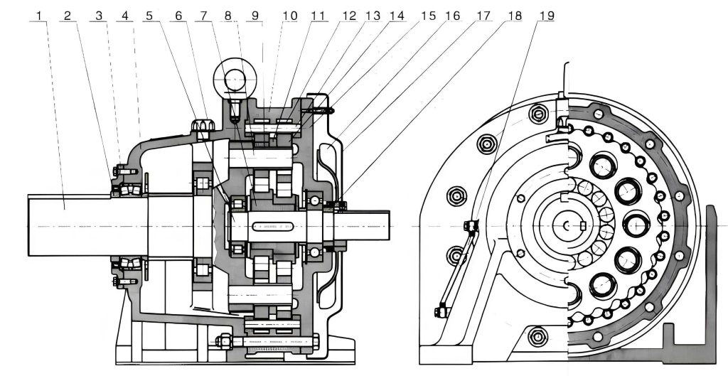
The RV-type cycloidal drive is a sophisticated two-stage, closed differential gear system. Its architecture seamlessly integrates two distinct planetary mechanisms into a single, highly rigid unit.
- First Stage – Planetary Gear Train: This stage consists of a sun gear (input), typically three planet gears arranged at 120°, and a fixed ring gear or a rotating carrier, depending on the design. The input rotation is provided to the sun gear.
- Second Stage – Cycloidal Pin-Wheel Drive: This is the heart of the cycloidal drive. The planet carrier from the first stage is not a simple output; instead, it is connected to eccentric crankshafts. Two cycloidal disks (lobed wheels), often offset by 180° to balance forces, are mounted on these cranks via needle roller bearings. These disks mesh with a stationary ring of cylindrical pins (the pin wheel).
The kinematic principle is elegant: The rotation from the first stage causes the eccentric crankshafts to orbit. This orbiting motion forces the cycloidal disks to undergo a compound movement—they both orbit around the center of the pin wheel and rotate on their own axes due to the sequential engagement with the stationary pins. The key is that this counter-rotation of the cycloidal disks is the desired output motion. An output flange, connected to the cycloidal disks through pins or holes, captures this slow rotation while filtering out the orbital component, resulting in a dramatically reduced output speed. The total reduction ratio itotal is the product of the ratios from both stages:
$$ i_{total} = i_{stage1} \times i_{stage2} $$
Where the second-stage ratio of a standard cycloidal drive is given by:
$$ i_{stage2} = \frac{Z_p}{Z_p – Z_c} $$
Here, $Z_p$ is the number of pins in the pin wheel, and $Z_c$ is the number of lobes on the cycloidal disk. Since $Z_p – Z_c$ is usually 1 or 2, this stage provides a very high reduction ratio.
Design and Parametric Modeling of Key Components
Accurate 3D modeling is the prerequisite for simulation, stress analysis, and digital prototyping. The critical components of an RV cycloidal drive include the input gear, the two-stage sun gear (center gear), planet gears, crankshafts, cycloidal disks, pin wheel housing, and the output flange. For this study, I will establish the geometric models based on the parameters of a representative model, RV-100E. Its primary specifications are summarized below.
| Parameter | Symbol | Value | Unit |
|---|---|---|---|
| Input Gear Teeth | $Z_1$ | 35 | – |
| Center Gear (Small) Teeth | $Z_2$ | 48 | – |
| Center Gear (Large) Teeth | $Z_3$ | 112 | – |
| Planet Gear Teeth | $Z_4$ | 33 | – |
| Cycloidal Disk Lobes | $Z_c$ | 51 | – |
| Pin Wheel Pins | $Z_p$ | 52 | – |
| Pressure Angle (Gears) | $\alpha$ | 20 | ° |
| Pin Circle Radius | $r_p$ | 102 | mm |
| Pin Radius | $r_{rp}$ | 3 | mm |
| Crank Eccentricity | $e$ | 1.5 | mm |
| Planet Gear Width | $B_4$ | 7 | mm |
| Cycloidal Disk Width | $B_c$ | 11.5 | mm |
Modeling the Heart: The Cycloidal Disk
The cycloidal disk is the defining component of the cycloidal drive. Its complex lobe profile dictates the drive’s performance, smoothness, and load distribution. While the disk itself is a plate-like structure with mounting holes, the core challenge lies in accurately generating its tooth flank curve. Since standard CAD software like SolidWorks lacks a direct “cycloid” sketch tool, we must rely on its parametric or data import capabilities.
The standard tooth profile for a cycloidal disk meshing with a pin wheel is derived from the rolling of one circle (generating circle) around another (base circle), with the trace of a point on the rolling circle’s circumference forming an epicycloid or hypotrochoid. Accounting for pin radius (to create a equidistant curve) and the required backlash, the modified profile in parametric form (with parameter $t$, typically in radians) is:
$$
\begin{aligned}
x(t) &= \left[ r_p \sin\left(\frac{t}{Z_c}\right) – e \sin\left(\frac{Z_p}{Z_c}t\right) \right] + r_{rp} \cdot \frac{ \frac{Z_p e}{r_p} \sin\left(\frac{Z_p}{Z_c}t\right) – \sin\left(\frac{t}{Z_c}\right) }{K(t)} \\
y(t) &= \left[ r_p \cos\left(\frac{t}{Z_c}\right) – e \cos\left(\frac{Z_p}{Z_c}t\right) \right] + r_{rp} \cdot \frac{ \frac{Z_p e}{r_p} \cos\left(\frac{Z_p}{Z_c}t\right) – \cos\left(\frac{t}{Z_c}\right) }{K(t)} \\
K(t) &= \sqrt{1 + \left(\frac{Z_p e}{r_p}\right)^2 – 2\left(\frac{Z_p e}{r_p}\right)\cos(t)}
\end{aligned}
$$
Here, $r_p$, $e$, $r_{rp}$, $Z_p$, and $Z_c$ are as defined in Table 1. Based on these equations, I have successfully implemented two robust modeling methodologies within SolidWorks.
| Method | Process Description | Advantages | Considerations |
|---|---|---|---|
| 1. External Data Import (Point Cloud) |
|
|
|
| 2. Native Equation-Driven Curve |
|
|
|
For my modeling process, I primarily employed the second method—the native equation-driven curve. This approach provides a seamless parametric link between the design parameters and the final geometry, which is invaluable for exploring design variations of the cycloidal drive. Once a single lobe is generated, the sketch is extruded to the defined width $B_c$, and the central bearing bore and mounting pin holes are added to complete the cycloidal disk model.
Modeling Supporting Components
While the cycloidal disk is the most complex part, other components are essential for a complete cycloidal drive assembly.
- Gears (Input, Center, Planets): For the involute spur gears of the first stage, I utilized a dedicated gear plugin (e.g., GearTrax). This tool allows for rapid generation of standard and custom gears by simply inputting basic parameters like module, number of teeth, pressure angle, and face width. The plugin generates a fully-featured SolidWorks part, including the correct tooth profile and root geometry, which can then be modified as needed.
- Crankshafts: These are machined shafts with eccentric journals. Their modeling involves creating revolved base features for the main shaft and journals, then using the “Offset from Surface” or a similar technique to create the eccentric sections. Keyways or splines for connecting to the planet gears are added using standard cut features.
- Pin Wheel Housing: This component contains the precision-machined holes for the press-fit pins. It is typically modeled as a circular housing with a bolt pattern. The pin holes are located on the pitch circle radius $r_p$ and patterned $Z_p$ times.
- Bearings: The cycloidal drive uses various specialized bearings (needle roller bearings on the crank journals, angular contact ball bearings for thrust loads, tapered roller bearings for radial support). Simplified bearing models are often sufficient for assembly and interference checking, created as sub-assemblies of inner ring, outer ring, and rolling elements with appropriate mating conditions.
Virtual Assembly and Kinematic Verification
With all component models created, the next critical phase is the virtual assembly. I adopt a bottom-up approach, building sub-assemblies first and then integrating them into the final product assembly. This hierarchical method simplifies the management of mating relationships, especially in a complex system like a cycloidal drive.
Sub-Assembly Construction
Building logical sub-assemblies is crucial for organization and reusability.
- Bearing Sub-Assemblies: Each bearing type is assembled separately. For example, a tapered roller bearing sub-assembly is created by mating the rollers tangentially to the inner and outer raceways and axially positioning them with the cage.
- Crankshaft Sub-Assembly: Each crankshaft is assembled with its two needle roller bearing sets on the eccentric journals and the two supporting tapered roller bearings on the main journals. Locking plates or nuts are also added.
- Pin Wheel Sub-Assembly: The cylindrical pins (rollers) are inserted into the pin wheel housing holes using concentric and coincident mates, then circularly patterned.
Master Assembly Procedure
The final assembly of the RV cycloidal drive follows a logical sequence that mirrors the physical assembly process. The core kinematic relationships are established through specific mates.
| Step | Component(s) Added | Primary Mates Applied | Kinematic Purpose |
|---|---|---|---|
| 1 | Output Flange, Main Bearings, Pin Wheel | Concentric (axes), Coincident (faces) | Establishes the fixed reference frame for the second stage (pin wheel stationary relative to output housing). |
| 2 | Crankshaft Sub-Assemblies (x3) | Tapered bearing outer races mated to output flange holes (Concentric, Coincident). | Positions the three crankshafts at 120°, allowing them to rotate within the output flange. |
| 3 | Cycloidal Disks (x2, 180° offset) | Needle rollers on cranks mated tangentially to disk bore surfaces. Disks also mated concentrically to each other. | Connects disks to eccentric cranks. The tangential mate allows the disks to rotate freely on the cranks while being driven by the eccentricity. |
| 4 | Input Flange & Bearings | Mated to crankshaft ends and main housing. | Completes the support structure and provides the input connection. |
| 5 | Planet Gears (x3) | Gear mates with the large center gear. Concentric/concentric mates with crankshaft splines. | Creates the first-stage planetary reduction. The gear mate defines the speed ratio between sun and planets. |
| 6 | Center (Sun) Gear | Gear mates with planets. Supported by bearing in input flange. | Completes the first stage. Rotating the sun gear drives the entire mechanism. |
| 7 | Output Pins & Cycloidal Disk Holes | Concentric mates between output pins (on flange) and holes in cycloidal disks. | This is the output mechanism. It filters the rotation of the cycloidal disks, transferring only their slow, counter-rotational motion to the output flange. |
The final check involves using SolidWorks’ interference detection tool to ensure no unintended physical clashes exist. More importantly, applying the “Move Component” or “Physical Dynamics” tool to rotate the input sun gear should result in the slow, steady rotation of the output flange, visually confirming the massive reduction ratio and the correct kinematic function of the cycloidal drive. The theoretical reduction ratio can be calculated and compared against the observed motion for verification.
For the RV-100E with $Z_1$=35, $Z_3$=112, $Z_4$=33, $Z_c$=51, $Z_p$=52, the ratio is:
$$ i_{stage1} = 1 + \frac{Z_3}{Z_1} = 1 + \frac{112}{35} = 4.2 $$
$$ i_{stage2} = \frac{Z_p}{Z_p – Z_c} = \frac{52}{52 – 51} = 52 $$
$$ i_{total} = i_{stage1} \times i_{stage2} = 4.2 \times 52 = 218.4 $$
This means approximately 218.4 input revolutions yield one output revolution.
Exploded View and Animation for Communication
To effectively communicate the assembly sequence and spatial relationships within the complex cycloidal drive, creating an exploded view is essential. In SolidWorks, this involves defining explode steps along appropriate axes (often the main drive axis). Each step logically separates a component or sub-assembly, ideally following the reverse of the assembly sequence for clarity in disassembly instructions. The resulting view provides an invaluable aid for manufacturing, maintenance, and technical documentation. Furthermore, this exploded configuration can be animated using SolidWorks’ Animation wizard, creating a dynamic video (e.g., AVI format) that clearly demonstrates how all components—from the input pinion to the output flange, including the critically interacting cycloidal disks and pins—come together to form the complete, functional cycloidal drive unit.
Conclusion and Further Applications
The meticulous process of 3D modeling and virtual assembly for an RV cycloidal drive is far more than an academic exercise. It serves as the foundational step for advanced engineering analysis and product development. The accurate parametric model of the cycloidal disk, enabled by the direct input of its governing equations, allows for subsequent Finite Element Analysis (FEA) to evaluate stress concentrations and optimize lobe geometry for load capacity. The complete digital twin of the assembly facilitates dynamic simulation to assess vibration, calculate precise torsional stiffness, and verify bearing life under load spectra. Furthermore, this model is directly usable for generating CNC machining paths for prototypes or for creating realistic renderings for marketing. Mastering the generation of the cycloidal profile and understanding the intricate mating relationships within the assembly are therefore critical competencies for any engineer working on the design, application, or innovation of this high-performance cycloidal drive technology, which continues to be a cornerstone of precision motion control in robotics and automation.