
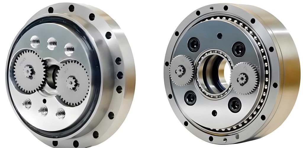
In modern industrial automation, the rotary vector reducer plays a pivotal role in robotic systems, ensuring precision motion control and high torque transmission. As a core component of the rotary vector reducer, the planetary carrier requires stringent dimensional accuracy, particularly for its circumferential holes, which directly impact assembly quality and operational performance. Traditional measurement methods, such as manual gauging or offline coordinate measuring machines, often fall short in production line environments due to time constraints and environmental variability. Therefore, developing an online automatic measurement system is crucial for real-time quality assurance. This article presents a comprehensive study on an online automatic aperture measurement instrument based on differential pressure pneumatic technology, tailored for the planetary carrier of the rotary vector reducer. I will delve into the measurement principles, system design, error analysis, and experimental validation, emphasizing the integration of pneumatic, mechanical, and electrical modules to achieve high accuracy and efficiency. Throughout this discussion, the term “rotary vector reducer” will be frequently highlighted to underscore its relevance in industrial applications.
The planetary carrier, as part of the rotary vector reducer, features multiple circumferentially distributed holes that must adhere to tight tolerances, typically within micrometers. These holes accommodate bearings and eccentric shafts, and any deviation can lead to uneven load distribution, reduced transmission stability, and premature wear. Consequently, full inspection is necessary to eliminate defective parts and maintain the integrity of the rotary vector reducer. However, existing measurement techniques, including contact methods like plug gauges or non-contact optical systems, often lack the speed and robustness required for online implementation. Pneumatic measurement, with its non-contact nature and immunity to environmental disturbances, offers a promising solution. This article explores a differential pressure pneumatic approach, enabling automated, real-time data acquisition with minimal human intervention, specifically designed for the rotary vector reducer’s planetary carrier.
The measurement principle relies on the linear relationship between air pressure and the gap between a pneumatic probe and the hole wall. In differential pressure pneumatic measurement, compressed air is regulated to a constant pressure and directed through a nozzle into a cavity formed by the probe and the workpiece. As the gap changes, the backpressure varies proportionally, which is detected by a differential pressure sensor. This relationship can be expressed mathematically as:
$$d = k \cdot p + b$$
where \(d\) represents the hole diameter, \(p\) is the measured pressure value, and \(k\) and \(b\) are linear coefficients determined through calibration. For the rotary vector reducer’s planetary carrier, a dual-section eight-nozzle pneumatic probe is designed to measure both upper and lower holes simultaneously, ensuring comprehensive assessment. Calibration involves using two master rings with known diameters, denoted as \(d_{\text{max}}\) and \(d_{\text{min}}\), to establish the linear parameters. The calibration equation is:
$$
\begin{bmatrix}
k & 0 \\
0 & k
\end{bmatrix}
\begin{bmatrix}
p_1 & 0 \\
0 & p_2
\end{bmatrix}
+
\begin{bmatrix}
b & 0 \\
0 & b
\end{bmatrix}
=
\begin{bmatrix}
d_{\text{max}} & 0 \\
0 & d_{\text{min}}
\end{bmatrix}
$$
where \(p_1\) and \(p_2\) are the pressure values for the upper and lower master rings, respectively. This comparative measurement scheme enhances accuracy by compensating for system drift, making it ideal for the high-precision demands of the rotary vector reducer.
The system design is modular, incorporating pneumatic, mechanical, and electrical subsystems. The pneumatic system includes the dual-section eight-nozzle probe, which features four nozzles per section arranged orthogonally to measure diameters in two perpendicular directions. Each pair of opposing nozzles shares a pneumatic circuit, resulting in four independent circuits for comprehensive data acquisition. The nozzles are circular to ensure linear response within the measurement range. The mechanical system comprises a linear motion mechanism and a precision rotary mechanism. The linear mechanism uses a pneumatic cylinder and guide rails to vertically position the probe, while a floating unit prevents rigid collisions with the hole walls, allowing radial displacement up to 1 mm. The rotary mechanism, driven by a servo motor with a circular grating feedback, rotates the planetary carrier to align each circumferential hole for measurement. This setup ensures that the probe axis is tangent to the hole’s reference circle, facilitating safe entry and accurate measurement for the rotary vector reducer components.
The electrical system integrates a industrial computer, motion control cards, data acquisition cards, and signal conditioning units. It operates on a bus-based architecture, where the main control module sends commands to motion control and data acquisition modules. The motion control module governs the servo motor and cylinder actions, while the data acquisition module processes sensor signals from the pneumatic probe. Real-time data collection and processing are achieved through customized software, enabling automated measurement cycles within 30 seconds per part. This efficiency is critical for production lines involving the rotary vector reducer, where throughput and precision must be balanced.
Error analysis is essential to ensure measurement reliability. Structural errors arise from misalignment between the probe and hole axes, including translation and tilt. For translation, the maximum error occurs when the probe axis is offset by a distance \(S\), derived from the difference between the hole diameter \(D\) and probe diameter \(d\). The error \(\delta_1\) for one extreme position is:
$$\delta_1 = \frac{D – \sqrt{D^2 – (D – d)^2}}{2}$$
and for another position, \(\delta_2\) is:
$$\delta_2 = D – \sqrt{D^2 – 2(D – d)^2}$$
Given the planetary carrier hole tolerance of \(\Phi58^{+0.004}_{-0.004}\) mm and probe diameter of \(\Phi57.996^{-0.010}_{-0.015}\) mm, these errors are negligible (e.g., \(\delta_2 \approx 0.00912 \mu m\)). For tilt error \(\delta_3\), when the probe axis is inclined by an angle \(\theta\), it can be approximated as:
$$\delta_3 \approx D \frac{\theta^2}{2}$$
where \(\theta \approx \tan \theta = \frac{S}{H}\), with \(H\) as the hole depth. For \(H = 98.3\) mm, \(\delta_3\) is about 0.156 \(\mu m\). Environmental temperature effects also introduce error due to thermal expansion of the planetary carrier material (GCr15 steel, coefficient \(\alpha \approx 1.4 \times 10^{-5} /^\circ\text{C}\)). The diameter change \(\Delta d\) for a temperature variation \(\Delta T\) is calculated from volume conservation:
$$\Delta d = \sqrt{\frac{D_0^2 (1 + \alpha \Delta T)^2 – D_0^2 (1 + 3\alpha \Delta T) + d_0^2 (3 + 9\alpha \Delta T)}{3}} – d_0$$
where \(D_0\) and \(d_0\) are initial outer and inner diameters. For \(\Delta T = 1^\circ\text{C}\), \(\Delta d \approx 0.39 \mu m\). These errors are summarized in the table below, highlighting their minimal impact on the rotary vector reducer measurement system.
| Error Source | Symbol | Maximum Error (μm) | Notes |
|---|---|---|---|
| Probe Translation | δ₁, δ₂ | < 0.01 | Negligible for rotary vector reducer |
| Probe Tilt | δ₃ | 0.156 | Based on geometry |
| Temperature Effect | Δd | 0.39 | For ΔT = 1°C |
Experimental validation was conducted in a controlled production line environment at 20±1°C and 61% humidity. The measurement instrument was first calibrated using master rings, then tested on a planetary carrier from a rotary vector reducer. Repeatability tests involved 30 consecutive measurements on three circumferential holes (I, II, III) for both upper and lower sections. Results were compared with reference values from a high-precision coordinate measuring machine (Leitz Infinity). The data, presented in the table below, demonstrate excellent repeatability and accuracy.
| Hole Section | Hole Number | Reference Diameter (mm) | Mean Measured Diameter (mm) | Standard Deviation (μm) | Error (μm) |
|---|---|---|---|---|---|
| Upper | I | 58.0010 | 57.9997 | 0.13 | -1.3 |
| II | 58.0012 | 58.0003 | 0.15 | -0.9 | |
| III | 58.0000 | 57.9997 | 0.12 | -0.3 | |
| Lower | I | 58.0003 | 58.0011 | 0.18 | 0.8 |
| II | 58.0028 | 58.0027 | 0.22 | -0.1 | |
| III | 58.0020 | 58.0015 | 0.20 | -0.5 |
The repeatability standard deviation is below 0.22 μm, and the measurement error is within 1.3 μm, confirming the system’s suitability for the rotary vector reducer’s precision requirements. Uncertainty evaluation according to JJF 1059-2012 considers multiple sources: repeatability (\(u_a\)), instrument calibration (\(u_{b1}\)), probe structure (\(u_{b2}\)), and temperature effects (\(u_{b3}\)). Using a uniform distribution for systematic errors, the contributions are:
$$u_a = \frac{s}{\sqrt{n}} = \frac{0.22}{\sqrt{29}} \approx 0.041 \mu m$$
$$u_{b1} = \frac{0.5}{\sqrt{3}} \approx 0.29 \mu m$$
$$u_{b2} = \frac{0.156}{\sqrt{12}} \approx 0.045 \mu m$$
$$u_{b3} = \frac{0.39}{\sqrt{3}} \approx 0.23 \mu m$$
The combined standard uncertainty is:
$$u_c = \sqrt{u_a^2 + u_{b1}^2 + u_{b2}^2 + u_{b3}^2} \approx 0.38 \mu m$$
With a coverage factor \(k=2\), the expanded uncertainty is \(U = k u_c \approx 0.8 \mu m\). This low uncertainty underscores the instrument’s capability for high-precision online measurement in rotary vector reducer manufacturing.
In conclusion, the developed online automatic aperture measurement instrument based on differential pressure pneumatic technology effectively addresses the challenges of measuring planetary carrier holes in the rotary vector reducer. By integrating a dual-section eight-nozzle probe, modular motion mechanisms, and real-time data acquisition, it achieves a measurement cycle under 30 seconds with repeatability below 0.22 μm and error within 1.3 μm. The error analysis and uncertainty evaluation confirm robustness against structural and environmental influences. This system not only enhances production efficiency but also ensures quality control for the rotary vector reducer, contributing to the advancement of industrial robotics. Future work could explore adaptive calibration techniques or integration with artificial intelligence for predictive maintenance, further optimizing the performance of rotary vector reducers in automated systems.
Throughout this research, the importance of the rotary vector reducer in industrial applications has been emphasized, and the measurement technology presented here offers a reliable solution for maintaining its precision. By leveraging pneumatic principles and automated design, this instrument sets a benchmark for online dimensional metrology, paving the way for smarter manufacturing processes centered on the rotary vector reducer.