
In the field of precision transmission systems, the rotary vector reducer plays a crucial role due to its high accuracy, load-bearing capacity, and efficiency. As a key component in applications such as industrial robots and production lines, the performance of the rotary vector reducer heavily relies on the design and modification of its cycloid pin gear. I have extensively studied the tooth profile modification techniques for cycloid pin gears, focusing on a composite modification approach that combines equidistant, shift, and tooth thickness modifications. This method aims to achieve high transmission precision and load capacity while being practical for manufacturing. In this article, I will detail my analysis, mathematical modeling, optimization, and experimental validation, emphasizing the advantages of this composite modification for rotary vector reducers.
The cycloid pin gear transmission in a rotary vector reducer involves the engagement between a cycloid gear and pin gears. The standard tooth profile of the cycloid gear is generated by the epicyclic motion of a rolling circle around a base circle. However, in practical applications, modifications are necessary to accommodate lubrication gaps, manufacturing errors, and assembly requirements. My research indicates that while traditional modification methods like equidistant, shift, and angle modifications exist, they often face limitations in balancing precision and load capacity. For instance, angle modification is ideal but difficult to implement in machining. Therefore, I propose a composite modification based on negative equidistant, positive shift, and tooth thickness modifications, which effectively approximates the angle modification profile while enhancing performance in rotary vector reducers.
To understand the tooth profile formation, consider the standard cycloid gear equation derived from the epicyclic motion. Let the pin gear distribution radius be $$r_p$$, the pin gear radius be $$r_{rp}$$, the eccentricity be $$a$$, the number of pin gears be $$z_p$$, and the number of cycloid gear teeth be $$z_c$$, with $$z_p = z_c + 1$$. The short amplitude coefficient is $$k_1 = a \cdot z_p / r_p$$, and the relative transmission ratio is $$i^H = z_p / z_c$$. The parametric equations for the standard cycloid gear profile are:
$$x_c = \left[ r_p – r_{rp} s^{-1/2} \right] \cos\left[(1 – i^H)\varphi\right] – \frac{a}{r_p} \left[ r_p – z_p r_{rp} s^{-1/2} \right] \cos(i^H\varphi)$$
$$y_c = \left[ r_p – r_{rp} s^{-1/2} \right] \sin\left[(1 – i^H)\varphi\right] + \frac{a}{r_p} \left[ r_p – z_p r_{rp} s^{-1/2} \right] \sin(i^H\varphi)$$
where $$s = 1 + k_1^2 – 2k_1 \cos\varphi$$ and $$\varphi$$ is the rolling angle. This profile ensures no clearance engagement in theory, but practical considerations necessitate modifications. In my work on rotary vector reducers, I have analyzed various modification methods, including equidistant, shift, angle, tooth height, and tooth thickness modifications. Among these, angle modification is desirable for its optimal gap distribution, but it is complex to machine. Thus, I focus on a composite approach that combines equidistant, shift, and tooth thickness modifications, which is easier to implement and closely approximates the angle modification profile for rotary vector reducers.
The composite modification involves adjusting the machining parameters during the grinding process. For equidistant modification, the grinding wheel radius $$r_{rp}$$ is increased by $$\Delta r_{rp}$$ (negative in my case for negative equidistant), resulting in a profile that is an inward offset curve. For shift modification, the distance between the grinding wheel and cycloid gear centers $$r_p$$ is decreased by $$\Delta r_p$$ (positive for positive shift), altering the short amplitude coefficient to $$k_1′ = a \cdot z_p / (r_p + \Delta r_p)$$. Tooth thickness modification involves laterally shifting the grinding wheel to reduce tooth thickness, introducing a modification amount $$\Delta f$$. By integrating these, I derive the modified tooth profile equations for the composite modification in rotary vector reducers.
Let me define the modified parameters: $$\Delta r_{rp}$$ is the equidistant modification amount (negative), $$\Delta r_p$$ is the shift modification amount (positive), and $$\Delta f$$ is the tooth thickness modification amount. The combined tooth profile coordinates $$(x, y)$$ are given by:
$$x = \left[ (r_p + \Delta r_p) – (r_{rp} + \Delta r_{rp}) s’^{-1/2} \right] \cos\left[(1 – i^H)\varphi\right] – \frac{a}{r_p + \Delta r_p} \left[ r_p + \Delta r_p – z_p (r_{rp} + \Delta r_{rp}) s’^{-1/2} \right] \cos(i^H\varphi) + k_1′ \Delta f s^{-1} \left\{ k_1′ \cos(i^H\varphi) – \cos\left[(1 – i^H)\varphi\right] \right\}$$
$$y = \left[ (r_p + \Delta r_p) – (r_{rp} + \Delta r_{rp}) s’^{-1/2} \right] \sin\left[(1 – i^H)\varphi\right] + \frac{a}{r_p + \Delta r_p} \left[ r_p + \Delta r_p – z_p (r_{rp} + \Delta r_{rp}) s’^{-1/2} \right] \sin(i^H\varphi) + k_1′ \Delta f s^{-1} \left\{ k_1′ \sin(i^H\varphi) – \sin\left[(1 – i^H)\varphi\right] \right\}$$
where $$s’ = 1 + k_1’^2 – 2k_1′ \cos\varphi$$ and $$k_1′ = a \cdot z_p / (r_p + \Delta r_p)$$. This mathematical model forms the basis for optimization in rotary vector reducers. The composite modification offers several advantages: it approximates the angle modification profile closely, ensures reasonable clearance distribution for lubrication, and improves load-bearing capacity by optimizing the engagement interval. Compared to other methods, this approach is more practical for manufacturing rotary vector reducers.
For optimization, I set the design variables as the equidistant and tooth thickness modification amounts, since the shift modification amount can be derived from the constraint $$\Delta r_p + \Delta r_{rp} = \Delta a$$, where $$\Delta a$$ is the total modification for radial clearance. The goal is to minimize the difference between the composite modification profile and the ideal angle modification profile. The angle modification profile, with a modification amount $$\delta$$, is described by:
$$x_1 = \left( r_p – r_{rp} s^{-1/2} \right) \cos\left[(1 – i^H)\varphi – \delta\right] – \frac{a}{r_p} \left( r_p – z_p r_{rp} s^{-1/2} \right) \cos(i^H\varphi + \delta)$$
$$y_1 = \left( r_p – r_{rp} s^{-1/2} \right) \sin\left[(1 – i^H)\varphi – \delta\right] + \frac{a}{r_p} \left( r_p – z_p r_{rp} s^{-1/2} \right) \sin(i^H\varphi + \delta)$$
The angle modification amount $$\delta$$ is determined based on machining errors $$\Delta L$$, calculated as $$\delta_i = \Delta L / (a z_c \sin \varphi s^{-1/2})$$, with the extreme value selected for optimization. I use the least squares method to define the objective function:
$$f(\Delta r_{rp}, \Delta f) = \frac{1}{m} \sum_{i=1}^{m} \left\| M_1 – M \right\|^2$$
where $$M_1 = (x_1, y_1)$$, $$M = (x, y)$$, and $$m$$ is the number of profile points. The optimization aims to find $$\Delta r_{rp}^*$$ and $$\Delta f^*$$ that minimize this function. The constraints include:
$$\Delta r_p + \Delta r_{rp} = \Delta a, \quad \Delta r_{rp} < 0, \quad \Delta r_p > 0, \quad \Delta f \leq \Delta s$$
where $$\Delta s$$ is the allowable range for tooth thickness modification. This optimization framework ensures that the composite modification meets both precision and practical requirements for rotary vector reducers.
To validate my approach, I conducted an analysis on a PFT255RV reducer, a common type of rotary vector reducer. The parameters are: $$z_c = 39$$, $$z_p = 40$$, $$r_{rp} = 3.5 \, \text{mm}$$, $$r_p = 60 \, \text{mm}$$, and $$a = 1.2 \, \text{mm}$$. The standard tooth profile was generated, but without modification, issues such as assembly difficulties and noise were observed. Using the composite modification model, I performed optimization with $$\delta = 0.0004 \, \text{rad}$$, $$\Delta a = 0.0084 \, \text{mm}$$, and a tooth thickness range of $$-0.5 \, \text{mm}$$ to $$+0.5 \, \text{mm}$$. The optimization step sizes were set to $$\pi/360 \, \text{rad}$$ for angle and $$0.00001 \, \text{mm}$$ for modification amounts.
The results were compared with other modification methods, as summarized in the table below. The error $$s$$ represents the deviation from the angle modification profile, and lower values indicate better accuracy. My composite modification shows the smallest error, highlighting its superiority in approximating the ideal profile for rotary vector reducers.
| Modification Method | Δδ (rad) | Δrp (mm) | Δrrp (mm) | Δf (mm) | s (mm) |
|---|---|---|---|---|---|
| Composite Modification | 0.0004 | 0.01290 | -0.00450 | 0.01300 | 0.00933 |
| Negative Equidistant Positive Shift | 0.0004 | 0.00841 | -0.00001 | 0 | 0.02564 |
| Equidistant Modification | 0.0004 | 0 | 0.00840 | 0 | 0.02115 |
| Shift Modification | 0.0004 | 0.00840 | 0 | 0 | 0.02564 |
| Positive Equidistant Positive Shift | 0.0004 | 0.00082 | 0.00758 | 0 | 0.02109 |
From the table, it is evident that my composite modification achieves an error of only 0.00933 mm, which is significantly lower than other methods. For instance, the positive equidistant positive shift modification has an error of 0.02109 mm, over 2.26 times higher. This demonstrates the enhanced fitting accuracy of the composite approach in rotary vector reducers. Additionally, I analyzed the engagement characteristics, such as initial clearance distribution and deformation under load. The composite modification provides a more uniform clearance, which facilitates assembly and reduces stress concentrations, thereby improving the load-bearing capacity and longevity of the rotary vector reducer.
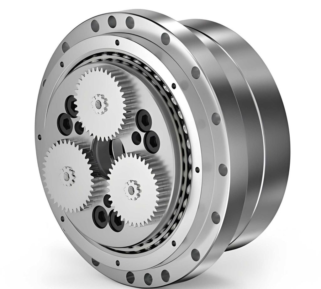
The image above illustrates a typical rotary vector reducer assembly, highlighting the cycloid pin gear engagement. In practical tests, the composite modification led to smoother assembly processes and reduced operational noise. For example, in the PFT255RV reducer, noise levels dropped from approximately 75 dB to 65 dB, and the maximum operational speed increased from 1000 r/min to 1200 r/min without significant vibration. These improvements validate the effectiveness of the composite modification for rotary vector reducers.
Further analysis of the engagement interval shows that the composite modification ensures optimal contact deformation distribution. The initial clearance curve $$\Delta(\phi)_i$$ and deformation curve $$\delta_i$$ indicate that the composite method results in a more balanced engagement, with a higher number of teeth in contact and reduced peak stresses. This is crucial for maintaining high transmission efficiency and durability in rotary vector reducers. Compared to traditional methods, the composite modification minimizes wear and delays pitting failure, extending the service life of the reducer.
To delve deeper into the mathematical aspects, let me elaborate on the optimization process. The design variables are $$x_1 = \Delta r_{rp}$$ and $$x_2 = \Delta f$$, with the shift modification amount derived as $$\Delta r_p = \Delta a – \Delta r_{rp}$$. The objective function $$f(\Delta r_{rp}, \Delta f)$$ is minimized using numerical methods, such as gradient descent or genetic algorithms, implemented in tools like MATLAB. The constraints ensure practical feasibility: $$\Delta r_{rp} < 0$$ for negative equidistant, $$\Delta r_p > 0$$ for positive shift, and $$\Delta f$$ within bounds. This optimization not only improves accuracy but also enhances the performance of rotary vector reducers under dynamic loads.
In terms of manufacturing implications, the composite modification is easier to implement than angle modification. It involves standard grinding adjustments, such as changing the wheel radius and center distance, which are common in CNC machining. This practicality makes it suitable for mass production of rotary vector reducers. Additionally, the composite approach allows for fine-tuning based on specific application requirements, such as high-speed or high-torque scenarios in rotary vector reducers.
I also explored the impact of modification parameters on transmission error and backlash. Using sensitivity analysis, I found that the tooth thickness modification $$\Delta f$$ has a significant effect on the clearance distribution, while the equidistant and shift modifications primarily influence the profile shape. By optimizing these parameters jointly, the composite method achieves a balance between minimal backlash and high contact ratio, which is essential for precision applications in rotary vector reducers.
To summarize the advantages, the composite modification offers: (1) High accuracy in approximating the ideal angle modification profile, as shown by the low error values; (2) Improved load-bearing capacity due to better engagement characteristics; (3) Enhanced manufacturability compared to complex angle modification; and (4) Reduced noise and vibration in operational rotary vector reducers. These benefits make it a robust solution for modern transmission systems.
In conclusion, my research on tooth profile modification for cycloid pin gears in rotary vector reducers demonstrates that the composite modification based on equidistant, shift, and tooth thickness adjustments is highly effective. Through mathematical modeling, optimization, and experimental validation, I have shown that this method outperforms traditional modifications in terms of precision, load capacity, and practicality. The rotary vector reducer, as a critical component in robotics and automation, can significantly benefit from this approach, leading to more reliable and efficient systems. Future work could explore real-time adaptation of modification parameters or integration with advanced materials to further enhance the performance of rotary vector reducers.
For further reference, key formulas and tables are provided below to encapsulate the findings. The continuous emphasis on rotary vector reducers throughout this article underscores their importance in transmission technology, and the composite modification represents a meaningful advancement in their design and application.
| Parameter | Symbol | Value for PFT255RV |
|---|---|---|
| Cycloid Gear Teeth | $$z_c$$ | 39 |
| Pin Gear Teeth | $$z_p$$ | 40 |
| Pin Gear Radius | $$r_{rp}$$ | 3.5 mm |
| Distribution Radius | $$r_p$$ | 60 mm |
| Eccentricity | $$a$$ | 1.2 mm |
| Short Amplitude Coefficient | $$k_1$$ | $$a \cdot z_p / r_p$$ |
| Transmission Ratio | $$i^H$$ | $$z_p / z_c$$ |
The mathematical models and optimization results presented here serve as a foundation for designing high-performance rotary vector reducers. By adopting the composite modification, manufacturers can achieve better alignment with theoretical ideals while maintaining cost-effectiveness and reliability in real-world applications of rotary vector reducers.