
In the field of precision transmission, particularly for robotic joints, the Rotary Vector (RV) reducer stands out due to its exceptional characteristics of compact size, high torsional stiffness, high reduction ratio, and excellent positional accuracy with minimal backlash. The pursuit of lightweight and miniaturized robotic components drives the need for optimizing these reducers. This article presents a detailed methodology for the optimization design of an RV reducer, with the primary objective of minimizing its overall volume, while rigorously adhering to all necessary performance and durability constraints.
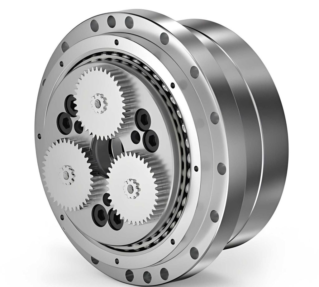
The fundamental architecture of a standard rotary vector reducer comprises two distinct, cascaded reduction stages. The first stage is a high-speed involute planetary gear train, and the second is a low-speed cycloidal-pin wheel planetary drive. The input rotation is delivered to the sun gear (or center gear), which meshes with two or three planet gears spaced at equal angles (e.g., 120° apart for a two-planet system, 180° for a two-planet system with specific phasing). This constitutes the first reduction stage. Each planet gear is integrated with a crank shaft via splines. These crank shafts are supported by bearings within the planet carrier (also called the output flange). The eccentric portions of the crank shafts support the cycloidal discs through roller bearings. Typically, two cycloidal discs are used, offset by 180° to balance forces. These discs mesh with a ring of stationary pins housed in the pin wheel (or housing). The planet carrier serves as the output member when the pin housing is fixed.
The kinematics of the rotary vector reducer are ingenious. Input rotation drives the sun gear, which in turn rotates the planet gears. This rotation is transmitted to the crank shafts. The crank shafts’ rotation causes the cycloidal discs to undergo an eccentric orbiting motion (revolution) around the central axis. Because the pin wheel is stationary, this orbiting motion forces the cycloidal discs to rotate on their own axes in the opposite direction to the crank shaft’s input rotation. This reverse rotation of the cycloidal discs is then transmitted back to the planet carrier via the crank shafts, causing the planet carrier to rotate at a greatly reduced speed. The total reduction ratio $i_{total}$ of the rotary vector reducer is given by:
$$ i_{total} = 1 + \frac{z_p}{z_s} \cdot z_{p2} $$
where $z_s$ is the sun gear tooth count, $z_{p2}$ is the planet gear tooth count in the first stage, and $z_p$ is the number of pins in the fixed ring. However, a more precise breakdown considers the two stages: the first-stage ratio $i_1 = 1 + \frac{z_{p2}}{z_s}$ (for a fixed carrier) and the second-stage cycloidal ratio $i_2 = \frac{z_p}{z_p – z_c}$, where $z_c$ is the number of lobes on the cycloidal disc (typically $z_c = z_p – 1$). For the standard configuration, the overall ratio simplifies to:
$$ i_{RV} = 1 + \frac{z_{p2}}{z_s} \cdot z_p $$
Design Requirements and Material Selection
The optimization of a rotary vector reducer must satisfy a comprehensive set of design and operational requirements to ensure reliable performance in demanding applications like industrial robotics.
| Design Requirement | Specification or Target |
|---|---|
| Transmission Efficiency ($\eta$) | > 85% |
| Positional Accuracy (Backlash) | Minimized, subject to strict tolerances |
| Service Life | Sufficient for high-cycle applications |
| Primary Optimization Goal | Minimum Volume / Mass |
| First-Stage Ratio ($i_1$) | Not too small to utilize cycloidal stage strength |
| Ratio Accuracy | Calculated $i_{RV}$ vs. target within ±5% |
| Geometric Relationship | Gear center distance $a_0 \approx (0.5-0.6)R_p$ ($R_p$: pin circle radius) |
Material selection and heat treatment are critical for achieving the necessary hardness, wear resistance, and fatigue strength to meet these requirements, especially for low backlash and high longevity. The following table summarizes typical choices for the key components of a high-performance rotary vector reducer.
| Component | Material | Heat Treatment | Hardness (HRC) |
|---|---|---|---|
| Sun Gear / Input Shaft | Alloy Steel (e.g., 20Cr, 20CrMnTi) | Carburizing and Quenching | 58-62 |
| Planet Gears | Alloy Steel (e.g., 20Cr, 20CrMnTi) | Carburizing and Quenching | 58-62 |
| Cycloidal Discs | Bearing Steel (e.g., GCr15) | Through-hardening (Quenching & Tempering) | 58-62 |
| Pins and Pin Wheel | Bearing Steel (e.g., GCr15) | Through-hardening (Quenching & Tempering) | 58-62 |
| Crank Shafts | Alloy Steel (e.g., 40Cr) | Quenching and Tempering | 45-50 |
Formulation of the Optimization Problem
The core of designing a compact rotary vector reducer lies in formulating and solving a constrained optimization problem. The objective is to minimize a metric directly related to the overall volume.
Objective Function and Design Variables
The overall volume of the rotary vector reducer is largely dictated by the dimensions of its two stages. A key geometric relationship, derived from design practice, states that the center distance $a_0$ of the first-stage planetary gears should be approximately 50% to 60% of the pin circle radius $R_p$ of the cycloidal stage. Minimizing $a_0$ therefore contributes significantly to minimizing the overall radius and volume of the reducer. Consequently, we select the center distance $a_0$ as the primary objective function to minimize.
$$ \text{Minimize: } f(\mathbf{X}) = a_0 = \frac{m}{2}(z_s + z_{p2}) $$
where $\mathbf{X} = [m, z_s, z_{p2}]^T$ is the vector of independent design variables: the gear module $m$, the sun gear tooth count $z_s$, and the planet gear tooth count $z_{p2}$. Other parameters become intermediate variables or are defined by constraints.
Constraint Conditions
The optimization must satisfy multiple engineering constraints to ensure a feasible and high-performing rotary vector reducer.
1. Bending Fatigue Strength (First Stage): The module must be sufficient to prevent tooth breakage under load.
$$ m \geq \sqrt[3]{\frac{2 K T_1 Y_{Fa} Y_{Sa}}{\psi_d z_s^2 [\sigma_F]}} $$
Here, $K$ is the load factor, $T_1$ is the torque on the sun gear, $Y_{Fa}$ and $Y_{Sa}$ are the tooth form factor and stress correction factor (obtainable via lookup tables or polynomial fits based on $z_s$), $\psi_d$ is the face width coefficient (often taken as 0.3-0.6 for planetary gears), and $[\sigma_F]$ is the allowable bending stress.
2. Contact Fatigue Strength (First Stage): The gear teeth must withstand surface pitting.
$$ m z_s \geq 2.32 \sqrt[3]{\frac{K T_1 (i_1+1)}{\psi_d i_1} \left( \frac{Z_E}{[\sigma_H]} \right)^2} $$
where $i_1 = z_{p2}/z_s$ is the first-stage ratio, $Z_E$ is the elasticity coefficient (189.9 $\sqrt{\text{MPa}}$ for steel-steel), and $[\sigma_H]$ is the allowable contact stress.
3. Transmission Ratio Accuracy: The designed ratio must match the specified ratio $i_{spec}$.
$$ \left| \frac{i_{RV} – i_{spec}}{i_{spec}} \right| \leq 0.05 \quad \text{where} \quad i_{RV} = 1 + \frac{z_{p2}}{z_s} z_p $$
$z_p$ is the number of pins, which is related to the cycloidal disc design.
4. Gear Tooth and Assembly Conditions:
- To avoid undercutting and ensure good mesh quality: $z_s \geq z_{min}$ (e.g., 17 for a standard 20° pressure angle).
- For balanced force transmission in the two-stage rotary vector reducer, the number of crank shafts (typically 2) often requires $z_s$ to be an even number or a multiple of the crank count for symmetric assembly.
- To ensure the first stage provides meaningful speed reduction before the high-torque cycloidal stage: $i_1 = z_{p2}/z_s \geq 1.5$.
5. Geometric Compatibility Between Stages: The center distance must fall within the empirical range relative to the pin circle radius.
$$ 0.5 R_p \leq a_0 \leq 0.6 R_p $$
The pin circle radius $R_p$ is preliminarily estimated based on output torque $T_{out}$:
$$ R_p \approx (0.85 \sim 1.3) \sqrt[3]{T_{out}} $$
where $T_{out} = 9550 \frac{P \cdot \eta_{total}}{n_{out}}$, $P$ is power, $n_{out}$ is output speed, and $\eta_{total}$ is total efficiency.
6. Efficiency Constraint: The overall efficiency $\eta_{total}$ must exceed the threshold (e.g., 85%). The efficiency can be estimated as:
$$ \eta_{total} = \eta_{gear} \cdot \eta_{cycloidal} \cdot \eta_{bearings}^N $$
A more detailed analysis for the planetary and cycloidal stages is complex but can be incorporated via empirical formulas or look-up functions based on gear parameters and ratios.
Optimization Design Example and Computational Procedure
To demonstrate the methodology, we consider the design of an RV-450E type rotary vector reducer with the following specifications:
- Rated Input Power ($P$): 4.28 kW
- Target Reduction Ratio ($i_{spec}$): 81
- Rated Output Speed ($n_{out}$): 5 rpm
The optimization problem is a single-objective, non-linear constrained problem. Computational tools like MATLAB are well-suited for this task. The `fmincon` solver can be employed. However, practical implementation must handle discrete variables (e.g., module $m$ from standard series, integer tooth counts $z_s$, $z_{p2}$, $z_p$). A pragmatic approach involves a segmented or iterative procedure:
- Parameter Initialization and Discrete Handling: Solve the continuous problem, then round/select the nearest standard values for discrete variables. Alternatively, use loops to iterate over a predefined set of standard modules.
- Sub-problem for First Stage: For a trial module $m$, find integer $z_s$ and $z_{p2}$ that satisfy strength constraints (Eq. 1 & 2), ratio constraints (linked to $z_p$), and geometric constraints (linked to $R_p$).
- Sub-problem for Second Stage: Determine $z_p$ (with $z_c = z_p – 1$) to meet the overall ratio $i_{RV}$ accurately. Calculate $R_p$ and verify $0.5R_p \leq a_0 \leq 0.6R_p$.
- Iteration and Evaluation: Iterate over possible combinations, evaluating the objective function $a_0$, and select the combination that yields the minimum $a_0$ while satisfying all constraints.
Applying this logic to the RV-450E example yields the following optimized parameters. For comparison, results from a reference conventional design are also presented.
| Design Parameter | Symbol | Optimized Design Value | Reference Design Value |
|---|---|---|---|
| Sun Gear Teeth | $z_s$ | 18 | 18 |
| Planet Gear Teeth | $z_{p2}$ | 35 | 38 |
| Gear Module (mm) | $m$ | 3 | 3 |
| Center Distance (mm) | $a_0$ | 79.5 | 84.0 |
| Number of Pins | $z_p$ | 42 | 38 |
| Cycloidal Disc Lobes | $z_c$ | 41 | 37 |
| Pin Circle Radius (mm) | $R_p$ | 154 | 155 |
| Eccentricity (mm) | $a$ | 3.0 | 3.0 |
| Achieved Ratio | $i_{RV}$ | 82.67 | 81.22 |
The results show excellent agreement with the reference design, validating the model’s correctness. Crucially, the optimized design achieves a smaller center distance $a_0$ (79.5 mm vs. 84.0 mm), which directly leads to a more compact first-stage gear train. Given the fixed relationship $a_0 \approx 0.55R_p$, this also implies a potentially smaller pin circle radius and, consequently, a more volume-efficient rotary vector reducer overall. The achieved ratio is well within the allowable 5% error margin of the target ratio of 81.
Conclusion
This article has detailed a structured methodology for the optimal design of a rotary vector reducer targeting minimum volume. The complete optimization model was developed, including the selection of an appropriate objective function (first-stage center distance $a_0$) and a comprehensive set of constraint functions encompassing gear strength, ratio accuracy, geometric compatibility, and assembly conditions. The practical need to handle discrete and integer variables was addressed through a segmented computational procedure suitable for implementation in engineering software like MATLAB. The design example for an RV-450E type reducer demonstrates the effectiveness of the approach, yielding parameters that align with known designs while achieving a measurably smaller and thus more optimal geometry. This systematic framework provides a solid foundation for the design and development of compact, high-performance rotary vector reducers essential for advanced robotic systems.