
As a pivotal component in industrial robotic joints, the Rotary Vector (RV) reducer is renowned for its high torque density, compact structure, and excellent precision. The core of its superior performance lies in the unique two-stage transmission mechanism. The second stage, comprising the cycloidal disc and the pinwheel housing, is particularly critical as it primarily determines the reducer’s ultimate load-carrying capacity and torsional rigidity. The standard cycloidal profile theoretically allows for near-half of the pins to engage simultaneously, distributing the load effectively. However, in practical manufacturing, specific profile modifications are essential to compensate for errors and ensure proper lubrication, which inevitably reduces the number of simultaneously engaged teeth and consequently the load capacity. Therefore, optimizing the fundamental parameters of the cycloidal pinwheel pair presents a significant avenue for enhancing the overall performance of the RV reducer.
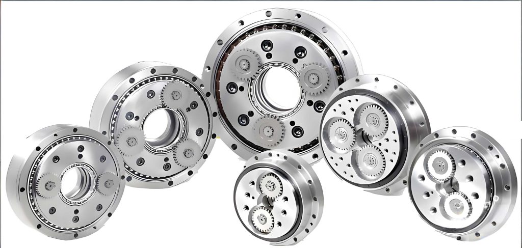
The传动原理 of an RV reducer can be summarized as follows: Input rotation is first transmitted to a central sun gear, which drives two or three planetary gears in the first-stage involute planetary gear train. These planetary gears are connected to crankshafts. The rotation of the crankshafts, which act as eccentric cams, drives the cycloidal discs. The cycloidal discs mesh with a stationary ring of pins (the pinwheel). Due to the difference in the number of teeth between the cycloidal disc (Z_c) and the pinwheel (Z_p), for each full revolution of the crankshaft, the cycloidal disc undergoes a small reverse rotation of (Z_p – Z_c)/Z_c turns. This motion is then output through a planet carrier mechanism. The force transmission within the cycloidal pair is the key to its high load capacity.
The contact force between the cycloidal disc and a pin is not uniform. The force is maximal at the pin with the longest lever arm relative to the output center. Assuming other contact forces are proportional to their respective lever arms, the torque transmitted by a single cycloidal disc, $T_e$, can be related to the maximum contact force, $F_{max}$. Considering manufacturing tolerances, the total output torque $T$ of the RV reducer is typically taken as $T = T_e / 0.55$ for a two-disc design. The relationship is given by:
$$ T = \frac{2.2 F_{max}}{k_1 Z_p r_p} $$
where $k_1$ is the shortening coefficient, $Z_p$ is the number of pins, and $r_p$ is the radius of the pin distribution circle. This equation highlights that the承载能力 is directly related to $F_{max}$. However, $F_{max}$ itself is a complex function of the cycloidal pair’s geometric parameters and load distribution, making direct analytical optimization challenging.
Mathematical Modeling for Parameter Optimization
The goal is to maximize the load-carrying capacity (output torque $T$) of the RV reducer under standardized external dimensions. Among the fundamental design parameters of the cycloidal pair, the eccentricity $a$ and the pin radius $r_{rp}$ are identified as the most influential variables that can be optimized without altering the overall reducer envelope. Therefore, the design variable vector $\mathbf{X}$ is defined as:
$$ \mathbf{X} = [a, r_{rp}]^T $$
The objective function is straightforward: maximize the output torque $T$.
$$ \text{max } f(\mathbf{X}) = T(\mathbf{X}) $$
This optimization is subject to several critical constraints derived from design principles and material limits:
- Geometric Feasibility: The shortening coefficient $k_1 = a Z_p / r_p$ and the pin radius coefficient $k_2 = r_{rp} / (r_p \sin(\pi / Z_p))$ must remain within practical ranges to ensure a proper tooth profile and pin strength.
- Tooth Profile Integrity: The pin radius must be smaller than the minimum absolute curvature radius of the unmodified cycloidal profile $|\rho_0|_{min}$ to avoid undercutting or pointed teeth.
$$ r_{rp} < |\rho_0|_{min} $$ - Contact Stress Limit: The maximum Hertzian contact stress $\sigma_{H, max}$ between the cycloidal disc and any pin must not exceed the allowable stress $[\sigma_H]$ of the material.
$$ \sigma_{H, max} = 0.418 \sqrt{\frac{F_{max} E_e}{b_c \rho_{ei}}} \leq [\sigma_H] $$
where $E_e$ is the equivalent elastic modulus, $b_c$ is the width of the cycloidal disc, and $\rho_{ei}$ is the equivalent curvature radius at the contact point. - Bearing Life Requirement: The calculated life $L$ of the crankshaft bearings (needle roller bearings) must meet or exceed the required service life $L_p$.
$$ L = \frac{10^6}{60 n} \left( \frac{C}{P} \right)^\epsilon \geq L_p $$
Here, $n$ is the relative speed, $C$ is the dynamic load rating, $P$ is the equivalent dynamic load, and $\epsilon$ is the life exponent.
The relationship between the design variables ($a$, $r_{rp}$) and the objective $T$ is implicit, governed by the complex contact mechanics encapsulated in constraints (3) and (4). A direct analytical solution is intractable, necessitating a numerical optimization approach.
Genetic Algorithm with an Enhanced Fitness Evaluation
A Genetic Algorithm (GA) is employed for its effectiveness in navigating non-linear, constrained search spaces. The core challenge lies in efficiently evaluating the fitness (i.e., calculating $T$) for a given set of parameters $\mathbf{X}=[a, r_{rp}]$. An enhanced fitness function procedure is developed to address this:
The algorithm starts with a candidate solution $\mathbf{X}$ that satisfies the simple geometric constraints (1 & 2). For this candidate, an initial guess for the output torque $T_0$ is assumed. Using this $T_0$, the corresponding maximum contact force $F_{max}$ and bearing load are calculated via the force distribution model. Subsequently, the maximum contact stress ratio $R_1 = \sigma_{H, max} / [\sigma_H]$ and the bearing life ratio $R_2 = L / L_p$ are computed.
The evaluation logic is as follows:
– If both $R_1$ and $R_2$ are within a tight tolerance band (e.g., [0.995, 1.0]), the assumed torque $T_0$ is considered the valid load capacity for that $\mathbf{X}$.
– If $\max(R_1, R_2) < 0.995$, the design is under-stressed. The torque $T_0$ is iteratively increased until one of the ratios enters the target band.
– If $\min(R_1, R_2) > 1.0$, the design violates a constraint. The torque $T_0$ is iteratively decreased. A large step is used if the violation is severe (e.g., ratio > 1.5), else a smaller step is used.
– If adjustment leads to an under-stress condition, a bisection search between the last over-stress and under-stress torque values is conducted to find the optimal $T$.
This procedure effectively turns the optimization problem into finding the parameters $\mathbf{X}$ that yield the highest torque $T$ for which both critical constraints are active (i.e., at their limits). The following table summarizes the GA parameters used for this optimization.
| GA Parameter | Value |
|---|---|
| Population Size | 50 |
| Maximum Generations | 500 |
| Crossover Probability | 0.4 |
| Mutation Probability | 0.1 |
| Selection Method | Roulette Wheel |
Case Study: Optimization of an RV-20E Reducer
The proposed methodology is applied to optimize a commercial RV-20E RV reducer. The fixed baseline parameters are listed below.
| Parameter | Symbol | Value |
|---|---|---|
| Number of Cycloidal Teeth | $Z_c$ | 39 |
| Number of Pins | $Z_p$ | 40 |
| Pin Distribution Circle Radius | $r_p$ | 51.5 mm |
| Cycloidal Disc Width | $b_c$ | 10.2 mm |
| Original Eccentricity | $a_0$ | 1.0 mm |
| Original Pin Radius | $r_{rp0}$ | 2.5 mm |
For the variables $a$ and $r_{rp}$, the feasible ranges are determined as $a \in [0.85, 1.15]$ mm and $r_{rp} \in [2.50, 4.05]$ mm based on the geometric constraints. The GA was executed in MATLAB, and the convergence of the best fitness value (load capacity) over generations is shown conceptually. The algorithm converged to an optimal solution.
The optimization results are summarized in the following table, comparing them with the original design.
| Parameter / Performance | Original Design | Optimized Design | Change |
|---|---|---|---|
| Eccentricity, $a$ (mm) | 1.00 | 0.96 | -4.0% |
| Pin Radius, $r_{rp}$ (mm) | 2.50 | 2.52 | +0.8% |
| Shortening Coefficient, $k_1$ | 0.7767 | 0.7456 | -4.0% |
| Calculated Load Capacity, $T$ (N·m) | 263.92 | 293.34 | +11.15% |
The numerical analysis indicates that the optimized fundamental parameters for the cycloidal pinwheel pair yield a significant 11.15% increase in the theoretical load-carrying capacity of the RV reducer. The slight decrease in eccentricity and minimal increase in pin radius modify the contact geometry and stress distribution favorably, allowing the mechanism to operate closer to the material and bearing limits, thus harnessing more of its inherent potential.
Experimental Validation and Performance Comparison
To validate the theoretical optimization, new cycloidal discs and pins were manufactured according to the optimized parameters ($a=0.96$ mm, $r_{rp}=2.52$ mm). The tooth profile itself employed the same segmented modification strategy as the original design to ensure comparability. These components were assembled into a complete RV-20E RV reducer. Both the original and the optimized reducers were tested on a precision reducer comprehensive performance test bench according to relevant standards.
The tests measured transmission efficiency, temperature rise, and noise under light load (50 N·m), rated load (167 N·m), and heavy load (400 N·m) conditions at an output speed of 15 rpm. The results, averaged over multiple runs, are presented below.
| Load Condition | Metric | Original RV Reducer | Optimized RV Reducer | Improvement |
|---|---|---|---|---|
| Rated Load (167 N·m) | Efficiency (%) | 80.5 | 82.8 | +2.3% |
| Temperature Rise (°C) | ΔT_orig | ΔT_orig – 0.7 | -0.7 °C | |
| Noise (dB) | N_orig | N_orig – 1 | -1 dB | |
| Heavy Load (400 N·m) | Efficiency (%) | 81.2 | 84.4 | +3.2% |
| Temperature Rise (°C) | ΔT_heavy_orig | ΔT_heavy_orig – 1.0 | -1.0 °C | |
| Noise (dB) | N_heavy_orig | N_heavy_orig – 2 | -2 dB |
The experimental data strongly corroborates the optimization outcome. The optimized RV reducer demonstrates superior performance under load:
1. Higher Efficiency: The increase in efficiency (2.3% at rated load, 3.2% at heavy load) directly indicates lower power loss, which is consistent with a more favorable force transmission and reduced parasitic losses.
2. Lower Temperature Rise: Reduced power loss translates to less heat generation, explaining the lower temperature rise of the optimized unit.
3. Reduced Noise: The notable reduction in noise, especially under heavy load, suggests smoother meshing engagement and lower vibration levels, which are indirect indicators of improved load distribution and reduced stress concentrations.
The performance gains under heavy load are more pronounced, confirming that the optimization successfully enhanced the fundamental load-carrying capacity of the cycloidal drive. The improved parameters allow the RV reducer
Conclusion
This work presents a systematic approach for optimizing the fundamental parameters of the cycloidal pinwheel pair to enhance the load capacity of an RV reducer. By identifying the eccentricity $a$ and pin radius $r_{rp}$ as key variables and formulating a constrained optimization problem with the maximum output torque as the objective, a significant performance improvement was achieved. The use of a Genetic Algorithm, augmented with an efficient fitness evaluation routine that directly links parameters to the limiting constraints (contact stress and bearing life), proved effective in navigating the complex design space.
The case study on an RV-20E reducer yielded an optimized parameter set ($a=0.96$ mm, $r_{rp}=2.52$ mm), which increased the theoretical load capacity by 11.15%. Experimental validation on physical prototypes confirmed the practical benefits, showing measurable improvements in transmission efficiency, thermal performance, and acoustic behavior under both rated and heavy load conditions. This methodology provides a valuable tool for the design and enhancement of high-performance RV reducers, contributing to the development of more capable and reliable robotic drive systems.