
I treat the programmable logic controller, or PLC, as the operational nervous system of an intelligent machining line built around the industrial robot. In my view, the industrial robot provides motion, dexterity, and repeatable manipulation, while the PLC provides timing, logic, coordination, data exchange, and safety enforcement. When I design, commission, or optimize such a line, I do not see the PLC as a simple relay replacement. I see it as the central automation layer that connects the industrial robot controller, computer numerical control machines, conveyors, automatic guided vehicles, sensors, vision systems, safety devices, and upper-level manufacturing execution systems. The result is a production cell that can run with higher availability, faster changeover, better traceability, and stronger safety than a collection of independent machines.
My first-person perspective is practical. I start with the process sequence, not with the hardware. I ask what the industrial robot must do, what the machining equipment must receive, what the logistics system must deliver, what the quality system must verify, and what the safety system must prevent. From those answers, I derive the PLC input and output list, the communication architecture, the program structure, the data model, and the safety logic. This approach keeps the industrial robot, PLC, and machining process aligned. It also makes the line easier to expand when product variants change or when new sensors and actuators are added.
The following discussion explains how I apply PLC technology in industrial robot intelligent machining lines. I focus on the central control role, flexible manufacturing, data foundations, safety barriers, multi-robot collaboration, logistics integration, adaptive parameter control, digital management, safety control implementation, communication architecture, performance metrics, implementation roadmap, risks, and future directions. I use tables and mathematical expressions to summarize the relationships that matter most in my engineering work.
1. My View of the PLC as the Central Control Hub
In my projects, the PLC is the central control hub because it receives signals from the physical world, executes deterministic logic, and issues commands that move the industrial robot and machining equipment through a defined sequence. The industrial robot controller may calculate joint trajectories, but the PLC decides when the robot is allowed to enter a station, when the machine door may open, when the fixture may clamp, when the conveyor may advance, and when the finished part may leave. This division of responsibility is essential. The industrial robot handles local motion intelligence, while the PLC handles cell-level orchestration.
I structure the PLC program around states, transitions, interlocks, and permissions. A state represents a stable condition, such as waiting for material, robot loading, machining, robot unloading, inspection, or sorting. A transition is allowed only when the required conditions are true. An interlock prevents unsafe or illogical actions, such as opening a machine door while the spindle is rotating. A permission grants an industrial robot or machine controller the right to perform a specific action. This structure is easy to diagnose and easy to extend.
The scan cycle is the fundamental timing unit of the PLC. I express it as follows:
$$T_{scan}=T_{input}+T_{logic}+T_{output}+T_{comm}$$
Here, $$T_{input}$$ is the time required to read input modules, $$T_{logic}$$ is the time required to execute the control program, $$T_{output}$$ is the time required to update output modules, and $$T_{comm}$$ is the time required for network communication with the industrial robot and other devices. If the scan cycle becomes too long, the line may respond slowly to safety events or miss short sensor pulses. Therefore, I keep high-speed safety functions in a dedicated safety PLC or in a safety-rated network segment whenever the risk assessment requires it.
For a machining cell with multiple stations, the cycle time is not simply the sum of all actions. It is usually determined by the longest station path plus synchronization overhead. I use the following expression:
$$T_{cycle}=\max_{i=1}^{n}\left(\sum_{j=1}^{m_i} t_{i,j}\right)+T_{sync}$$
In this equation, $$t_{i,j}$$ is the time of operation $$j$$ at station $$i$$, and $$T_{sync}$$ is the additional time needed for handshakes, robot transfers, and safety checks. Throughput is then:
$$Q=\frac{1}{T_{cycle}}$$
I use these equations to decide where to add parallel stations, where to overlap robot motion with machining, and where to reduce communication delays. The industrial robot is often the most flexible element in the line, but it can also become the bottleneck if the PLC does not overlap its tasks intelligently.
| PLC Responsibility | What I Implement | Why It Matters for the Industrial Robot Line |
|---|---|---|
| Signal acquisition | Read proximity sensors, limit switches, pressure switches, safety devices, and machine status contacts | Provides real-time awareness of fixtures, doors, pallets, and industrial robot readiness |
| Logic execution | Evaluate interlocks, permissives, sequences, timers, counters, and alarms | Prevents conflicting actions between the industrial robot and machining equipment |
| Command output | Control valves, contactors, indicators, grippers, conveyors, and robot start signals | Converts decisions into physical actions with deterministic timing |
| Communication | Exchange data with industrial robot controllers, CNC systems, vision systems, and supervisory systems | Enables coordinated production and traceability |
| Diagnostics | Monitor faults, cycle times, device health, and communication status | Reduces mean time to repair and improves line availability |
| Safety enforcement | Execute safe stop, emergency stop, guard monitoring, and safe state transitions | Protects operators and equipment around the industrial robot |
I also define the control hierarchy clearly. The industrial robot controller owns joint-level motion, servo tuning, and local trajectory execution. The PLC owns cell-level sequencing, material flow, mode management, and safety interlocking. The supervisory system owns production orders, reporting, and long-term data storage. When this hierarchy is respected, the industrial robot and PLC cooperate instead of competing for control.
2. How I Use PLC for Flexible Manufacturing
Flexible manufacturing is one of the strongest reasons I rely on PLC technology. An industrial robot intelligent machining line must often produce multiple part numbers, handle small batch sizes, and switch between variants without a long mechanical changeover. The industrial robot can be reprogrammed, but the entire line must also be reprogrammed at the cell level. The PLC makes this possible through modular programming, parameter sets, recipe management, and communication with the industrial robot controller.
I divide the PLC program into reusable function blocks. Each function block represents a machine action, a station sequence, a safety zone, or a product-specific operation. When a new product is introduced, I do not rewrite the entire program. I create or modify the recipe data, select the appropriate function blocks, and adjust the parameters that the industrial robot and machining equipment use. This modularity reduces engineering time and reduces the risk of introducing errors into already validated logic.
I measure flexibility by how quickly the line can change from one product to another while maintaining quality and safety. A simple flexibility index can be written as:
$$F=\frac{N_{variants}}{T_{changeover}}$$
Here, $$N_{variants}$$ is the number of product variants that the line can produce within a defined period, and $$T_{changeover}$$ is the average time required to switch from one variant to another. I improve $$F$$ by increasing the number of stored recipes, reducing mechanical adjustments, and using the industrial robot with multiple end effectors or quick-change grippers.
I also use a weighted flexibility capability model:
$$C_{flex}=\alpha M+\beta R+\gamma S+\delta P$$
In this expression, $$M$$ represents modularity, $$R$$ represents reconfigurability, $$S$$ represents scalability, and $$P$$ represents programmability. The coefficients $$\alpha$$, $$\beta$$, $$\gamma$$, and $$\delta$$ reflect the relative importance of each factor in a specific production environment. When I apply this model, I usually find that programmability and modularity have the greatest influence on how quickly an industrial robot cell can adapt.
| Flexibility Mechanism | PLC Implementation | Industrial Robot Benefit |
|---|---|---|
| Recipe management | Store part-specific parameters in data blocks and recall them by part number | The industrial robot receives the correct pick, place, and path parameters for each variant |
| Modular function blocks | Create standard blocks for load, unload, clamp, inspect, and sort | Reduces reprogramming effort when the industrial robot task changes |
| Mode management | Define manual, automatic, maintenance, and setup modes with different permissions | Allows safe industrial robot jogging and teaching without disrupting production logic |
| Parameter switching | Change speeds, offsets, tool numbers, and machining parameters through recipes | Enables the industrial robot to handle different part geometries |
| Communication mapping | Use structured data exchange with the industrial robot controller | Keeps the robot program and PLC sequence synchronized |
| Scalable I/O | Add remote I/O modules and network segments as stations expand | Supports additional industrial robot stations without replacing the main controller |
When I switch production from one part family to another, I follow a controlled sequence. First, I verify that the required fixture and gripper are installed. Second, I load the recipe into the PLC. Third, the PLC sends the corresponding program number and parameter set to the industrial robot controller. Fourth, the PLC verifies that the CNC program and tool offsets are correct. Fifth, I run a dry cycle without material. Sixth, I run a first-article inspection. Only after these steps do I release the line for automatic production. This discipline prevents the industrial robot from moving to an incorrect position or machining the wrong feature.
3. PLC as the Data Foundation for Intelligent Decisions
I see the PLC as the first data layer in an industrial robot intelligent machining line. Before data can be analyzed by a manufacturing execution system, a data historian, or an artificial intelligence model, it must be collected reliably, filtered, time-stamped, and contextualized. The PLC performs this role at the edge. It reads machine signals, converts analog values, validates ranges, and transmits structured data to higher-level systems.
The data rate from the PLC to the supervisory layer depends on the number of sensors, the sampling frequency, and the number of bytes per sample. I use the following relationship:
$$R_{data}=N_{sensors} \cdot f_s \cdot B_{sample}$$
In this equation, $$N_{sensors}$$ is the number of data sources, $$f_s$$ is the sampling frequency, and $$B_{sample}$$ is the number of bytes per sample. If $$R_{data}$$ exceeds the available network bandwidth, I reduce the sampling rate for non-critical signals, use edge buffering, or apply event-based reporting. Critical safety and interlock signals remain local and deterministic.
Data quality is equally important. I define a simple data quality ratio as:
$$D_{quality}=1-\frac{N_{invalid}}{N_{total}}$$
Here, $$N_{invalid}$$ is the number of invalid, missing, or out-of-range records, and $$N_{total}$$ is the total number of records. I aim for a high $$D_{quality}$$ by using shielded wiring, proper grounding, scalable communication, and PLC logic that rejects impossible values. For example, if a temperature sensor reports a value outside its physical range, the PLC flags the signal as invalid rather than passing it to the quality database.
| Data Category | Example Signals | PLC Preprocessing | Use in Intelligent Decisions |
|---|---|---|---|
| Industrial robot status | Mode, program number, servo ready, cycle time, fault code | Debounce, status mapping, time stamping | Robot utilization, fault prediction, cycle optimization |
| Machining parameters | Spindle speed, feed rate, cutting force, temperature | Scaling, filtering, limit checking | Adaptive control, tool wear estimation |
| Quality data | Dimensions, vision results, pass/fail flags | Format conversion, result aggregation | First-pass yield, root cause analysis |
| Logistics data | AGV position, conveyor speed, stock level | Event detection, queue tracking | Material flow optimization |
| Energy data | Power, air pressure, coolant flow | Pulse counting, averaging | Energy efficiency, maintenance triggers |
| Safety data | Guard status, emergency stop, light curtain | Safety-rated logic, redundant validation | Incident analysis, compliance reporting |
I also use the PLC to contextualize data. A spindle speed value alone is not very useful. A spindle speed value associated with a specific part number, tool number, industrial robot program, and time stamp is far more useful. This context allows me to compare cycles, detect drift, and build predictive models that respect the actual production conditions.
4. PLC as My Safety Barrier
Safety is not an add-on in my design process. It is a primary function of the control architecture. The industrial robot can move quickly and carry significant kinetic energy. The machining equipment can rotate, cut, clamp, and eject material. Therefore, I use a safety PLC or a safety-rated PLC segment to monitor guards, emergency stops, light curtains, door switches, enabling devices, and safe speed limits.
The stopping performance of the system is a critical design parameter. I express the stopping time as:
$$t_{stop}=t_{detect}+t_{PLC}+t_{brake}$$
Here, $$t_{detect}$$ is the time required for the sensor to detect the event, $$t_{PLC}$$ is the time required for the safety logic to react, and $$t_{brake}$$ is the time required for the industrial robot or machine to reach a safe state. The safety distance is then:
$$d_{safe}=v_{max}\left(t_{detect}+t_{PLC}+t_{brake}\right)+d_{margin}$$
In this equation, $$v_{max}$$ is the maximum approach speed, and $$d_{margin}$$ is an additional allowance for measurement uncertainty and wear. I calculate this distance for every access point around the industrial robot cell. If the calculated distance is greater than the available space, I use physical guards, light curtains with muting, or safe speed reduction.
| Safety Device | PLC Function | Expected Action |
|---|---|---|
| Emergency stop button | Monitor normally closed contacts and safety input channels | Remove power from hazardous actuators and stop the industrial robot |
| Safety light curtain | Detect entry into the robot work envelope | Trigger a protective stop or safe speed limit |
| Guard door switch | Verify that the guard is closed before automatic operation | Prevent automatic start when the guard is open |
| Enabling device | Allow motion only while the operator holds the device | Enable limited manual motion for teaching or maintenance |
| Safe torque off | Remove drive torque without removing all power | Stop the industrial robot and spindle safely |
| Muting sensors | Distinguish material from personnel | Allow material to pass without unnecessary stops |
| Safety relay | Provide redundant switching for safety outputs | Ensure a safe state even if one channel fails |
I also use the PLC to enforce zone control. The industrial robot work envelope is divided into zones. A zone may be open to operators, restricted, or locked. The PLC checks the zone state before granting motion permission. If a person enters a restricted zone, the PLC reduces speed or stops the industrial robot. If a maintenance mode is active, the PLC changes the safety logic to allow limited motion while preventing automatic production.
5. Collaborative Control of Multiple Industrial Robots
In many intelligent machining lines, one industrial robot is not enough. I often work with cells that include several industrial robots performing loading, unloading, welding, inspection, deburring, and assembly. The PLC coordinates these industrial robots by exchanging status and command signals, managing shared resources, and preventing collisions. The industrial robot controllers handle local path planning, but the PLC handles cell-level task allocation and synchronization.
I formulate multi-robot task allocation as a binary optimization problem. Let $$x_{ij}=1$$ if task $$i$$ is assigned to industrial robot $$j$$, and $$x_{ij}=0$$ otherwise. The objective is:
$$\min \sum_{i=1}^{n}\sum_{j=1}^{m} c_{ij}x_{ij}$$
Subject to:
$$\sum_{j=1}^{m}x_{ij}=1,\quad \forall i$$
$$\sum_{i=1}^{n}x_{ij}\leq 1,\quad \forall j$$
$$x_{ij}\in\{0,1\}$$
Here, $$c_{ij}$$ is the cost of assigning task $$i$$ to industrial robot $$j$$. The cost may include travel time, cycle time, energy consumption, or risk. The first constraint ensures that every task is assigned exactly once. The second constraint prevents an industrial robot from being assigned more than one task at the same time. I solve this problem in the PLC at a coarse level, or I send the assignment to a supervisory optimizer and receive the result through communication.
For path planning, I use a weighted cost function:
$$J=w_1 L+w_2 T+w_3 E+w_4 C$$
In this equation, $$L$$ is path length, $$T$$ is travel time, $$E$$ is energy consumption, and $$C$$ is collision risk. The weights $$w_1$$, $$w_2$$, $$w_3$$, and $$w_4$$ depend on the production objective. If throughput is the priority, I increase $$w_2$$. If energy cost is high, I increase $$w_3$$. If the industrial robot moves near operators or other robots, I increase $$w_4$$.
For synchronized motion, I define the start time of industrial robot $$i$$ as:
$$t_{start,i}=t_{ref}+\phi_i$$
where the offset is:
$$\phi_i = \frac{\Delta d_i}{v_{max}}+\Delta t_{process}$$
Here, $$\Delta d_i$$ is the distance offset from the reference point, and $$\Delta t_{process}$$ is the process time difference. This equation allows me to stagger robot motions so that two industrial robots do not enter the same space at the same time.
Collision avoidance is enforced through a safe distance:
$$d_{safe}=v_{max}\tau_{react}+d_{margin}$$
In this expression, $$\tau_{react}$$ is the total reaction time of the sensor, PLC, network, and robot controller. I use this value to define exclusion zones and speed limits. If the distance between two industrial robots falls below $$d_{safe}$$, the PLC reduces speed or pauses one robot until the zone is clear.
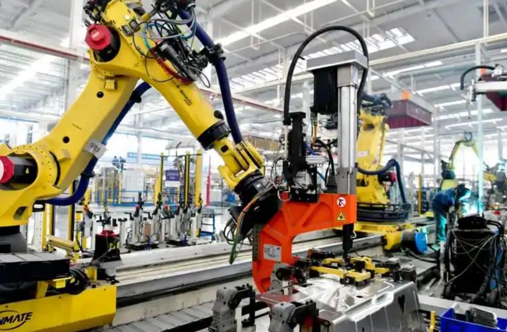
This visual reference reminds me that the industrial robot is only one part of a larger system. The PLC, sensors, network, safety devices, and machining equipment must all work together. When I look at an industrial robot cell, I see data flows, power flows, material flows, and safety flows. The PLC is the component that coordinates those flows in real time.
| Collaboration Mode | PLC Role | Industrial Robot Role | Typical Application |
|---|---|---|---|
| Handover | Permit transfer when both robots are in position | One robot holds the part while the other takes it | Assembly, machine tending |
| Parallel processing | Divide tasks and monitor cycle balance | Each robot performs a separate operation | Welding, deburring, inspection |
| Shared fixture | Lock and unlock fixture access | Robots load and unload from the same fixture | CNC machining cells |
| Following motion | Synchronize start and speed commands | Robots move along coordinated paths | Large part handling |
| Dynamic reassignment | Reallocate tasks based on availability | Robots switch between tasks | Flexible manufacturing |
| Safety zone sharing | Manage zone permissions and safe stops | Robots slow down or stop when zones overlap | Human-robot collaboration |
6. Intelligent Logistics Integration
I integrate the industrial robot cell with intelligent logistics so that material arrives at the right place at the right time. The PLC controls conveyors, automatic guided vehicles, rail-guided vehicles, stacker cranes, transfer units, and robotic grippers. The industrial robot performs pick-and-place tasks, but the PLC decides when the material is available, where it must go, and what priority it has.
For AGV dispatching, I use a cost-minimization model. Let $$c_{ij}$$ be the cost of sending vehicle $$i$$ to task $$j$$. The assignment problem is:
$$\min \sum_{i=1}^{n}\sum_{j=1}^{m} c_{ij}x_{ij}$$
Subject to:
$$\sum_{j=1}^{m}x_{ij}\leq 1,\quad \forall i$$
$$\sum_{i=1}^{n}x_{ij}=1,\quad \forall j$$
$$x_{ij}\in\{0,1\}$$
The PLC executes the dispatching logic and communicates with the AGV fleet manager. If the fleet manager is unavailable, the PLC can fall back to a simple priority rule. For example, it can send the nearest idle AGV to the highest-priority station. This fallback keeps the line running during network interruptions.
I also monitor queue length and buffer occupancy. A simple queue model is:
$$L_q=\lambda W_q$$
Here, $$L_q$$ is the average number of items in the queue, $$\lambda$$ is the arrival rate, and $$W_q$$ is the average waiting time. If $$L_q$$ becomes too large, the PLC slows upstream production or requests additional logistics capacity. If $$W_q$$ becomes too long, the PLC prioritizes the affected station to prevent starvation.
| Logistics Device | PLC Control Function | Industrial Robot Interaction |
|---|---|---|
| Conveyor | Start, stop, speed control, zone tracking | Industrial robot picks from or places onto conveyor |
| AGV | Dispatch, route permission, handshake | Industrial robot loads or unloads AGV |
| Transfer unit | Position control, clamp, release | Industrial robot receives part from transfer unit |
| Stacker crane | Storage and retrieval commands | Industrial robot interfaces with pallet or bin |
| Buffer station | Occupancy detection, priority management | Industrial robot uses buffer to decouple stations |
| Gripper | Open, close, pressure verification | Industrial robot uses gripper to handle material |
| Vision station | Trigger inspection, receive result | Industrial robot presents part to camera |
I design the logistics handshake carefully. The industrial robot must not attempt to pick a part unless the PLC confirms that the part is present, the fixture is released, and the safety zone is clear. The conveyor must not advance unless the industrial robot has cleared the transfer zone. The AGV must not leave unless the PLC confirms that the load is secure. These handshakes are simple, but they prevent most material handling faults.
7. Adaptive Machining Parameter Control
I use the PLC for adaptive machining parameter control because fixed parameters cannot always handle material variation, tool wear, and thermal drift. The industrial robot may present the part accurately, but the machining process itself must adapt to the actual conditions. The PLC reads force, temperature, vibration, power, and vision data, compares the data with reference values, and adjusts speed, feed, depth, or robot positioning parameters.
I often implement a PID control law for adaptive adjustment:
$$u(t)=K_p e(t)+K_i \int_0^t e(\tau)d\tau+K_d \frac{de(t)}{dt}$$
Here, $$e(t)$$ is the error between the reference and measured value. For cutting force control, the error is:
$$e(t)=F_{ref}-F_{meas}$$
The output $$u(t)$$ may adjust feed rate, spindle speed, or robot feed. I tune $$K_p$$, $$K_i$$, and $$K_d$$ carefully because aggressive tuning can cause oscillation and poor surface finish.
I also use a simplified cutting force model:
$$F_c=K_c a_p f_z \sin\kappa$$
In this equation, $$F_c$$ is the cutting force, $$K_c$$ is the specific cutting force coefficient, $$a_p$$ is the depth of cut, $$f_z$$ is the feed per tooth, and $$\kappa$$ is the cutting edge angle. When the measured force increases, the PLC may reduce $$a_p$$ or $$f_z$$ to protect the tool and the workpiece.
Tool wear can be estimated with a linear or nonlinear model:
$$VB=a+bt+cF_c$$
Here, $$VB$$ is the flank wear, $$t$$ is cutting time, and $$F_c$$ is the cutting force. When $$VB$$ exceeds a threshold, the PLC sends a tool change request or compensates by adjusting the industrial robot offset and machining parameters.
| Measured Variable | Sensor Type | PLC Action | Effect on Industrial Robot |
|---|---|---|---|
| Cutting force | Dynamometer or spindle current sensor | Reduce feed or speed, flag tool wear | Adjust robot feed or wait for tool change |
| Temperature | Thermocouple or infrared sensor | Adjust coolant, reduce speed, pause cycle | Delay robot unloading until safe temperature |
| Vibration | Accelerometer | Reduce speed, change feed, trigger alarm | Modify robot path to avoid chatter |
| Dimension error | Vision system or probe | Adjust offsets, reject part, request rework | Reposition industrial robot for correction |
| Surface quality | Vision or laser scanner | Classify part, adjust finishing parameters | Sort part to pass, rework, or reject lane |
| Power consumption | Power meter | Detect overload, optimize cycle | Reduce robot acceleration if power limit is reached |
I prefer to keep the adaptive control loop local to the PLC for fast response. The PLC can update the machining parameters within milliseconds, while the industrial robot receives corrected offsets or permission signals. For complex optimization, the PLC sends data to a supervisory system, receives a new parameter set, and applies it at the next safe transition.
8. Digital Production Line Management
I treat the PLC as the execution terminal of the digital production line management system. The management system may plan orders, schedule resources, and analyze performance, but the PLC executes the plan and reports what actually happened. This closed loop is essential for accurate management. Without PLC data, the digital system would rely on manual entry and delayed reports.
I use the overall equipment effectiveness metric to evaluate the line:
$$OEE=A \cdot P \cdot Q$$
Here, $$A$$ is availability, $$P$$ is performance, and $$Q$$ is quality. Availability can be expressed as:
$$A=\frac{MTBF}{MTBF+MTTR}$$
where $$MTBF$$ is mean time between failures and $$MTTR$$ is mean time to repair. The PLC contributes to $$A$$ by detecting faults early, guiding maintenance, and reducing troubleshooting time. It contributes to $$P$$ by optimizing cycle times and reducing micro-stops. It contributes to $$Q$$ by enforcing process parameters and recording inspection results.
| Management Function | PLC Data Source | Decision Supported |
|---|---|---|
| Production scheduling | Station status, cycle counts, queue levels | Release orders to the industrial robot cell |
| Quality traceability | Part ID, machining parameters, inspection results | Trace defects to process conditions |
| Maintenance planning | Running hours, fault codes, sensor trends | Schedule preventive maintenance |
| Energy management | Power, air, coolant, robot energy use | Identify inefficient cycles |
| Tool management | Cutting time, force, wear estimates | Replace tools before failure |
| Inventory control | Material consumption, buffer levels | Replenish raw material and consumables |
| Performance analysis | Cycle time, downtime reason, OEE inputs | Improve bottleneck stations |
I also build a product quality record for every part. The record includes the part identifier, industrial robot program number, machining program number, tool identifiers, measured parameters, inspection results, and time stamps. If a defect appears later, I can trace it back to the exact cycle. This traceability is valuable for continuous improvement and customer confidence.
9. Safety Control System Implementation
I implement safety control with a dedicated safety PLC or a safety-rated controller that meets the required safety integrity level. The safety PLC is separate from the standard PLC in critical applications, or it is integrated with redundant and diverse channels in compact applications. The safety PLC monitors emergency stops, guard doors, light curtains, enabling switches, safe position sensors, and safe speed sensors.
I use the following relationship to evaluate safety response:
$$t_{response}=t_{sensor}+t_{logic}+t_{actuator}$$
The total response time must be less than the time required for a hazardous motion to reach the operator or a protected zone. This condition is:
$$t_{response} < \frac{d_{available}}{v_{max}}$$
Here, $$d_{available}$$ is the available distance between the hazard and the operator, and $$v_{max}$$ is the maximum hazard speed. If the condition cannot be satisfied, I increase the distance, reduce the speed, or use a faster safety device.
| Safety Function | Implementation | Verification Method |
|---|---|---|
| Emergency stop | Redundant safety input and safety output channels | Functional test and channel fault test |
| Guard monitoring | Dual-channel door switches with discrepancy checking | Open and close test during commissioning |
| Light curtain | Safety-rated input with muting logic | Test with calibrated test rod |
| Safe speed | Safety encoder and drive safety function | Speed measurement and stop time test |
| Safe direction | Safety-rated motion monitoring | Direction verification under load |
| Zone control | Safety PLC logic with zone permissions | Zone entry and exit test |
| Operator authentication | Login and permission management | Access level test and audit log review |
I also ensure that the safety system cannot be bypassed easily. Muting is allowed only under specific conditions and for a limited time. Maintenance mode requires a key switch or authenticated login. Manual mode reduces speed and limits motion. Every safety event is logged with a time stamp, device identifier, and operator identifier if applicable. This logging supports incident investigation and continuous safety improvement.
10. Integration Architecture and Communication
I design the communication architecture with determinism, openness, and diagnosability in mind. The industrial robot controller, PLC, CNC, vision system, AGV manager, and supervisory system must exchange data reliably. I use industrial Ethernet protocols such as PROFINET, EtherNet/IP, EtherCAT, and OPC UA. The choice depends on cycle time requirements, vendor compatibility, and the need for semantic data modeling.
Network latency is a key design parameter. I express total latency as:
$$T_{lat}=T_{proc}+T_{queue}+T_{tx}+T_{prop}$$
Here, $$T_{proc}$$ is processing time, $$T_{queue}$$ is queuing delay, $$T_{tx}$$ is transmission time, and $$T_{prop}$$ is propagation time. For safety and motion coordination, I keep $$T_{lat}$$ within the limits required by the application. For non-critical reporting, higher latency is acceptable.
Reliability is also important. I use the exponential reliability model:
$$R(t)=e^{-\lambda t}$$
Here, $$\lambda$$ is the failure rate. I reduce $$\lambda$$ by using industrial-grade components, redundant network paths for critical sections, and proper grounding and shielding. The PLC can also monitor communication health and switch to a safe fallback mode if a device stops responding.
| Protocol | Typical Use | PLC Role | Industrial Robot Integration |
|---|---|---|---|
| PROFINET | Real-time I/O and motion coordination | Master or controller | Exchange status, commands, and safety signals |
| EtherNet/IP | Discrete and process control | Scanner or adapter | Integrate robot controller into cell network |
| EtherCAT | High-speed motion and I/O | Master | Support fast robot and servo synchronization |
| OPC UA | Supervisory data exchange | Server or client | Provide contextualized robot and process data |
| MQTT | Lightweight telemetry | Publish data to broker | Send robot status to cloud or dashboard |
| Modbus TCP | Legacy device integration | Client or server | Connect older robot peripherals |
| Safety over Ethernet | Safety-rated communication | Safety controller | Transmit safe stop and zone signals |
I separate the network into zones. The safety network carries safety-rated signals. The control network carries real-time commands and status. The supervisory network carries production data. The enterprise network carries business data. Firewalls and gateways control traffic between zones. This architecture improves security and reduces the risk of a non-critical network issue affecting real-time control.
11. Performance Evaluation and My Design Metrics
I evaluate the industrial robot intelligent machining line with a balanced set of metrics. Throughput alone is not enough. I also consider quality, availability, safety, flexibility, energy, and maintainability. The PLC provides the data for these metrics and executes the logic that improves them.
Throughput can be written as:
$$Q=\frac{N_{good}}{T_{production}}$$
Here, $$N_{good}$$ is the number of good parts, and $$T_{production}$$ is the production time. Utilization of the industrial robot is:
$$U_{robot}=\frac{T_{active}}{T_{available}}$$
Here, $$T_{active}$$ is the time the industrial robot is performing useful work, and $$T_{available}$$ is the time the robot is available for production. If utilization is low, I investigate whether the robot is waiting for material, waiting for a machine, or blocked by a safety interlock.
First-pass yield is:
$$FPY=\frac{N_{good}}{N_{total}}$$
I use these metrics in daily production reviews. The PLC generates the raw counts and cycle times. The supervisory system calculates the ratios and trends. The maintenance team uses fault data to prioritize repairs. The process engineering team uses quality data to adjust parameters.
| Metric | Formula | PLC Contribution |
|---|---|---|
| Throughput | $$Q=\frac{N_{good}}{T_{production}}$$ | Counts good parts and records production time |
| OEE | $$OEE=A \cdot P \cdot Q$$ | Provides availability, performance, and quality inputs |
| Robot utilization | $$U_{robot}=\frac{T_{active}}{T_{available}}$$ | Tracks robot busy, idle, and fault time |
| First-pass yield | $$FPY=\frac{N_{good}}{N_{total}}$$ | Receives inspection results and part disposition |
| Mean time to repair | $$MTTR=\frac{\sum T_{repair}}{N_{failures}}$$ | Logs fault start, fault clear, and repair completion |
| Mean time between failures | $$MTBF=\frac{T_{uptime}}{N_{failures}}$$ | Records uptime and failure events |
| Energy per part | $$E_{part}=\frac{E_{total}}{N_{good}}$$ | Collects power and cycle count data |
| Changeover time | $$T_{changeover}=t_{last\_good}-t_{first\_good}$$ | Detects last part of old variant and first part of new variant |
I also use bottleneck analysis. If the industrial robot is the bottleneck, I reduce robot travel, optimize gripper changes, or add a second robot. If the machining station is the bottleneck, I adjust cutting parameters or add a parallel machine. If logistics is the bottleneck, I add buffers, change AGV dispatching, or improve conveyor speed. The PLC data makes these decisions objective rather than intuitive.
12. Implementation Roadmap I Follow
I follow a structured roadmap when I implement PLC technology in an industrial robot intelligent machining line. The roadmap reduces risk and ensures that the control system, safety system, and production system are integrated properly.
| Phase | Key Activities | Deliverables |
|---|---|---|
| Process definition | Map product variants, operations, cycle times, and quality requirements | Process flow diagram and takt time analysis |
| Risk assessment | Identify hazards, access points, and safety functions | Safety requirements specification |
| Control architecture | Define PLC, industrial robot, CNC, vision, and logistics interfaces | Network topology and I/O list |
| Program design | Create modular function blocks, recipes, and state machines | PLC program structure and data model |
| Safety design | Select safety devices, calculate distances, and define stop categories | Safety logic and validation plan |
| Simulation | Test sequences, interlocks, and fault handling offline | Simulation report and corrected logic |
| Commissioning | Verify I/O, communication, robot handshakes, and safety functions | Commissioning checklist and test records |
| Production ramp-up | Run first articles, optimize parameters, and train operators | Standard operating procedures and training records |
| Continuous improvement | Analyze OEE, quality, and energy data | Improvement backlog and updated recipes |
During commissioning, I test every handshake between the PLC and the industrial robot. I verify that the robot cannot start unless the PLC grants permission. I verify that the machine cannot cycle unless the robot is clear. I verify that the safety system stops the robot and spindle when a guard is opened. I also test fault recovery. For example, if the industrial robot loses communication, the PLC must bring the cell to a safe state and display a clear diagnostic message.
13. Risks and Mitigations
I recognize that PLC-based industrial robot lines have risks. Network failures, sensor faults, program errors, unauthorized changes, and cyber threats can disrupt production. I address these risks with technical and procedural controls.
| Risk | Potential Effect | Mitigation I Apply |
|---|---|---|
| Network failure | Loss of communication with industrial robot or CNC | Redundant paths, watchdog timers, safe fallback states |
| Sensor fault | Incorrect part detection or position feedback | Redundant sensors, plausibility checks, fault diagnostics |
| Program error | Wrong sequence or unsafe motion | Modular design, simulation, code review, version control |
| Unauthorized change | Safety bypass or parameter corruption | Access control, audit logs, password protection |
| Cyber intrusion | Production disruption or data loss | Network segmentation, firewalls, secure remote access |
| Tool wear | Poor quality or tool breakage | Adaptive control, tool life tracking, timely replacement |
| Robot collision | Equipment damage or downtime | Zone control, safe distance, collision avoidance logic |
| Operator error | Unsafe manual operation | Mode management, enabling devices, training |
I also maintain backups of PLC programs, robot programs, configuration files, and recipe data. If a controller fails, I can restore production quickly. I version every change and document the reason for the change. This discipline is essential for long-term reliability.
14. Future Directions
I see the future of PLC technology in industrial robot intelligent machining lines moving toward deeper integration with industrial internet, big data, artificial intelligence, and digital twins. The PLC will remain deterministic and safety-rated, but it will also become more open, more data-aware, and more capable of edge analytics. The industrial robot will become more autonomous, but the PLC will still coordinate cell-level tasks and safety.
I expect edge PLCs to run lightweight artificial intelligence models for anomaly detection, tool wear prediction, and quality classification. The PLC will preprocess data and send only meaningful events to the cloud. This reduces bandwidth and improves response time. The industrial robot will receive adaptive commands from the PLC based on these edge decisions.
I also expect digital twins to be connected to the PLC in real time. The digital twin will simulate the industrial robot cell, predict the effect of parameter changes, and validate new recipes before they are deployed. The PLC will provide the live data that keeps the twin synchronized with the physical line.
| Future Technology | PLC Integration | Industrial Robot Impact |
|---|---|---|
| Edge AI | Run inference for anomaly detection and classification | Adapt robot speed and path based on predicted quality |
| Digital twin | Exchange real-time state and simulation results | Validate robot programs before physical deployment |
| 5G and private wireless | Support mobile robot and AGV communication | Enable flexible routing and remote control |
| Cloud analytics | Send aggregated data for fleet learning | Improve robot performance across multiple sites |
| Cybersecurity standards | Implement secure boot, encryption, and identity management | Protect robot programs and production data |
| Open automation | Use OPC UA, MQTT, and standardized information models | Simplify integration with multi-vendor industrial robots |
| Energy optimization | Coordinate robot and machine power demand | Reduce peak load and energy per part |
I believe the most successful implementations will be those that balance openness with determinism. The PLC must remain reliable and predictable for control and safety, but it must also provide rich data and flexible integration for higher-level intelligence. The industrial robot must remain safe and precise, but it must also become more adaptable and collaborative.
15. Conclusion
In my work, PLC technology is the foundation that makes an industrial robot intelligent machining line truly intelligent. The PLC is the central control hub that sequences the industrial robot and machining equipment. It is the flexible manufacturing engine that enables recipe changes and product variants. It is the data foundation that supports analytics, traceability, and decision-making. It is the safety barrier that protects people and equipment. It also coordinates multiple industrial robots, integrates intelligent logistics, enables adaptive machining, and connects the digital production management system to the physical process.
I do not treat the PLC as a passive device. I treat it as an active engineering platform. I define the process, calculate the timing, design the interlocks, validate the safety functions, and structure the data. The industrial robot provides the motion, but the PLC provides the order, timing, and safety that turn motion into productive work. When these elements are designed together, the result is a manufacturing line that is faster, safer, more flexible, and more transparent.
The equations and tables I use are not academic decorations. They help me quantify cycle time, throughput, flexibility, safety distance, data quality, adaptive control, and overall equipment effectiveness. They guide my decisions during design, commissioning, and continuous improvement. As industrial robots, PLCs, networks, and data systems continue to evolve, I will continue to apply the same first-person discipline: understand the process, respect safety, measure performance, and integrate every component into a coherent intelligent machining system.