
In the realm of industrial robotics, joint precision and reliability are paramount, and the RV reducer stands out as a critical component due to its high precision, high transmission ratio, and high stiffness. This type of reducer is extensively employed in robot joints, where its performance directly impacts motion accuracy and durability. A key aspect of RV reducer design lies in the modification of the cycloidal gear profile, which ensures optimal meshing with the pin gear, minimizes backlash, and accommodates lubrication needs. Traditional modification methods, such as combined equidistant and profile shift modifications, have been widely used in manufacturing. However, with the advent of numerically controlled grinding machines, there is a growing demand for more precise and controllable tooth profile curves that can be directly programmed for high-accuracy machining. This paper proposes a novel modification approach that segments the tooth profile into working and non-working sections, applying conjugate meshing principles to the working portion and using cubic spline curves to fit the non-working portions, thereby achieving better control over clearance and facilitating advanced manufacturing processes.
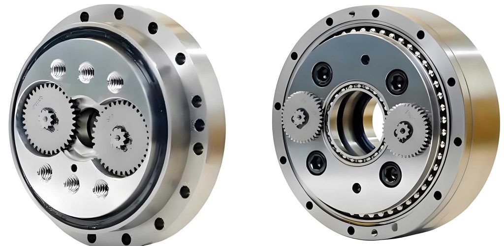
The RV reducer, often referred to as a rotary vector reducer, relies on a cycloidal disc engaging with a pin wheel to achieve speed reduction. The cycloidal gear’s tooth profile must be carefully modified to ensure smooth operation and longevity. Common modification techniques involve adjustments to the equidistance and profile shift, but these methods often rely on empirical values that are kept as trade secrets in factories. In contrast, the new algorithm presented here provides a systematic way to derive the tooth profile coordinates, making it suitable for direct application in CNC machining. This research focuses on optimizing the RV reducer gear profile by dividing it into distinct segments: the tooth root, the working flank, and the tooth tip. Each segment is treated with specific mathematical models to ensure conjugacy in the working region and controlled gaps elsewhere, enhancing the overall performance of the RV reducer.
Conventional Combined Modification Method
The conventional combined modification method for RV reducers typically involves equidistant modification and profile shift modification. This approach aims to create a conjugate meshing condition in the working portion of the tooth profile while leaving gaps in the non-working portions to accommodate lubrication and prevent interference. The process can be broken down into several steps, as outlined below.
Step 1: Parameter Determination – Key parameters include the eccentricity \(a\), the base circle radius of the pin gear \(r_p\), and the roller radius \(r_{rp}\). Additionally, considerations for oil film thickness and backlash must be integrated to ensure proper operation.
Step 2: Calculation of Radial Clearance – The radial clearance \(\Delta j\) is determined by the difference between the equidistant modification amount \(\Delta r_{rp}\) and the profile shift modification amount \(\Delta r_p\), such that \(\Delta r_{rp} – \Delta r_p = \Delta j\). Based on the interference fit between the cycloidal gear and the pin gear, the threshold range for the rotational modification amount \(\delta_c\) is established.
Step 3: Tooth Profile Equation with Rotational Modification – Given the number of pin gear teeth \(Z_p\), eccentricity \(a\), base circle radius \(r_p\), roller radius \(r_{rp}\), and setting \(\delta = \delta_c\), the coordinates of the cycloidal gear with rotational modification are derived as follows:
$$
x_c = \left[ r_p – r_{rp} S^{\frac{1}{2}} \right] \cos\left[(1 – i_H)\phi – \delta\right] – \frac{a r_p}{r_p – Z_b r_{rp} S^{\frac{1}{2}}} \cos\left[i_H \phi’ + \delta\right]
$$
$$
y_c = \left[ r_p – r_{rp} S^{\frac{1}{2}} \right] \sin\left[(1 – i_H)\phi – \delta\right] + \frac{a r_p}{r_p – Z_b r_{rp} S^{\frac{1}{2}}} \sin\left[i_H \phi’ + \delta\right]
$$
where \(i_H\) represents the transmission ratio, defined as \(i_H = Z_b / Z_a\), with \(Z_a\) being the number of teeth on the cycloidal gear. The term \(S\) is calculated as:
$$
S = 1 + k_1^2 – 2k_1 \cos \phi’
$$
and the shortening coefficient \(k_1\) is given by:
$$
k_1 = \frac{a Z_b}{r_p}
$$
Here, \(\phi’\) varies from \(0\) to \(2\pi\) to generate a complete tooth profile.
Step 4: Combined Equidistant and Profile Shift Modification – The final tooth profile equation for the combined modification is expressed as:
$$
x_c’ = \left[ r_p + \Delta r_p – (r_{rp} + \Delta r_{rp}) S_r^{\frac{1}{2}} \right] \cos\left[(1 – i_H)\phi’\right] – \frac{a}{r_p + \Delta r_p} \left[ r_p + \Delta r_p – Z_b (r_{rp} + \Delta r_{rp}) S_r^{\frac{1}{2}} \right] \cos\left[i_H \phi’\right]
$$
$$
y_c’ = \left[ r_p + \Delta r_p – (r_{rp} + \Delta r_{rp}) S_r^{\frac{1}{2}} \right] \sin\left[(1 – i_H)\phi’\right] + \frac{a}{r_p + \Delta r_p} \left[ r_p + \Delta r_p – Z_b (r_{rp} + \Delta r_{rp}) S_r^{\frac{1}{2}} \right] \sin\left[i_H \phi’\right]
$$
where \(S_r^{\frac{1}{2}}\) is computed using:
$$
S_r^{\frac{1}{2}} = \sqrt{1 + k_1’^2 – 2k_1′ \cos \phi’}
$$
and the modified shortening coefficient \(k_1’\) is:
$$
k_1′ = \frac{a Z_b}{r_p + \Delta r_p}
$$
This conventional method ensures that the working flank of the RV reducer gear maintains conjugacy with the pin gear, while gaps are introduced at the tooth root and tip to prevent interference and allow for lubrication.
Example of Conventional Modification
To illustrate the conventional combined modification, consider the RV-60N cycloidal reducer, whose parameters are listed in Table 1. For clarity, the modification amounts are exaggerated by a factor of 100 in the simulation.
| Pin Gear Teeth \(Z_p\) | Eccentricity \(a\) (mm) | Base Circle Radius \(r_p\) (mm) | Roller Radius \(r_{rp}\) (mm) | Equidistant Modification \(\Delta r_{rp}\) (mm) | Profile Shift Modification \(\Delta r_p\) (mm) |
|---|---|---|---|---|---|
| 40 | 1.3 | 136.9798 | 5.99 | 0.036 | -0.026 |
Using MATLAB for simulation, the modified tooth profile and the standard tooth profile are compared. The results show that in the working flank region, the modified profile of the RV reducer maintains a uniform curvature and clearance relative to the standard profile, with gaps at the tooth root and tip. This conforms to the operational requirements and meshing relationships of the RV reducer, ensuring smooth engagement and reduced wear.
A Novel Modification Approach for RV Reducers
The proposed novel modification method for RV reducers deviates from traditional combined techniques by explicitly segmenting the tooth profile based on meshing conditions. The cycloidal gear tooth is divided into three sections: the tooth root (non-working), the working flank, and the tooth tip (non-working). This segmentation allows for precise control over the conjugacy in the working region and the clearance in non-working regions, leveraging cubic spline curves for smooth transitions.
Step 1: Determination of Working Flank Range – The working flank corresponds to the portion of the tooth profile that actively meshes with the pin gear rollers. Based on the pure rolling motion of the generating circle around the base circle, the phase angle \(\phi\) is used to delineate the working and non-working sections. The tooth profile equation in terms of \(\phi\) is given by:
$$
x(\phi) = \frac{r_p \sin \phi – \frac{k_1}{Z_p} \sin(Z_p \phi) + r_{rp} \left( k_1 \sin(Z_p \phi) – \sin \phi \right)}{\sqrt{S}}
$$
$$
y(\phi) = \frac{r_p \cos \phi – \frac{k_1}{Z_p} \cos(Z_p \phi) – r_{rp} \left( k_1 \cos(Z_p \phi) – \cos \phi \right)}{\sqrt{S}}
$$
where \(S = 1 + k_1^2 – 2k_1 \cos(Z_a \phi)\). For the RV-60N reducer, the meshing phase angles for each tooth number are computed, revealing that teeth numbers 4 through 16 exhibit minimal variation in meshing phase angles. Thus, tooth number 4 is identified as the initial meshing tooth, and tooth number 16 as the final meshing tooth, defining the working flank range as \([\phi_4, \phi_{16}]\).
Step 2: Definition of Tooth Root and Tip Curves – The non-working sections, namely the tooth root (AB segment) and tooth tip (CD segment), are modeled using cubic spline curves to ensure smooth connections with the working flank. The endpoints of these segments are determined geometrically, as summarized in Table 2.
| Point | x-coordinate | y-coordinate |
|---|---|---|
| A | 0 | R_{ia} – \Delta |
| B | x(\phi_B) | y(\phi_B) |
| C | x(\phi_C) | y(\phi_C) |
| D | x(\phi_D = \pi / Z_C) | R_{ea} – \Delta |
Here, \(R_{ia}\) is the root circle radius, \(R_{ea}\) is the tip circle radius, and \(\Delta\) represents a clearance allowance. To avoid sharp points and ensure smooth transitions, the first derivatives at points B and C are set to zero. The cubic spline curve for each non-working segment is expressed as:
$$
y = a x^3 + b x^2 + c x + d
$$
For the CD segment, the coefficients \(a, b, c, d\) are solved using the boundary conditions:
$$
y_C = a x_C^3 + b x_C^2 + c x_C + d
$$
$$
y_D = a x_D^3 + b x_D^2 + c x_D + d
$$
$$
\left. \frac{dy}{dx} \right|_{\phi = \phi_C} = 3a x_C^2 + 2b x_C + c = 0
$$
$$
\left. \frac{dy}{dx} \right|_{\phi = \phi_D} = 3a x_D^2 + 2b x_D + c = \frac{dy(\phi_D)/d\phi}{dx(\phi_D)/d\phi}
$$
where the derivatives \(\frac{dy}{dx}\) are computed from the parametric equations. A similar approach is applied to the AB segment. Once the coefficients are determined, the complete tooth profile is assembled by symmetrizing about the tooth slot centerline for the other half of the tooth. The entire gear profile is generated by replicating this single tooth profile around the circumference, accounting for the phase angle shifts.
Step 3: Interference and Smoothness Check – The final step involves verifying that the modified tooth profile of the RV reducer is free from interference, with smooth transitions and no sharp points. If these conditions are met, the profile is ready for implementation in manufacturing.
Example Calculation and Analysis
To validate the novel modification method, the RV-60N cycloidal reducer is used as a case study. The parameters from Table 1 are applied, and the working flank phase angle range is computed as \([\phi_B, \phi_C] = [0.051, 0.291]\) radians. The derivatives at the boundaries are found to be:
$$
\left. \frac{dy}{dx} \right|_B = 0.2543, \quad \left. \frac{dy}{dx} \right|_C = 0.0123
$$
Similarly, for the tooth tip segment:
$$
\left. \frac{dx}{d\phi} \right|_D = -0.0125
$$
Solving the cubic spline equations yields the coefficients for each segment. The complete tooth profile function for the RV reducer is then expressed as a piecewise function:
$$
f(x_n, y_n) = f(r_p, r_{rp}, k_1, Z_p, t_1, t_2, m)
$$
where \(t_1\) ranges from \(0\) to \(x(\phi_B)\), \(t_2\) from \(x(\phi_C)\) to \(x(\phi_D)\), and \(m\) is a sign coefficient (1 for \(\phi = 0\) to \(\pi\), -1 for \(\phi = \pi\) to \(2\pi\)). The specific equations for each segment are as follows.
Tooth Root Segment (AB):
$$
x_1 = (-1)^m t_1
$$
$$
y_1 = -0.002512 ((-1)^m t_1)^3 + 0.012265 ((-1)^m t_1)^2 + 28.25612
$$
$$
x_{1n} = \sin \phi \sqrt{x_1^2 + y_1^2}
$$
$$
y_{1n} = \cos \phi \sqrt{x_1^2 + y_1^2}
$$
Working Flank Segment (BC):
$$
x(i) = \frac{r_p \sin \phi – \frac{k_1}{Z_p} \sin(Z_p \phi) + r_{rp} \left( k_1 \sin(Z_p \phi) – \sin \phi \right)}{\sqrt{S}}
$$
$$
y(i) = \frac{r_p \cos \phi – \frac{k_1}{Z_p} \cos(Z_p \phi) – r_{rp} \left( k_1 \cos(Z_p \phi) – \cos \phi \right)}{\sqrt{S}}
$$
$$
x_n(i) = \sin \phi \sqrt{x(\phi)^2 + y(\phi)^2}
$$
$$
y_n(i) = \cos \phi \sqrt{x(\phi)^2 + y(\phi)^2}
$$
Tooth Tip Segment (CD):
$$
x_2 = (-1)^m t_2
$$
$$
y_2 = -0.002456 ((-1)^m t_2)^3 – 0.0231512 ((-1)^m t_2)^2 + 2.235642 ((-1)^m t_2) + 26.56562
$$
$$
x_{2m} = \sin \phi \sqrt{x_2^2 + y_2^2}
$$
$$
y_{2m} = \cos \phi \sqrt{x_2^2 + y_2^2}
$$
These equations collectively define the optimized tooth profile for the RV reducer. The resulting curve, as simulated, shows a smooth transition between segments, with the working flank maintaining conjugacy and the non-working portions providing controlled clearance. This approach enhances the manufacturability of the RV reducer by providing explicit coordinate data for CNC machining, while also improving performance through precise clearance management.
Discussion on RV Reducer Modification Techniques
The novel modification method presented here offers several advantages over conventional approaches for RV reducers. Firstly, it explicitly segments the tooth profile, allowing for independent control over the working and non-working sections. This segmentation facilitates the use of advanced fitting techniques like cubic splines, which ensure smooth transitions and eliminate sharp points that could lead to stress concentrations. Secondly, the method provides a mathematical framework that can be directly translated into machine code for CNC grinding, aligning with modern manufacturing trends. In contrast, traditional combined modifications often rely on empirical values that may not be optimized for specific applications, and they can result in less predictable clearances.
Moreover, the new algorithm addresses the need for controlled backlash in RV reducers. By defining the non-working sections with cubic splines, the clearance can be precisely adjusted to accommodate lubrication requirements without compromising the conjugacy in the working flank. This is crucial for maintaining the high precision and low backlash that RV reducers are known for in industrial robotics. Additionally, the method’s reliance on phase angle calculations ensures that the working flank is accurately identified based on meshing dynamics, leading to improved load distribution and reduced wear.
From a practical standpoint, the RV reducer benefits from this modification approach because it reduces the dependency on trial-and-error in manufacturing. Factories can implement the derived equations directly, leading to faster production times and higher consistency. The use of cubic splines also allows for flexibility in designing the tooth root and tip shapes, which can be tailored to specific operational conditions, such as high-speed or high-torque applications. Overall, this research contributes to the ongoing optimization of RV reducers, which are critical components in robotics and automation.
Conclusion
In summary, this study introduces a novel gear optimization modification method for RV reducers that segments the tooth profile into working and non-working sections. The working flank is modeled using conjugate meshing principles, while the non-working portions are fitted with cubic spline curves to ensure smooth transitions and controlled clearances. Applied to the RV-60N reducer, the method demonstrates effective results, providing a tooth profile that is both precise and manufacturable. Compared to conventional combined modifications, this approach offers greater control over backlash and facilitates high-accuracy CNC machining, making it a valuable advancement for the production of RV reducers in industrial robotics. Future work could explore the integration of this method with real-time monitoring systems or its extension to other types of precision gears, further enhancing the performance and reliability of RV reducers in demanding applications.