
In the era of industrial智能化, the development of high-end industrial robots has become increasingly critical. Among the core components that drive these robots, the RV reducer stands out as a pivotal transmission element. The RV reducer, short for Rotary Vector reducer, is a high-precision transmission device that evolved from traditional cycloidal pinwheel and planetary gear systems. It is renowned for its large transmission ratio, smooth operation, high accuracy, and reliability, making it indispensable in applications such as automotive, instrumentation, and intelligent robotics. The performance of the RV reducer directly influences the传动精度 of industrial robot joints, underscoring the importance of its design and manufacturing. In this article, I will delve into the传动原理, structural composition, and parametric modeling of the RV reducer, with a focus on its core component—the cycloidal gear pair. Furthermore, I will explore the implementation of rapid prototyping using stereolithography (SLA) technology, highlighting how this approach facilitates the development and testing of RV reducer prototypes. Throughout this discussion, the term RV reducer will be emphasized to reinforce its significance in modern mechanical传动 systems.
The RV reducer is a two-stage closed planetary transmission mechanism that combines involute planetary gear传动 with cycloidal pinwheel planetary传动. This unique design enables it to achieve compactness, high load capacity, and efficient power transmission. The first stage involves an input shaft that transfers rotational motion from an actuator motor to planetary gears, resulting in an initial speed reduction. The second stage utilizes a cycloidal pinwheel system, where the motion is further reduced through the interaction between摆线轮 and针齿. The complexity of the RV reducer lies in the precision required for the cycloidal gear副, as inaccuracies in its geometry can lead to传动平稳性 issues and reduced运动可靠性. Therefore, mastering the parametric modeling of these components is essential for optimizing the overall performance of the RV reducer. This article aims to provide a comprehensive guide on using Autodesk Inventor for parametric design and employing SLA-based 3D printing for rapid prototyping, thereby offering a feasible pathway for the research and development of RV reducer systems.
To understand the RV reducer in depth, it is crucial to first examine its传动原理. The RV reducer operates through a sophisticated mechanism that integrates multiple传动 elements. As illustrated in the structural diagram, the input shaft is directly coupled with a central gear, which meshes with three planetary gears to accomplish the first stage of减速. These planetary gears are connected to crankshafts via splines, transferring eccentric motion to the摆线轮. Two摆线轮 are mounted on the crankshafts with a 180-degree phase difference, engaging with针齿 fixed on the frame. Since the针齿 are stationary, the摆线轮 undergo both公转 (revolution) and反向自转 (reverse rotation). The自转 motion of the摆线轮 is then transmitted through bearings on the crankshafts to the output mechanism, typically a planet carrier, achieving the second stage of减速. This dual-stage process allows the RV reducer to achieve high传动比 while maintaining compact dimensions. The传动比 of the RV reducer can be calculated using the following formula for the overall system:
$$ i = i_1 \times i_2 $$
where \( i_1 \) is the传动比 of the first-stage planetary gear传动, and \( i_2 \) is the传动比 of the second-stage cycloidal pinwheel传动. For the planetary stage, the传动比 is given by:
$$ i_1 = 1 + \frac{z_2}{z_1} $$
where \( z_1 \) is the number of teeth on the central gear, and \( z_2 \) is the number of teeth on the planetary gears. For the cycloidal stage, the传动比 is expressed as:
$$ i_2 = \frac{z_P}{z_P – z_c} $$
where \( z_P \) is the number of针齿, and \( z_c \) is the number of teeth on the摆线轮. In a typical RV reducer, such as the one discussed in this article, the parameters might be \( z_1 = 24 \), \( z_2 = 60 \), \( z_P = 32 \), and \( z_c = 31 \), leading to an overall传动比 of 81. This high传动比 is one of the key advantages of the RV reducer, making it ideal for applications requiring precise motion control in industrial robots.
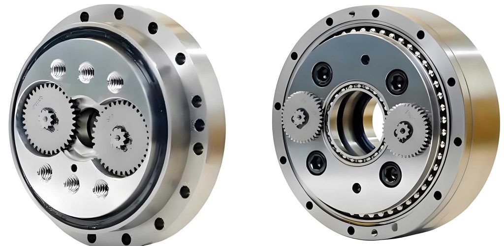
The structural characteristics of the RV reducer contribute significantly to its performance. As shown in the exploded view, the main components include the input shaft, planetary gears, crankshafts,摆线轮,针齿壳,针齿, bearings, output机构, and support flange. The input shaft and central gear are often integrated into a single unit to simplify assembly and enhance rigidity. The crankshafts feature eccentric journals where the摆线轮 are mounted, and their front ends are designed with external splines to transfer torque from the planetary gears. The two摆线轮 are arranged with a 180-degree phase difference to balance radial loads, thereby improving传动平稳性 and reducing vibration. The针齿轮 assembly consists of an inner cycloidal pinwheel shell and multiple针齿, which are fixed to the frame. This configuration ensures that the针齿 remain stationary during operation, allowing the摆线轮 to engage smoothly. The use of high-precision bearings, such as angular contact bearings for axial and radial loads and cylindrical roller bearings for support, further enhances the durability and efficiency of the RV reducer. The compact 2K-V structure of the RV reducer enables it to handle high扭矩 while occupying minimal space, making it a preferred choice for robotic关节 applications.
A critical aspect of designing an RV reducer is the parametric modeling of the cycloidal gear副. The cycloidal gear传动 differs from conventional involute gear传动 in that it involves the啮合 of concave and convex curves, leading to lower contact stress and more uniform wear. Additionally, it avoids issues like根切 and allows for large传动比 even with small齿数. The齿廓曲线 of the摆线轮 is generated based on a specific mathematical equation, which makes traditional modeling methods challenging. Therefore, a parametric approach using software like Autodesk Inventor is highly effective. The standard齿廓 of the摆线轮 is defined as the curve that conjugates with the针齿 without any啮合间隙. The parametric equations for this齿廓 are derived from the geometry of the cycloidal motion. In general, the coordinates of a point on the摆线轮齿廓 can be expressed as:
$$ x_c = \left[ r_p – r_{rp} \Phi^{-1}(K_1, \varphi_1) \right] \cos \left( (1 – i_H) \varphi_1 \right) – \left[ a – K_1 r_{rp} \Phi^{-1}(K_1, \varphi_1) \right] \cos \left( i_H \varphi_1 \right) $$
$$ y_c = \left[ r_p – r_{rp} \Phi^{-1}(K_1, \varphi_1) \right] \sin \left( (1 – i_H) \varphi_1 \right) – \left[ a – K_1 r_{rp} \Phi^{-1}(K_1, \varphi_1) \right] \sin \left( i_H \varphi_1 \right) $$
where \( r_p \) is the radius of the针齿中心圆, \( r_{rp} \) is the radius of the针齿销, \( \varphi_1 \) is the啮合相位角 (the angle of the arm relative to a针齿 center vector), \( i_H \) is the relative传动比 between the摆线轮 and针轮, \( a \) is the偏心距, \( K_1 \) is the短幅系数 given by \( K_1 = a z_p / r_p \), and \( \Phi^{-1}(K_1, \varphi_1) \) is the幅长系数 defined as \( \Phi^{-1}(K_1, \varphi_1) = (1 + K_1^2 – 2K_1 \cos \varphi_1)^{-1/2} \). For practical modeling in Inventor, these equations can be simplified to a more manageable form:
$$ x_c(t) = r_p \left[ \cos \left( \frac{360t}{z_c} \right) – \frac{K_1}{z_P} \cos \left( \frac{z_P}{z_c} \cdot 360t \right) \right] $$
$$ y_c(t) = r_p \left[ \sin \left( \frac{360t}{z_c} \right) – \frac{K_1}{z_P} \sin \left( \frac{z_P}{z_c} \cdot 360t \right) \right] $$
where \( t \) is a parameter ranging from 0 to \( z_c \). Using this simplified equation, the齿廓曲线 can be generated efficiently in Inventor. The process involves creating a new part file, entering the sketch environment, and using the “Expression Curve” tool to input the equations. For instance, with parameters like \( r_p = 154 \) mm, \( a = 4 \) mm, \( z_P = 32 \), and \( z_c = 31 \), we compute \( K_1 = 0.8312 \), and the equations become:
$$ x_c(t) = 154 \left[ \sin \left( \frac{360t}{31} \right) – \frac{0.8312 \times 154}{32} \sin \left( \frac{32}{31} \cdot 360t \right) \right] $$
$$ y_c(t) = 154 \left[ \cos \left( \frac{360t}{31} \right) – \frac{0.8312 \times 154}{32} \cos \left( \frac{32}{31} \cdot 360t \right) \right] $$
for \( t \in (0, 31) \). By输入 these expressions into Inventor, the software generates the precise齿廓曲线, which can then be extruded to create a solid model of the摆线轮. This parametric method allows for easy modifications to design parameters, streamlining the iterative design process for the RV reducer.
To illustrate the key parameters involved in the RV reducer design, the following table summarizes the basic几何 dimensions and传动 characteristics:
| Parameter | Symbol | Value | Description |
|---|---|---|---|
| Transmission Ratio | \( i \) | 81 | Overall reduction ratio of the RV reducer |
| Module | \( m \) | 2 mm | Module of the gears |
| Central Gear Teeth | \( z_1 \) | 24 | Number of teeth on the input central gear |
| Planetary Gear Teeth | \( z_2 \) | 60 | Number of teeth on each planetary gear |
| Pin Gear Teeth | \( z_P \) | 32 | Number of针齿 in the pinwheel |
| Cycloidal Gear Teeth | \( z_c \) | 31 | Number of teeth on each摆线轮 |
| Pin Circle Radius | \( r_p \) | 154 mm | Radius of the针齿中心圆 |
| Eccentricity | \( a \) | 4 mm | Eccentric distance of the crankshaft |
| Short Amplitude Coefficient | \( K_1 \) | 0.8312 | Calculated as \( a z_p / r_p \) |
In addition to the摆线轮, other components of the RV reducer, such as the planetary gears and crankshafts, can be modeled using similar parametric techniques. However, the摆线轮 remains the most complex due to its non-standard齿廓. The use of Inventor’s parametric capabilities ensures that the entire assembly of the RV reducer is accurately represented in a virtual prototype. This virtual model is essential for conducting motion simulations, interference checks, and stress analyses, all of which contribute to the optimization of the RV reducer design. For instance, the crankshaft组件 includes multiple bearings like the 7654B angular contact bearing for handling combined loads, and the N209E cylindrical roller bearing for support. These components are assembled in Inventor to form a complete RV reducer, as shown in the总装 model. This digital prototype serves as a foundation for subsequent physical prototyping via rapid manufacturing techniques.
Once the virtual model of the RV reducer is established, the next step is to create physical prototypes for testing and validation. Traditional manufacturing methods for cycloidal gears, such as插削 or磨削 on specialized machines, are costly and time-consuming, often requiring expensive custom tools. Moreover, achieving high角向精度 between the齿廓 and bearing holes is challenging with these methods. To overcome these limitations, rapid prototyping technologies like stereolithography (SLA) offer a viable alternative. SLA is an additive manufacturing process that uses a laser to cure liquid resin layer by layer, producing highly accurate parts with smooth surface finishes. In this article, I focus on using SLA to fabricate the摆线轮 component of the RV reducer, as it is the most critical and geometrically intricate part. The SLA process not only reduces lead times and costs but also allows for rapid iteration during the design phase of the RV reducer development.
The SLA-based rapid prototyping workflow for the摆线轮 involves several key steps. First, the digital model of the摆线轮, created in Inventor, is exported in the standard STL format, which is widely used in 3D printing. This file is then imported into the slicing software, such as Preform for Formlabs printers, where the model is prepared for printing. The orientation of the part on the build platform is crucial; it affects printing time, surface quality, and the need for support structures. Typically, orienting the model along its smallest dimension minimizes the number of layers and reduces printing time. For the摆线轮, this means placing it such that the axial direction is vertical. Support structures are automatically generated in the software to prevent deformation during printing, especially for overhanging features. These supports are designed as thin, point-like connections that can be easily removed post-processing. The model is then sliced into layers with a specified thickness; for high precision, a layer thickness of 0.025 mm is used, resulting in 315 layers for the摆线轮. This fine resolution ensures that the齿廓曲线 is accurately reproduced. The sliced data is saved in a printer-specific format and uploaded to the SLA printer, such as the Formlabs Form2, which uses a methyl methacrylate photopolymer resin. The printing process takes approximately 2.5 hours, after which the part is carefully removed from the build platform. Post-processing involves washing the part in a solvent like acetone to remove uncured resin, removing support structures, and performing a secondary UV curing step to enhance mechanical properties. The final prototype exhibits excellent dimensional accuracy and surface finish, making it suitable for functional testing in the RV reducer assembly.
To evaluate the effectiveness of SLA for manufacturing RV reducer components, it is important to assess the打印精度 of the produced parts. For the摆线轮, critical tolerances include the圆度 and位置度 of the central bore that interfaces with bearings. Using coordinate measuring machines (CMM), measurements can be taken to verify these parameters. In this case, the圆度 error was found to be less than 0.02 mm, and the位置度 error less than 0.03 mm, both within the design specification of 0.05 mm. This level of精度 ensures that the摆线轮 will fit properly in the RV reducer assembly and function smoothly. Additionally, when assembled into the减速器机壳, the SLA-fabricated摆线轮 operates without issues, demonstrating good装配精度. This validates the use of rapid prototyping for initial prototype development, enabling后续 structural analysis and performance testing without the need for expensive tooling. The table below summarizes the key parameters and outcomes of the SLA process for the摆线轮:
| Aspect | Details |
|---|---|
| 3D Printer | Formlabs Form2 SLA Printer |
| Printing Material | Methyl Methacrylate Photopolymer Resin |
| Layer Thickness | 0.025 mm |
| Number of Layers | 315 |
| Printing Time | 2.5 hours |
| Post-Processing | Acetone wash, support removal, UV curing |
| 圆度 Error | < 0.02 mm |
| 位置度 Error | < 0.03 mm |
| Design Tolerance | < 0.05 mm for both圆度 and位置度 |
The advantages of using SLA for RV reducer prototyping are manifold. Compared to subtractive manufacturing methods, SLA reduces material waste and allows for complex geometries that are difficult to machine. It also accelerates the design cycle by enabling quick iterations based on test feedback. However, it is important to note that SLA parts may have lower mechanical strength than those made from metals, so they are primarily suitable for prototyping and non-load-bearing testing. For functional prototypes under load, alternative materials or post-processing techniques like infiltration can be considered. Nonetheless, for the initial stages of RV reducer development, SLA provides a cost-effective and efficient means to validate designs and conduct preliminary assessments.
In conclusion, the RV reducer is a sophisticated transmission device that plays a crucial role in high-precision applications like industrial robotics. Its design hinges on the accurate modeling of the cycloidal gear副, which can be effectively achieved through parametric methods in software like Autodesk Inventor. By using mathematical equations to define the齿廓曲线, designers can quickly generate and modify geometric models, enhancing flexibility and efficiency in the RV reducer development process. Furthermore, rapid prototyping technologies such as SLA offer a practical approach to creating physical prototypes of complex components like the摆线轮. The SLA process delivers high精度 parts with短 lead times, facilitating early-stage testing and validation. This integrated approach of parametric modeling and rapid prototyping significantly contributes to the advancement of RV reducer technology, enabling faster innovation and improved performance in real-world applications. As the demand for high-performance industrial robots grows, continued research in these areas will be essential for optimizing the design and manufacturing of RV reducers, ensuring they meet the ever-increasing standards of传动精度 and reliability.
To further elaborate on the parametric modeling aspect, it is worth exploring the mathematical foundations of the cycloidal gear equations in more depth. The standard齿廓方程 given earlier is derived from the trochoidal motion of a point on a circle rolling inside another circle. This geometry ensures that multiple teeth are in contact simultaneously, distributing loads evenly and reducing noise. The parameter \( \varphi_1 \) in the equations represents the angular position of the generating point, and its range determines the extent of the齿廓 curve. For a complete tooth, \( \varphi_1 \) typically spans from 0 to \( 2\pi / z_c \), but in the simplified version, the parameter \( t \) is used to iterate over all teeth. The relationship between the design parameters can be optimized to minimize啮合间隙 and maximize传动效率. For instance, the偏心距 \( a \) affects the短幅系数 \( K_1 \), which in turn influences the curvature of the齿廓. Empirical guidelines suggest that for an RV reducer, the first-stage center distance \( a_0 \) should be between 50% and 60% of the针齿中心圆半径 \( r_p \), as expressed by:
$$ 0.5 r_p \leq a_0 \leq 0.6 r_p $$
Additionally, \( r_p \) can be estimated from the output torque \( T \) using the formula:
$$ r_p = (0.85 \sim 1.3) \sqrt[3]{T} $$
These relationships help in initial sizing of the RV reducer components. In the context of parametric modeling, they can be incorporated as constraints in Inventor using parameters and iLogic rules, automating the design process. For example, defining \( r_p \), \( a \), and \( z_P \) as input parameters allows the software to compute \( K_1 \) and generate the齿廓 curve automatically. This dynamic linkage ensures that any changes in the design intent are propagated throughout the model, maintaining consistency and reducing errors. Such capabilities are particularly valuable when designing variants of the RV reducer for different applications, as they save time and effort in re-modeling.
Regarding the rapid prototyping phase, SLA is just one of several additive manufacturing technologies available. Others include fused deposition modeling (FDM), selective laser sintering (SLS), and digital light processing (DLP). Each has its own strengths and limitations in terms of accuracy, material properties, and cost. For the RV reducer, where精度 is paramount, SLA is often preferred due to its fine resolution and smooth surface finish. However, for parts requiring higher strength, SLS with nylon or metal powders might be considered. The choice of technology depends on the specific goals of the prototyping stage. In early concept validation, visual and fit checks may suffice, so SLA is adequate. For functional testing under load, more durable materials are needed. The table below compares common rapid prototyping technologies for RV reducer applications:
| Technology | Materials | Accuracy | Strength | Typical Use in RV Reducer |
|---|---|---|---|---|
| SLA | Photopolymer Resins | High (±0.1 mm) | Moderate | 摆线轮 prototypes, fit testing |
| FDM | PLA, ABS | Medium (±0.2 mm) | Low to Moderate | Non-critical components, housings |
| SLS | Nylon, Metals | High (±0.1 mm) | High | Functional parts under load |
| DLP | Resins | High (±0.05 mm) | Moderate | Detailed models, small features |
In addition to prototyping, additive manufacturing can be used for producing tooling or even end-use parts in some cases. For the RV reducer, this might include custom jigs for assembly or lightweight components for robotic arms. The integration of parametric design with additive manufacturing enables a seamless digital-to-physical workflow, accelerating the product development cycle. This is especially beneficial for the RV reducer industry, where customization and rapid iteration are key to meeting diverse customer needs.
Looking ahead, advancements in both CAD software and 3D printing technology will further enhance the design and manufacturing of RV reducers. For instance, generative design algorithms could be employed to optimize the topology of components like the摆线轮 for weight reduction while maintaining strength. Similarly, multi-material 3D printing could allow for integrated bearings or reinforced sections in a single print. These innovations will push the boundaries of what is possible with RV reducers, making them even more efficient and compact. As a researcher or engineer working on RV reducers, staying abreast of these trends is essential for leveraging the full potential of modern tools and techniques.
In summary, this article has provided a comprehensive overview of the RV reducer, from its传动原理 and structural特点 to parametric modeling and rapid prototyping. By emphasizing the use of mathematical equations and software tools like Inventor, I have shown how precise geometric models can be created efficiently. The application of SLA for prototyping demonstrates a practical approach to validating designs before committing to expensive production methods. The RV reducer, with its complex kinematics and high精度 requirements, benefits greatly from such integrated methodologies. As the field of industrial robotics continues to evolve, the role of the RV reducer will remain central, and ongoing improvements in design and manufacturing will ensure its continued success in powering the machines of the future.