
In the field of precision mechanical transmission, the rotary vector reducer stands as a critical component in robotics, aerospace, and high-precision manufacturing due to its compact design, high torque capacity, and efficiency. As a researcher focused on enhancing the performance of these systems, I have observed that improving transmission accuracy remains a pivotal challenge. The rotary vector reducer’s complex structure, involving multiple stages of gearing and intricate components, makes it susceptible to various error sources, including manufacturing inaccuracies, assembly misalignments, and bearing clearances. These errors, when combined in specific ways, can significantly degrade the dynamic transmission accuracy, leading to reduced system reliability and performance. In this comprehensive study, I aim to delve into the sensitivity of transmission accuracy to different error combination modes in rotary vector reducers. By employing a rigorous mathematical model and advanced sensitivity analysis techniques, I seek to identify the primary error factors and their influence patterns. This analysis will provide valuable insights for designing and manufacturing high-precision rotary vector reducers, ensuring optimal functionality in demanding applications. The rotary vector reducer, with its unique two-stage reduction mechanism, offers an ideal case study for understanding how error interactions affect overall system behavior.
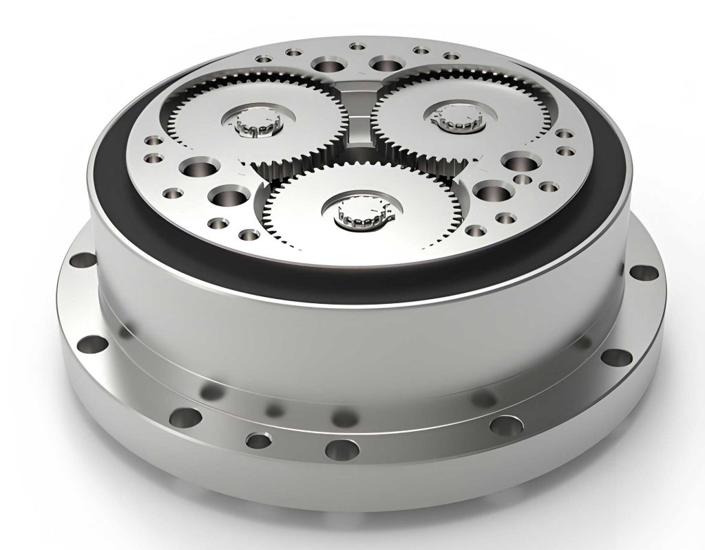
To begin, I will outline the fundamental structure of a typical rotary vector reducer, which consists of a first-stage planetary gear set and a second-stage cycloidal-pin gear mechanism. The first stage includes a sun gear, multiple planetary gears, and a carrier, while the second stage features cycloidal gears, a pin gear, crankshafts, and an output mechanism. This dual-stage design allows for high reduction ratios and compactness, but it also introduces multiple potential error sources. In my research, I focus on a model similar to the RV-80E type, with key parameters such as gear tooth numbers, module, and eccentricity. The dynamic transmission accuracy, defined as the maximum absolute value of instantaneous transmission errors during stable operation, is crucial for assessing performance. Errors in components like the sun gear, planetary gears, cycloidal gears, pin gear, and bearings can combine in various ways, leading to complex effects on output rotation. Understanding these combinations through sensitivity analysis is essential for mitigating their impact. The rotary vector reducer’s reliance on precise meshing and alignment makes it particularly vulnerable to errors, and this study aims to quantify that vulnerability using a systematic approach.
The core of my analysis is a detailed mathematical model for calculating the dynamic transmission accuracy of the rotary vector reducer. This model is based on a mechanical representation that treats supports and meshing stiffnesses as springs, accounting for micro-displacements due to errors and deformations. I consider various error factors, such as base circle eccentricities, tooth profile deviations, assembly misalignments, and bearing clearances, which cause deviations from ideal positions. By applying d’Alembert’s principle, I derive a set of nonlinear differential equations that describe the system’s dynamics. These equations incorporate forces between components, influenced by errors and gaps, and are solved using the nonlinear Newmark method to obtain the actual output angle over time. The instantaneous transmission error, $\theta_{er}$, is calculated as the difference between the actual output angle, $\theta_{ca}$, and the theoretical output angle, $\theta_c$, where $\theta_c$ is derived from the input sun gear angle, $\theta_s$, and the transmission ratio, $N$. Specifically:
$$\theta_{er} = \theta_{ca} – \theta_c$$
$$\theta_c = \frac{\theta_s}{N}$$
The transmission accuracy, $\Delta \theta$, is then defined as the maximum absolute value of $\theta_{er}$ during stable operation:
$$\Delta \theta = \max\{ |\theta_{er}| \}$$
This model allows me to simulate the rotary vector reducer’s behavior under different error conditions, providing a foundation for sensitivity analysis. The equations account for the interactions between the first and second stages, including the planetary gear dynamics and the cycloidal-pin gear engagements. For instance, the stiffness of gear teeth and bearings is modeled using linear spring constants, while errors are introduced as perturbations to ideal geometries. The nonlinearities arise from time-varying meshing conditions and clearance effects, making the system highly sensitive to initial conditions. By solving these equations numerically, I can compute $\Delta \theta$ for various error combinations, enabling a quantitative assessment of their impact. This mathematical framework is essential for understanding how errors propagate through the rotary vector reducer, affecting its overall transmission accuracy.
To analyze the sensitivity of transmission accuracy to error combinations, I adopt a numerical differentiation approach. Sensitivity, in this context, refers to the rate of change of $\Delta \theta$ with respect to each error factor. Given that the transmission accuracy function, $f(\mathbf{x})$, depends on a vector of error variables $\mathbf{x} = [x_1, x_2, \dots, x_k]$ (e.g., manufacturing tolerances and clearances), the sensitivity vector $\mathbf{S}$ is defined as the gradient:
$$\mathbf{S} = \nabla f = \left[ \frac{\partial f}{\partial x_1}, \frac{\partial f}{\partial x_2}, \dots, \frac{\partial f}{\partial x_k} \right] = [S_1, S_2, \dots, S_k]$$
Since $f(\mathbf{x})$ is obtained from numerical simulations rather than an analytical expression, I approximate the partial derivatives using finite differences. For each error variable $x_i$, the sensitivity $S_i$ is computed as:
$$S_i = \frac{f(\mathbf{x} + \Delta x_i \cdot \mathbf{e}_i) – f(\mathbf{x})}{\Delta x_i} \quad \text{for } i = 1, 2, \dots, k$$
where $\mathbf{e}_i$ is a unit vector in the direction of $x_i$, and $\Delta x_i$ is a small perturbation. To enhance accuracy, I use a five-point interpolation numerical differentiation method. This involves dividing the error range into multiple data points, fitting a Lagrange polynomial to groups of five points, and computing the derivative at the central point. Specifically, for $n = 101$ data points over a range (e.g., 0 to 50 μm), I group them into 97 sets of five adjacent points. For each set, I apply Lagrange interpolation to estimate the derivative at the third point, resulting in a smooth sensitivity curve. This method reduces numerical noise and provides reliable sensitivity values for each error combination mode in the rotary vector reducer. The sensitivity analysis helps identify which errors have the most significant effect on transmission accuracy, guiding prioritization in manufacturing and assembly processes.
In my study, I consider a wide array of error combination modes for the rotary vector reducer, categorized into first-stage errors, second-stage errors, and bearing clearances. Each mode represents a specific configuration of errors across components, such as synchronous or anti-phase deviations between dual cycloidal gears. To organize these modes, I use tables that summarize the error types, symbols, and descriptions. For instance, first-stage errors include the sun gear’s assembly error ($A_S$), base circle eccentricity ($E_S$), and planetary gear base circle eccentricity ($E_P$). Second-stage errors encompass cycloidal gear tooth slot deviations ($R_D$), pitch cumulative errors ($A_{PD}$), crankshaft hole eccentricities ($E_{DH}$), pin gear tooth slot deviations ($R_I$), pitch cumulative errors ($A_{PI}$), eccentric cam errors ($E_C$), and planetary carrier assembly errors ($E_{CH}$). Bearing clearances involve gaps between cycloidal gears and crankshafts ($C_{DC}$), between the planetary carrier and crankshafts ($C_{CC}$), and between the planetary carrier and frame ($C_{CA}$). For sensitivity computation, I vary each error magnitude $p$ from 0 to 50 μm, simulating the transmission accuracy $\Delta \theta$ across this range. The results are plotted as $\Delta \theta$ versus $p$ curves, from which sensitivity curves are derived using the five-point method. This systematic approach allows me to compare the impact of different error combinations on the rotary vector reducer’s performance.
Below, I present tables summarizing the error combination modes and their corresponding sensitivity values. These tables are derived from extensive simulations and highlight the key findings. First, Table 1 lists the basic structural parameters of the rotary vector reducer used in this analysis, based on the RV-80E model. This provides context for the mathematical model and error ranges.
| Parameter | First Stage | Second Stage |
|---|---|---|
| Transmission Ratio | 81 | – |
| Sun Gear Teeth | 16 | – |
| Planetary Gear Teeth | 32 | – |
| Module (mm) | 1.75 | – |
| Pressure Angle (°) | 20 | – |
| Cycloidal Gear Teeth | – | 39 |
| Pin Gear Teeth | – | 40 |
| Eccentricity (mm) | – | 1.5 |
| Pin Radius (mm) | – | 3 |
Next, Table 2 outlines the error combination modes for the first-stage components. These errors are relatively simple but set the stage for more complex interactions in the rotary vector reducer.
| Error Symbol | Description | Combination Mode |
|---|---|---|
| $A_S$ | Sun gear assembly error | Uniform error across all planets |
| $E_S$ | Sun gear base circle eccentricity | Single eccentricity component |
| $E_P$ | Planetary gear base circle eccentricity | Identical errors on all planets |
For the second-stage, errors are more diverse due to the dual cycloidal gears and multiple crankshafts. Table 3 categorizes cycloidal gear-related errors, including tooth slot deviations and pitch cumulative errors, with modes indicating phase relationships between the two gears.
| Error Symbol | Description | Combination Mode |
|---|---|---|
| $R_{D-1}$ | Cycloidal gear tooth slot deviation (1st order) | In-phase between gears |
| $R_{D-2}$ | Cycloidal gear tooth slot deviation (1st order) | Anti-phase between gears |
| $R_{D-3}$ | Cycloidal gear tooth slot deviation (2nd order) | In-phase between gears |
| $R_{D-4}$ | Cycloidal gear tooth slot deviation (2nd order) | Anti-phase between gears |
| $A_{PD-1}$ | Cycloidal gear pitch cumulative error (1st order) | In-phase between gears |
| $A_{PD-2}$ | Cycloidal gear pitch cumulative error (1st order) | Anti-phase between gears |
| $A_{PD-3}$ | Cycloidal gear pitch cumulative error (2nd order) | In-phase between gears |
| $A_{PD-4}$ | Cycloidal gear pitch cumulative error (2nd order) | Anti-phase between gears |
Table 4 focuses on crankshaft hole eccentricities in the cycloidal gears, which are critical for aligning the second stage in the rotary vector reducer.
| Error Symbol | Description | Combination Mode |
|---|---|---|
| $E_{DH-1}$ | Crankshaft hole eccentricity in cycloidal gear | Uniform direction on both gears |
| $E_{DH-2}$ | Crankshaft hole eccentricity in cycloidal gear | Opposite directions on gears |
| $E_{DH-3}$ | Crankshaft hole eccentricity in cycloidal gear | Radial misalignment |
Pin gear errors, as shown in Table 5, include tooth slot deviations and pitch cumulative errors, with first and second-order components affecting the rotary vector reducer’s meshing.
| Error Symbol | Description | Combination Mode |
|---|---|---|
| $R_{I-1}$ | Pin gear tooth slot deviation (1st order) | Uniform around circumference |
| $R_{I-2}$ | Pin gear tooth slot deviation (2nd order) | Uniform around circumference |
| $A_{PI-1}$ | Pin gear pitch cumulative error (1st order) | Uniform around circumference |
| $A_{PI-2}$ | Pin gear pitch cumulative error (2nd order) | Uniform around circumference |
Eccentric cam errors on the crankshafts are detailed in Table 6, highlighting various phase relationships among the three cams in the rotary vector reducer.
| Error Symbol | Description | Combination Mode |
|---|---|---|
| $E_{C-1}$ | Eccentric cam error on crankshaft | All cams in same direction |
| $E_{C-2}$ | Eccentric cam error on crankshaft | Two cams in phase, one anti-phase |
| $E_{C-3}$ | Eccentric cam error on crankshaft | Asymmetric distribution |
Bearing clearance combinations, crucial for the rotary vector reducer’s dynamics, are summarized in Table 7, covering gaps at different interfaces.
| Error Symbol | Description | Combination Mode |
|---|---|---|
| $C_{DC-1}$ | Clearance between cycloidal gear and crankshaft | Uniform on all crankshafts |
| $C_{DC-2}$ | Clearance between cycloidal gear and crankshaft | Variable across crankshafts |
| $C_{CC-1}$ | Clearance between planetary carrier and crankshaft | Uniform on all crankshafts |
| $C_{CC-2}$ | Clearance between planetary carrier and crankshaft | Variable across crankshafts |
| $C_{CA}$ | Clearance between planetary carrier and frame | Single clearance value |
After simulating these error combination modes, I compute the sensitivity values for each, presented in Table 8. This table consolidates the key results, showing how sensitive the transmission accuracy of the rotary vector reducer is to various errors. Only modes with sensitivity $S \geq 0.1$ arcseconds per micrometer are included, as lower values indicate negligible impact.
| Error Combination Symbol | Sensitivity $S$ (″/μm) | Description |
|---|---|---|
| $R_{D-1}$ | 1.153 | Cycloidal gear tooth slot deviation (1st order, in-phase) |
| $R_{D-2}$ | 0.451 | Cycloidal gear tooth slot deviation (1st order, anti-phase) |
| $R_{D-3}$ | 2.312 | Cycloidal gear tooth slot deviation (2nd order, in-phase) |
| $R_{D-4}$ | 1.518 | Cycloidal gear tooth slot deviation (2nd order, anti-phase) |
| $R_{D-5}$ | 1.058 | Cycloidal gear tooth slot deviation (2nd order, asymmetric) |
| $R_{D-6}$ | 0.182 | Cycloidal gear tooth slot deviation (2nd order, symmetric) |
| $A_{PD-1}$ | 0.644 | Cycloidal gear pitch cumulative error (1st order, in-phase) |
| $A_{PD-2}$ | 0.497 | Cycloidal gear pitch cumulative error (1st order, anti-phase) |
| $A_{PD-3}$ | 1.251 | Cycloidal gear pitch cumulative error (2nd order, in-phase) |
| $A_{PD-4}$ | 0.843 | Cycloidal gear pitch cumulative error (2nd order, anti-phase) |
| $E_{DH-1}$ | 1.672 | Crankshaft hole eccentricity (uniform direction) |
| $E_{DH-3}$ | 3.344 | Crankshaft hole eccentricity (opposite directions) |
| $E_{DH-6}$ | 0.549 | Crankshaft hole eccentricity (radial misalignment) |
| $E_{DH-8}$ | 1.101 | Crankshaft hole eccentricity (asymmetric) |
| $R_{I-1}$ | 0.535 | Pin gear tooth slot deviation (1st order) |
| $R_{I-2}$ | 1.035 | Pin gear tooth slot deviation (2nd order) |
| $A_{PI-1}$ | 0.345 | Pin gear pitch cumulative error (1st order) |
| $A_{PI-2}$ | 0.635 | Pin gear pitch cumulative error (2nd order) |
| $E_{C-1}$ | 0.786 | Eccentric cam error (all same direction) |
| $E_{C-3}$ | 1.566 | Eccentric cam error (asymmetric distribution) |
| $E_{C-7}$ | 0.770 | Eccentric cam error (partial anti-phase) |
| $E_{C-8}$ | 0.802 | Eccentric cam error (variable phase) |
| $E_{C-9}$ | 1.371 | Eccentric cam error (complex combination) |
| $C_{DC-1}$ | 1.846 | Bearing clearance: cycloidal gear-crankshaft (uniform) |
| $C_{DC-2}$ | 2.103 | Bearing clearance: cycloidal gear-crankshaft (variable) |
| $C_{DC-3}$ | 1.646 | Bearing clearance: cycloidal gear-crankshaft (asymmetric) |
| $C_{DC-4}$ | 2.333 | Bearing clearance: cycloidal gear-crankshaft (high variability) |
| $C_{DC-5}$ | 2.776 | Bearing clearance: cycloidal gear-crankshaft (maximum impact) |
| $C_{DC-6}$ | 2.459 | Bearing clearance: cycloidal gear-crankshaft (moderate variability) |
| $C_{DC-7}$ | 1.997 | Bearing clearance: cycloidal gear-crankshaft (low uniformity) |
| $C_{DC-8}$ | 2.034 | Bearing clearance: cycloidal gear-crankshaft (mixed modes) |
| $C_{DC-9}$ | 1.472 | Bearing clearance: cycloidal gear-crankshaft (minimal effect) |
| $C_{CC-1}$ | 2.408 | Bearing clearance: planetary carrier-crankshaft (uniform) |
| $C_{CC-2}$ | 2.876 | Bearing clearance: planetary carrier-crankshaft (variable) |
| $C_{CC-3}$ | 2.354 | Bearing clearance: planetary carrier-crankshaft (asymmetric) |
From the sensitivity results, I can draw several key insights regarding the rotary vector reducer’s transmission accuracy. First, the first-stage errors, such as $A_S$, $E_S$, and $E_P$, exhibit sensitivity values below 0.1 ″/μm, indicating their negligible impact on transmission accuracy. This is because the first stage primarily serves as a speed reducer with relatively simple gear interactions, and errors here are attenuated by the second stage. In contrast, second-stage errors show significant sensitivity, heavily dependent on their combination modes. For cycloidal gear errors, such as tooth slot deviations and pitch cumulative errors, the phase relationship between the two gears is crucial. When first-order errors are in anti-phase (e.g., $R_{D-2}$), sensitivity is lower (0.451 ″/μm) because the errors cancel out due to the 180° installation offset. However, for second-order errors in phase (e.g., $R_{D-3}$), sensitivity is high (2.312 ″/μm) as errors叠加. Similarly, crankshaft hole eccentricities have high sensitivity when in opposite directions ($E_{DH-3}$ at 3.344 ″/μm), suggesting that simultaneous machining of these holes can improve accuracy by ensuring uniformity. Pin gear errors show higher sensitivity for second-order components ($R_{I-2}$ at 1.035 ″/μm) than first-order, due to the additive effect across cycloidal gears. Eccentric cam errors are most sensitive in asymmetric combinations ($E_{C-3}$ at 1.566 ″/μm), emphasizing the need for balanced cam alignment in the rotary vector reducer.
Bearing clearances, however, emerge as the most critical factor affecting the rotary vector reducer’s transmission accuracy. The clearance between the planetary carrier and crankshafts ($C_{CC-2}$) has the highest sensitivity at 2.876 ″/μm, followed closely by cycloidal gear-crankshaft clearances (e.g., $C_{DC-5}$ at 2.776 ″/μm). These clearances introduce nonlinearities and backlash, directly impacting the meshing precision between cycloidal gears and the pin gear. The sensitivity curves for these modes are approximately linear, as seen in plots of $\Delta \theta$ versus $p$, confirming a direct proportionality between error magnitude and transmission accuracy degradation. In contrast, the clearance between the planetary carrier and frame ($C_{CA}$) has sensitivity below 0.1 ″/μm, indicating minimal effect. This analysis underscores that in designing a high-precision rotary vector reducer, reducing or eliminating bearing clearances at key interfaces should be a priority, alongside controlling second-stage error phases. The mathematical model supports these findings, with the differential equations highlighting how clearance-induced forces alter dynamic responses.
To further illustrate the linear relationship, consider the sensitivity formula in the context of the rotary vector reducer. For an error combination mode with sensitivity $S$, the change in transmission accuracy, $\Delta \Delta \theta$, for a small error change $\Delta p$ can be approximated as:
$$\Delta \Delta \theta \approx S \cdot \Delta p$$
This linear approximation holds for error ranges up to 50 μm, as validated by the near-straight lines in the $\Delta \theta$-$p$ plots. For instance, with $S = 2.876$ ″/μm for $C_{CC-2}$, a 10 μm increase in clearance leads to roughly 28.76 arcseconds of additional transmission error. Such quantifiable relationships enable designers to set tolerance limits for the rotary vector reducer. Additionally, the overall transmission error can be expressed as a sum of contributions from individual error modes, though interactions may cause nonlinearities. A simplified representation is:
$$\Delta \theta \approx \sum_{i=1}^{k} S_i \cdot p_i + \text{interaction terms}$$
where $p_i$ is the magnitude of the $i$-th error. In practice, the interaction terms are small for most combinations, justifying the focus on individual sensitivities. This formulation aids in optimizing the rotary vector reducer by allocating resources to reduce high-sensitivity errors first.
In conclusion, my sensitivity analysis of error combination modes on transmission accuracy in rotary vector reducers reveals that second-stage errors and bearing clearances are the dominant factors, with sensitivities often exceeding 1 ″/μm. The phase relationships between dual cycloidal gears, such as anti-phase for first-order errors and in-phase for second-order errors, significantly influence sensitivity values. Bearing clearances, particularly at the planetary carrier-crankshaft and cycloidal gear-crankshaft interfaces, show the highest sensitivities, underscoring the need for precision in assembly and component manufacturing. First-stage errors have minimal impact, allowing for relaxed tolerances in those areas. These findings provide a theoretical basis for enhancing the design and manufacturing of rotary vector reducers, guiding engineers to focus on critical error sources and combination modes. Future work could explore advanced sensitivity methods, such as adjoint-based approaches, or extend the analysis to other reducer types. By implementing the insights from this study, manufacturers can produce rotary vector reducers with improved transmission accuracy, ensuring reliable performance in robotics and other high-precision applications. The rotary vector reducer, as a complex mechanical system, benefits greatly from such detailed error analysis, paving the way for next-generation precision transmission solutions.