
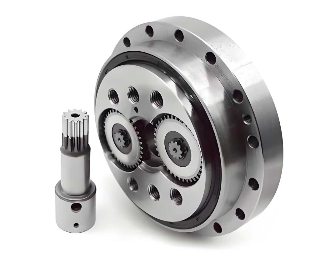
In the field of industrial robotics, precision and reliability are paramount, and the RV reducer plays a critical role as a high-precision component in robot joints. The RV reducer is renowned for its compact structure, high transmission ratio, and excellent rigidity, making it indispensable for applications requiring accurate motion control. The transmission system of the RV reducer consists of two stages: the first stage involves involute planetary gear transmission, and the second stage features cycloidal pinion transmission. Among these, the cycloidal pinion transmission is particularly significant because it directly influences the overall transmission accuracy due to its connection to the output shaft. This meshing system operates with multiple teeth in contact, which enhances load capacity and efficiency, but its performance is highly dependent on factors such as tooth profile modification, initial clearance, and elastic deformations under load. Therefore, a thorough analysis of the meshing characteristics of the cycloidal pinion transmission in the RV reducer is essential for optimizing design and ensuring operational reliability.
The cycloidal pinion transmission in the RV reducer typically employs a standard cycloidal wheel system, but this may not compensate for manufacturing errors or facilitate optimal lubrication. Hence, tooth profile modifications are commonly applied to the cycloidal wheel. The primary modification methods include equidistant modification, shift modification, and rotational modification. These adjustments alter the tooth geometry to improve meshing performance and reduce wear. The general equation for the modified cycloidal tooth profile, considering these modifications, can be expressed as follows:
$$x = (r_p – \Delta r_p) \sin(\psi_i – \varphi) – (a – \Delta a) \sin(z_c \psi_i) + \Delta r_r \sin(\psi_i – \varphi – \alpha)$$
$$y = (r_p – \Delta r_p) \cos(\psi_i – \varphi) – (a – \Delta a) \cos(z_c \psi_i) + \Delta r_r \cos(\psi_i – \varphi – \alpha)$$
where $$r_p$$ is the radius of the pin tooth center circle (in mm), $$\Delta r_p$$ is the equidistant modification amount (in mm), $$a$$ is the eccentricity (in mm), $$\Delta a$$ is the shift modification amount (in mm), $$z_c$$ is the number of pin teeth, $$z_b$$ is the number of cycloidal wheel teeth, $$\psi_i$$ is the angle of the pin tooth relative to the initial meshing pin tooth (in degrees), $$\varphi$$ is the rotational modification amount (in degrees), and $$\alpha$$ is a parameter defined as $$\alpha = \arctan(\frac{\Delta a}{r_p})$$. The short-range coefficient $$K$$ is given by $$K = \frac{a z_c}{r_p}$$. These modifications ensure that the cycloidal wheel can accommodate assembly tolerances and enhance the lubrication conditions, which are crucial for the longevity of the RV reducer.
After modification, the cycloidal wheel does not achieve full-tooth contact during meshing; instead, initial clearances exist between the cycloidal teeth and pin teeth when one pair is in contact. The initial clearance along the normal direction for the i-th tooth pair can be derived based on the tooth profile equations. The formula for the initial clearance $$\Delta_i$$ is:
$$\Delta_i = r_p \left(1 – \sqrt{1 + \left(\frac{K}{z_c}\right)^2 – 2\frac{K}{z_c} \cos(\psi_i)}\right) – \Delta r_p – \Delta a \cos(\psi_i)$$
where $$\psi_i$$ ranges from $$-\pi/z_c$$ to $$\pi/z_c$$. This initial clearance distribution is critical because it determines which teeth will engage under load. By setting the derivative of $$\Delta_i$$ with respect to $$\psi_i$$ to zero, we can find the points of minimum clearance, which correspond to the most likely engagement positions. The distribution curve of $$\Delta_i$$ versus $$\psi_i$$ shows that clearances vary symmetrically around the initial meshing point, influencing the number of teeth in simultaneous contact. Understanding this clearance is vital for predicting the load distribution and stress patterns in the RV reducer’s cycloidal transmission.
The determination of the number of simultaneously meshing teeth in the cycloidal pinion transmission of the RV reducer is based on the principle that only teeth where the total deformation along the common normal direction exceeds the initial clearance will engage under load. When torque is applied, the cycloidal wheel and pin teeth undergo deformations, including contact deformation of the cycloidal wheel and bending deformation of the pin teeth. The total deformation $$\delta_i$$ at the i-th tooth along the common normal direction is given by:
$$\delta_i = l_i \beta \quad (i = 1, 2, \ldots, z_b/2)$$
where $$l_i$$ is the distance from the meshing point of the i-th pin tooth to the center of the cycloidal wheel $$O_c$$ along the common normal, and $$\beta$$ is the rotational angle of the cycloidal wheel due to deformation under load. The distance $$l_i$$ can be calculated as:
$$l_i = r_c \cos(\theta_i)$$
Here, $$r_c$$ is the pitch radius of the cycloidal wheel, and $$\theta_i$$ is the angle between the common normal at the i-th meshing point and the line $$O_c O_p$$, where $$O_p$$ is the center of the pin tooth circle. The deformation $$\beta$$ is derived from the contact and bending deformations at the most heavily loaded tooth pair, typically near the position where $$\psi_i = 0$$. The contact deformation $$w$$ and bending deformation $$f$$ are approximated using Hertzian contact theory and beam theory, respectively. For the maximum loaded tooth, the contact deformation is:
$$w = \frac{2(1 – \nu^2)}{\pi E} \frac{P}{b} \ln\left(\frac{4R}{b}\right)$$
where $$\nu$$ is Poisson’s ratio, $$E$$ is the elastic modulus, $$P$$ is the contact load, $$b$$ is the width of the cycloidal wheel, and $$R$$ is the radius of curvature at the meshing point. The bending deformation of the pin tooth is often negligible compared to the contact deformation for typical RV reducer designs. By equating the total deformation $$\delta_i$$ to the initial clearance $$\Delta_i$$, we can solve for the engagement condition. Teeth where $$\delta_i > \Delta_i$$ will participate in meshing, and the range of $$\psi_i$$ where this inequality holds defines the number of simultaneously meshing teeth. This theoretical analysis provides a foundation for simulating and optimizing the RV reducer’s performance.
To validate the theoretical models and gain deeper insights into the meshing behavior of the RV reducer’s cycloidal pinion transmission, we conducted static simulation analyses using ANSYS software. The RV reducer model, specifically an RV-20E type, was constructed in SOLIDWORKS and then imported into ANSYS for finite element analysis. Features such as fillets and bolt holes were omitted to simplify the mesh and reduce computational complexity, focusing on the essential geometry of the cycloidal wheel and pin teeth. The key structural and material parameters are summarized in the following tables:
| Parameter Name | Value | Parameter Name | Value |
|---|---|---|---|
| Pin tooth center circle diameter (mm) | 104.3 | Pressure angle (degrees) | 20 |
| Pin tooth diameter (mm) | 4 | Equidistant modification amount (mm) | -0.01 |
| Eccentricity (mm) | 0.9 | Shift modification amount (mm) | -0.012 |
| Number of cycloidal wheel teeth | 39 | Cycloidal wheel width (mm) | 8 |
| Input sun gear teeth number | 12 | First-stage transmission modification coefficient sum | 0.35526 |
| Planet gear teeth number | 24 | First-stage transmission center distance (mm) | 27.5 |
| Module (mm) | 1.5 |
| Component | Material | Density (kg/mm³) | Elastic Modulus (MPa) | Poisson’s Ratio |
|---|---|---|---|---|
| Input shaft | 15CrMo | 7.88×10⁻⁶ | 2.12×10⁵ | 0.284 |
| Planet gear | 38CrMoAl | 7.85×10⁻⁶ | 2.11×10⁵ | 0.277 |
| Crankshaft | 20CrMo | 7.82×10⁻⁶ | 2.11×10⁵ | 0.292 |
| Cycloidal wheel | GCr15 | 7.83×10⁻⁶ | 2.19×10⁵ | 0.3 |
| Pin tooth | GCr15 | 7.83×10⁻⁶ | 2.19×10⁵ | 0.3 |
| Other parts | 45 steel | 7.89×10⁻⁶ | 2.09×10⁵ | 0.269 |
The meshing of the model was carefully performed, with a focus on the contact regions between the cycloidal wheel and pin teeth. We applied a rotational load at the input shaft, simulating different torque conditions to observe the meshing characteristics. The loads were set at 80 N·m, 110 N·m, 140 N·m, 170 N·m, 200 N·m, and 230 N·m, representing a range of operational scenarios for the RV reducer. The simulation involved a transient analysis with 10 load steps over a full rotation of 360 degrees. One cycloidal wheel was retained in the model to simplify the analysis, while ensuring that the results reflect the behavior of the actual system where two cycloidal wheels are typically phased 180 degrees apart.
The simulation results revealed that under all tested load conditions, the number of simultaneously meshing teeth on a single cycloidal wheel remained constant at 5. This indicates that for the entire RV reducer with two cycloidal wheels, the total number of meshing teeth is 10, assuming ideal phasing. The contact stress distributions varied with load, as shown in the stress contour plots extracted from ANSYS. Notably, the maximum contact stress did not occur at the center of the meshing zone but was slightly offset, which aligns with theoretical predictions due to the initial clearances and tooth modifications. The following table summarizes the contact stress trends and meshing behavior:
| Load (N·m) | Number of Meshing Teeth per Cycloidal Wheel | Maximum Contact Stress (MPa) | Observations |
|---|---|---|---|
| 80 | 5 | Approx. 250 | Stress concentration near engagement points |
| 110 | 5 | Approx. 300 | Increased stress with load, stable meshing |
| 140 | 5 | Approx. 350 | Uniform stress distribution across teeth |
| 170 | 5 | Approx. 400 | Further stress rise, no change in tooth count |
| 200 | 5 | Approx. 450 | High stress, but meshing remains stable |
| 230 | 5 | Approx. 500 | Peak stress, yet tooth count constant |
Analysis of the contact stress over time showed distinct phases. During the initial 0 to 0.5 seconds, the contact stress was similar across different loads, rapidly reaching a steady state. From 0.5 to 7 seconds, the contact stress increased with load, but higher loads resulted in more stable stress values. From 7 to 8 seconds, as the rotation progressed, the contact stress decreased for lower loads and increased more rapidly for higher loads. This behavior underscores the dynamic nature of meshing in the RV reducer, where load variations impact stress cycles and potential fatigue life. Additionally, examining a single cycloidal tooth revealed that contact stress initially rises sharply upon engagement, peaks, and then gradually declines as the tooth disengages. Along the tooth width direction, the contact stress exhibited a gradual increase from the outer edges toward the center, indicating that load distribution is not uniform and may require further optimization for wear resistance.
To complement the simulation findings, we performed numerical analysis using MATLAB to calculate the number of meshing teeth and maximum contact loads under different torque conditions. The approach is based on the principle that teeth engage when the total deformation exceeds the initial clearance. The maximum contact load $$P_{\text{max}}$$ for the most heavily loaded tooth pair is given by:
$$P_{\text{max}} = \frac{T_c}{\sum_{i=1}^{n} l_i \cos(\theta_i)}$$
where $$T_c$$ is the torque acting on a single cycloidal wheel, approximated as $$T_c = 0.55T$$ to account for manufacturing errors and structural asymmetries, with $$T$$ being the output torque. The distance $$l_i$$ and angle $$\theta_i$$ are derived from the geometry and deformation models. We implemented a computational flowchart in MATLAB to iterate through different torque values and solve for the engagement conditions. The flowchart involves calculating the initial clearance $$\Delta_i$$ and total deformation $$\delta_i$$ for each tooth, comparing them to determine which teeth are in contact, and then summing the loads to find $$P_{\text{max}}$$ and the number of meshing teeth. The results from this numerical analysis are presented below:
| Torque (N·m) | Maximum Contact Load (N) | Number of Meshing Tooth Pairs |
|---|---|---|
| 80 | 407.39 | 5 |
| 110 | 455.11 | 5 |
| 140 | 498.10 | 5 |
| 170 | 543.43 | 5 |
| 200 | 603.19 | 5 |
| 230 | 650.40 | 5 |
The MATLAB results confirm the ANSYS simulation outcomes, showing that the number of simultaneously meshing teeth remains 5 across the torque range, while the maximum contact load increases with torque. This consistency validates the theoretical models and demonstrates the robustness of the cycloidal pinion transmission in the RV reducer under varying operational conditions. The close agreement between simulation and numerical analysis provides confidence in using these methods for future design optimizations of RV reducers.
In conclusion, our comprehensive analysis of the cycloidal pinion transmission in the RV reducer highlights several key insights. First, the number of simultaneously meshing teeth is stable at 5 per cycloidal wheel for loads above 80 N·m, indicating that the meshing system reaches a saturation point where additional load does not engage more teeth but rather increases stress on the existing contacts. This finding is crucial for designing RV reducers with adequate load capacity and longevity. Second, the contact stress behavior is dynamic, with phases of rapid stabilization, load-dependent variations, and end-of-cycle changes, suggesting that fatigue analysis should consider these transients. Third, the tooth width direction shows a non-uniform stress distribution, pointing to potential areas for geometric refinements to enhance wear resistance. Fourth, the combination of ANSYS simulations and MATLAB numerical analysis provides a reliable framework for predicting meshing characteristics, which can be extended to other RV reducer configurations or similar gear systems. Overall, this study underscores the importance of considering tooth profile modifications, initial clearances, and elastic deformations in the design and analysis of RV reducers, contributing to improved performance and reliability in industrial robotics applications.
The RV reducer’s cycloidal pinion transmission is a complex yet vital component, and our work demonstrates that through detailed modeling and simulation, we can gain a deeper understanding of its meshing behavior. Future research could explore the effects of temperature variations, lubrication conditions, and long-term wear on the meshing characteristics, further enhancing the durability and efficiency of RV reducers. By continuously refining these analyses, we can support the advancement of high-precision robotics and automation technologies where the RV reducer plays a pivotal role.