
In the evolution of robotic systems, the wrist actuator plays a pivotal role in enhancing dexterity and functionality. As I delve into this topic, I aim to explore a novel flexible wrist design based on spherical gear transmission, which offers significant advantages such as simplicity, compactness, and a large range of motion. This wrist is particularly suitable for applications like spray painting and welding robots, capable of producing 260 degrees of pitch and yaw motion along with continuous bidirectional roll rotation. Throughout this article, I will emphasize the core concept of the spherical gear, detailing its meshing principles, the wrist’s operational mechanics, and a comprehensive kinematic analysis. To enrich the discussion, I will incorporate tables and mathematical formulations, ensuring a thorough understanding of the subject.
The development of robotic wrists has seen remarkable progress since the early days of remote manipulation. Initial designs, such as the 3-axis remote wrist, were limited in flexibility, but subsequent innovations, like the RPY (Roll-Pitch-Yaw) wrist, paved the way for more agile systems. Among these, flexible wrists have garnered attention for their ability to mimic human-like motion, with the spherical gear-based variant standing out due to its unique transmission mechanism. The spherical gear, a key component here, transforms planar gear kinematics into a spherical domain, enabling multi-axis rotations. This article will first elucidate the meshing principles of spherical gears, then describe the wrist’s structure and action, and finally provide an in-depth kinematic analysis, including forward and inverse solutions for both pitching-yawing and rolling motions.
To visualize the spherical gear mechanism, consider the following illustration, which depicts the installation and interaction of spherical gears in a cross-frame setup. This setup is fundamental to the wrist’s operation, as it allows for pure rolling motion between spherical surfaces, facilitating wide-angle deflections.
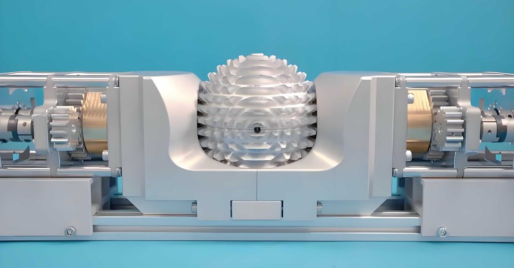
The meshing principle of spherical gears is rooted in converting planar gear pairs into spherical counterparts. Imagine a pair of standard spur gears rotating around their central axis, which is termed the polar axis. By revolving this pair around the polar axis through a full circle, we obtain two spherical gears. From one end of the polar axis, a single spherical gear appears as concentric rings of teeth distributed over a spherical surface, akin to lunar craters. When meshed, these spherical gears engage such that one pitch sphere rolls purely over another, permitting the polar axes to deflect in all directions relative to each other. This unique property stems from the fact that during meshing, only the sphere centers remain fixed, while the spheres themselves can rotate about the X and Y axes in a Cartesian coordinate system. Consequently, spherical gears must be mounted on a two-degree-of-freedom cross-frame, as shown in the figure, to accommodate these rotations. The spherical gear design simplifies manufacturing compared to alternative flexible wrist mechanisms, such as those with convex-concave teeth, making it more practical for industrial use.
The flexible wrist actuator based on spherical gear transmission comprises four cross-frames coupled sequentially, enabling three degrees of freedom: pitch, yaw, and roll. Three pairs of spherical gears transmit motion from one frame to the next, amplifying angular displacements through gear ratios. Two DC torque motors drive push-pull rods in linear motion, which in turn actuate a thrust ring to induce pitching and yawing in the first frame. Simultaneously, another motor rotates a drive rod, imparting roll motion to the entire cross-frame assembly. Since the thrust ring can rotate relative to the cross-frames, the roll motion does not interfere with the push-pull actions, allowing independent control. This coordinated drive system enables the wrist to perform omnidirectional spatial movements. In a planar structural diagram, the spherical gears are denoted as A, A’, B, B’, C, and C’, with hinge points at O1, O2, O3, and O4. When an input force slides horizontally, it initiates a chain of rotations through the meshing spherical gears, culminating in a magnified output angle at the wrist’s end-effector. The spherical gear pairs ensure smooth torque transmission and large deflection angles, leveraging their base circle radii to achieve kinematic amplification.
Now, I will proceed to the kinematic analysis of this spherical gear-based flexible wrist. Assume an initial configuration where the polar axes of all spherical gears align with the Z-axis, and the X and Y axes correspond to the vertical and horizontal axes of the first cross-frame, respectively. The wrist can deflect in any direction, characterized by an angle $\phi$ representing the projection of the polar axis onto the XOY plane relative to the X-axis. As $\phi$ varies from 0 to 360 degrees, the wrist achieves full spatial orientation. Let the input rotation angle for pitching-yawing be $\theta = \theta_1$, the total output angle be $\Psi$, and the end-effector coordinates be $(X_e, Y_e, Z_e)$.
For the pitching-yawing motion, the gear meshing relationships dictate the angular transmissions. Given the base circle radii of the spherical gears as $r_1, r_2, r_3, r_4, r_5, r_6$, the angles between successive links are derived from geometric constraints. The vector analysis method is employed to relate $\theta_1$ and $\phi$ to the end-effector position. Define the angles between the Z-axis and vectors $\overrightarrow{O_1O_2}$, $\overrightarrow{O_2O_3}$, $\overrightarrow{O_3O_4}$, and $\overrightarrow{O_4E}$ as $\Psi_1 = \theta_1$, $\Psi_2 = \theta_1 + \theta_2$, $\Psi_3 = \Psi_2 + \theta_4 = \theta_1 + \theta_2 + \theta_4$, and $\Psi = \Psi_3 + \theta_6 = \theta_1 + \theta_2 + \theta_4 + \theta_6$, respectively. All projections onto the XOY plane maintain an angle $\phi$ relative to the X-axis. Using vector addition:
$$\overrightarrow{O_1E} = \overrightarrow{O_1O_2} + \overrightarrow{O_2O_3} + \overrightarrow{O_3O_4} + \overrightarrow{O_4E}$$
Expressing in component form with unit vectors $\mathbf{i}$, $\mathbf{j}$, $\mathbf{k}$:
$$\overrightarrow{O_1E} = \mathbf{i} \cos\phi \left[ (r_1 + r_2) \sin\theta_1 + (r_3 + r_4) \sin(\theta_1 + \theta_2) + (r_5 + r_6) \sin(\theta_1 + \theta_2 + \theta_4) + L_e \sin(\theta_1 + \theta_2 + \theta_4 + \theta_6) \right] + \mathbf{j} \sin\phi \left[ (r_1 + r_2) \sin\theta_1 + (r_3 + r_4) \sin(\theta_1 + \theta_2) + (r_5 + r_6) \sin(\theta_1 + \theta_2 + \theta_4) + L_e \sin(\theta_1 + \theta_2 + \theta_4 + \theta_6) \right] + \mathbf{k} \left[ (r_1 + r_2) \cos\theta_1 + (r_3 + r_4) \cos(\theta_1 + \theta_2) + (r_5 + r_6) \cos(\theta_1 + \theta_2 + \theta_4) + L_e \cos(\theta_1 + \theta_2 + \theta_4 + \theta_6) \right]$$
Here, $L_e$ is the distance from $O_4$ to the end-effector. Thus, the coordinates are:
$$X_e = \cos\phi \left[ (r_1 + r_2) \sin\theta_1 + (r_3 + r_4) \sin(\theta_1 + \theta_2) + (r_5 + r_6) \sin(\theta_1 + \theta_2 + \theta_4) + L_e \sin(\theta_1 + \theta_2 + \theta_4 + \theta_6) \right]$$
$$Y_e = \sin\phi \left[ (r_1 + r_2) \sin\theta_1 + (r_3 + r_4) \sin(\theta_1 + \theta_2) + (r_5 + r_6) \sin(\theta_1 + \theta_2 + \theta_4) + L_e \sin(\theta_1 + \theta_2 + \theta_4 + \theta_6) \right]$$
$$Z_e = (r_1 + r_2) \cos\theta_1 + (r_3 + r_4) \cos(\theta_1 + \theta_2) + (r_5 + r_6) \cos(\theta_1 + \theta_2 + \theta_4) + L_e \cos(\theta_1 + \theta_2 + \theta_4 + \theta_6)$$
These equations constitute the forward solution for pitching-yawing motion. For the inverse solution, note that $\Psi = \theta_1 + \theta_2 + \theta_4 + \theta_6$. From gear ratios: $\theta_2 = \frac{r_1}{r_2} \theta_1$, $\theta_4 = \frac{r_3 r_1}{r_4 r_2} \theta_1$, and $\theta_6 = \frac{r_5 r_3 r_1}{r_6 r_4 r_2} \theta_1$. Substituting:
$$\Psi = \left(1 + \frac{r_1}{r_2} + \frac{r_3 r_1}{r_4 r_2} + \frac{r_5 r_3 r_1}{r_6 r_4 r_2}\right) \theta_1 = \frac{r_6 r_4 r_2 + r_6 r_4 r_1 + r_6 r_3 r_1 + r_5 r_3 r_1}{r_6 r_4 r_2} \theta_1$$
Thus, the input angle is:
$$\theta_1 = \frac{r_6 r_4 r_2 \Psi}{r_6 r_4 r_2 + r_6 r_4 r_1 + r_6 r_3 r_1 + r_5 r_3 r_1}$$
Since all polar axes remain coplanar during deflection, $\phi$ is directly determined from the desired orientation projection.
To summarize the pitching-yawing kinematics, I present a table of parameters and their relationships, highlighting the role of spherical gear radii in motion transmission.
| Parameter | Description | Relation |
|---|---|---|
| $r_1, r_2$ | Base circle radii of first spherical gear pair | $\theta_2 = \frac{r_1}{r_2} \theta_1$ |
| $r_3, r_4$ | Base circle radii of second spherical gear pair | $\theta_4 = \frac{r_3 r_1}{r_4 r_2} \theta_1$ |
| $r_5, r_6$ | Base circle radii of third spherical gear pair | $\theta_6 = \frac{r_5 r_3 r_1}{r_6 r_4 r_2} \theta_1$ |
| $\phi$ | Azimuth angle of polar axis projection | Constant during deflection |
| $\Psi$ | Total output angle | $\Psi = \theta_1 + \theta_2 + \theta_4 + \theta_6$ |
| $L_e$ | End-effector extension length | Included in coordinate calculations |
Next, I analyze the roll motion of the wrist. Each cross-frame in the spherical gear-based flexible wrist functions analogously to a universal joint, with input and output rotations related by the angle between axes. Let $\beta$ denote the angle between the active and passive axes in a cross-frame. For a universal joint, if the active shaft’s fork initially lies in the plane formed by the cross, the input angle $\eta_1$ and output angle $\eta_3$ satisfy:
$$\tan\eta_1 = \tan\eta_3 \cos\beta \quad \text{or} \quad \tan\eta_3 = \frac{\tan\eta_1}{\cos\beta}$$
If the initial orientation deviates by an angle $\alpha$, such that the active shaft’s initial rotation is $\eta_0 = \alpha$, then the passive shaft’s initial rotation $\eta_0’$ is given by $\tan\eta_0′ = \frac{\tan\eta_0}{\cos\beta}$. After an additional rotation $\eta_1$ of the active shaft, leading to a total rotation $\eta_3$ of the passive shaft, the relationship generalizes to:
$$\tan(\eta_1 + \eta_0) = \tan(\eta_3 + \eta_0′) \cos\beta$$
Substituting $\tan\eta_0’$ yields:
$$\tan\eta_1 = \frac{(\cos^2\beta + \tan^2\eta_0) \tan\eta_3}{(1 + \tan^2\eta_0) \cos\beta – (1 – \cos^2\beta) \tan\eta_3 \tan\eta_0} \equiv f_1(\tan\eta_3, \tan\eta_0, \cos\beta)$$
$$\tan\eta_3 = \frac{(1 + \tan^2\eta_0) \tan\eta_1 \cos\beta}{\cos^2\beta (1 – \tan\eta_1 \tan\eta_0) + \tan\eta_0 (\tan\eta_1 + \tan\eta_0)} \equiv f_2(\tan\eta_1, \tan\eta_0, \cos\beta)$$
In the wrist’s roll motion, the drive rod rotates by an angle $\eta_1$, and this rotation propagates through four cross-frames to produce an end-effector roll angle $\eta_E$. The sequence involves angles $\eta_1, \eta_2, \eta_3, \eta_4, \eta_E$, with each frame having specific axis orientations. From the initial coordinate setup, the first cross-frame has $\alpha_1 = \phi$. Using the above functions, we derive:
For the first frame: $\tan\eta_2 = f_2(\tan\eta_1, \tan\phi, \cos\theta_1)$ or $\tan\eta_1 = f_1(\tan\eta_2, \tan\phi, \cos\theta_1)$.
Subsequent frames have orientations $\alpha_2 = \phi + 90^\circ$, $\alpha_3 = \phi$, $\alpha_4 = \phi + 90^\circ$, leading to:
$$\tan\eta_3 = f_2(\tan\eta_2, \tan(\phi + 90^\circ), \cos\theta_3)$$
$$\tan\eta_4 = f_2(\tan\eta_3, \tan\phi, \cos\theta_5)$$
$$\tan\eta_E = f_2(\tan\eta_4, \tan(\phi + 90^\circ), \cos\theta_6)$$
Alternatively, for inverse kinematics:
$$\tan\eta_2 = f_1(\tan\eta_3, \tan(\phi + 90^\circ), \cos\theta_3)$$
$$\tan\eta_3 = f_1(\tan\eta_4, \tan\phi, \cos\theta_5)$$
$$\tan\eta_4 = f_1(\tan\eta_E, \tan(\phi + 90^\circ), \cos\theta_6)$$
Here, $\theta_3$, $\theta_5$, and $\theta_6$ are intermediate angles from the pitching-yawing analysis, dependent on spherical gear radii. The roll motion thus intertwines with the pitching-yawing through these angles, showcasing the integrated kinematics of the spherical gear-based wrist.
To further elucidate, I provide a table summarizing the roll motion parameters and their interdependencies, emphasizing how spherical gear configurations influence the transmission.
| Frame | Active-Passive Axis Angle $\beta$ | Initial Orientation $\alpha$ | Input-Output Relation |
|---|---|---|---|
| 1 | $\theta_1$ | $\phi$ | $\tan\eta_2 = f_2(\tan\eta_1, \tan\phi, \cos\theta_1)$ |
| 2 | $\theta_3$ | $\phi + 90^\circ$ | $\tan\eta_3 = f_2(\tan\eta_2, \tan(\phi + 90^\circ), \cos\theta_3)$ |
| 3 | $\theta_5$ | $\phi$ | $\tan\eta_4 = f_2(\tan\eta_3, \tan\phi, \cos\theta_5)$ |
| 4 | $\theta_6$ | $\phi + 90^\circ$ | $\tan\eta_E = f_2(\tan\eta_4, \tan(\phi + 90^\circ), \cos\theta_6)$ |
The kinematic analysis demonstrates that the spherical gear-based flexible wrist offers a tractable model for both forward and inverse solutions. The use of spherical gears simplifies the mathematics compared to more complex mechanisms, as the gear ratios directly scale the angles. Moreover, the spherical gear design ensures continuous contact and torque transmission across wide ranges, enabling the wrist to achieve up to 260 degrees of pitch and yaw along with unlimited roll rotation. This capability stems from the spherical gear’s ability to mesh smoothly even at large deflection angles, a feature not always present in traditional gear systems.
In practical applications, such as robotic spraying or welding, the wrist’s dexterity allows for precise tool orientation and path following. The spherical gear transmission reduces backlash and wear, enhancing reliability. Additionally, the compact form factor makes it suitable for integration into existing robotic arms without significant modifications. From a design perspective, the spherical gear parameters—base circle radii and mounting arrangements—can be optimized for specific motion ranges and torque requirements. For instance, increasing the radii ratios amplifies the output angle but may trade off torque; thus, a balanced design is crucial.
To deepen the discussion, consider the dynamics of the spherical gear meshing. The pure rolling condition implies minimal sliding friction, which improves efficiency. However, in real-world scenarios, manufacturing tolerances and lubrication affect performance. Future improvements could involve advanced materials or tooth profile modifications to reduce stress concentrations. The spherical gear concept also opens doors for other robotic joints, such as shoulders or ankles, where multi-axis rotations are needed. By leveraging spherical gears, designers can create lightweight and robust actuators for humanoid robots or industrial manipulators.
In conclusion, the spherical gear-based flexible wrist actuator represents a significant advancement in robotic wrist technology. Its principles hinge on the unique meshing of spherical gears, which enable large deflections and continuous rotations. Through detailed kinematic analysis, I have derived forward and inverse solutions for both pitching-yawing and roll motions, incorporating mathematical formulations and tabular summaries. The spherical gear’s simplicity and effectiveness make this wrist a viable option for various robotic tasks, promising enhanced flexibility and performance. As robotics continues to evolve, innovations like the spherical gear transmission will play a key role in developing more agile and capable machines.
Reflecting on this exploration, I emphasize that the spherical gear is not just a component but a transformative element in wrist design. Its integration into cross-frames allows for seamless motion transmission, while the kinematic models provide a foundation for control algorithms. Future work could involve experimental validation or simulations to refine the parameters. Nonetheless, the theoretical framework presented here offers a comprehensive understanding of how spherical gears can drive flexible wrists toward greater dexterity and utility in automation.