
In the era of intelligent manufacturing and digital transformation, industrial robots have become pivotal across various sectors, from automotive assembly to precision electronics. As a researcher deeply involved in mechanical transmission systems, I have observed that the core of robotic performance often hinges on critical components like reducers. Among these, the rotary vector reducer stands out due to its exceptional capabilities in providing high precision, compact design, and robust load-bearing capacity. This article delves into the transmission accuracy and inherent properties of the rotary vector reducer, drawing from structural analysis, kinematic principles, and empirical studies to offer a comprehensive perspective. My aim is to elucidate the factors influencing its performance and propose insights for enhancement, thereby contributing to the advancement of robotic technology.
The rotary vector reducer, commonly referred to as the RV reducer, is a precision reduction device integral to industrial robot joints. Its development marks a significant leap in transmission engineering, enabling robots to achieve meticulous positioning and smooth motion. Unlike conventional reducers, the rotary vector reducer combines planetary gear transmission with cycloidal pinwheel transmission in a two-stage mechanism, resulting in superior characteristics such as high reduction ratios, minimal backlash, and enhanced stiffness. In my research, I have found that understanding its intricate design and operational dynamics is crucial for optimizing robotic applications. This paper will explore the structure, transmission principles, accuracy determinants, and natural traits of the rotary vector reducer, emphasizing its role in modern automation.
From a structural standpoint, the rotary vector reducer comprises several key components that synergize to deliver efficient power transmission. As illustrated below, the internal arrangement is complex yet meticulously engineered to minimize losses and maximize durability. The primary elements include the input gear shaft, planetary gears, crankshafts, cycloidal gears, pin gears, output plate, and housing. Each part plays a specific role in the reduction process, and their interplay dictates the overall performance of the rotary vector reducer. In my analysis, I have dissected these components to appreciate their contributions to the system’s integrity.
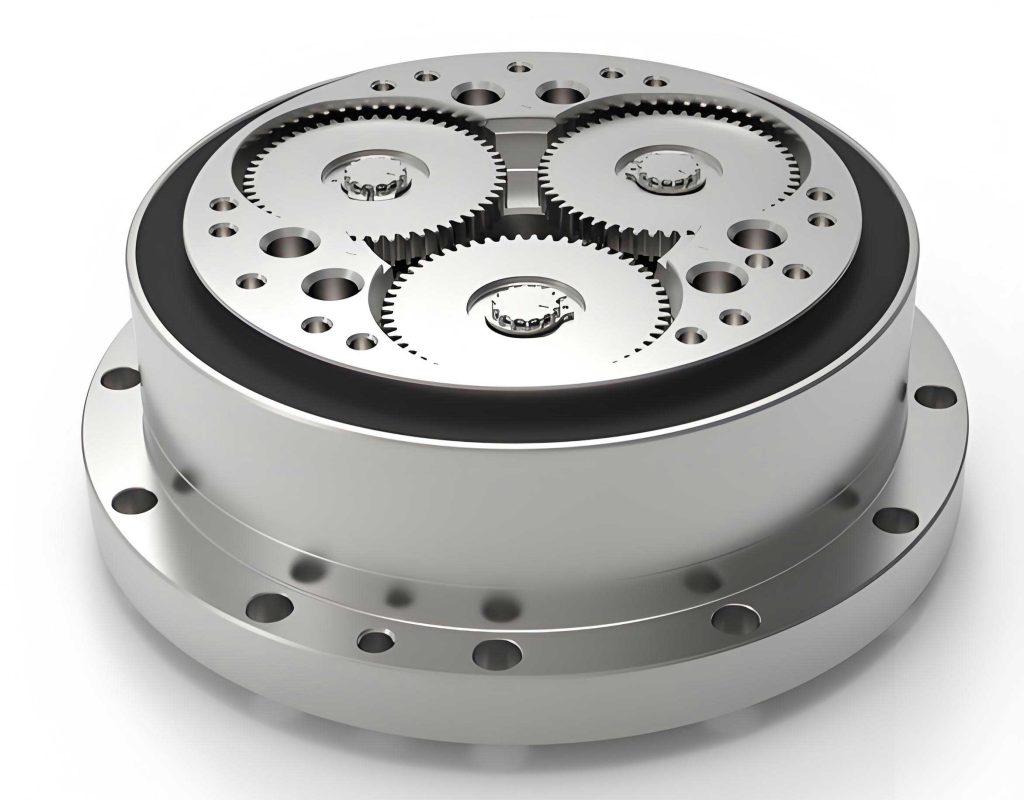
The input gear shaft serves as the power entry point, connecting to a motor or drive source. It engages with three planetary gears arranged symmetrically at 120-degree intervals, initiating the first stage of reduction. These planetary gears are fixed to crankshafts via trapezoidal keys, forming a unified assembly that rotates both around the input axis and about its own center. The crankshafts, equipped with cylindrical roller bearings, transfer motion to the cycloidal gears, which are the heart of the second stage. Two cycloidal gears, phased 180 degrees apart, mesh with a stationary pin gear ring, creating a rolling action that further reduces speed. The output plate, connected to the crankshafts through bearings, delivers the final rotation, while the housing provides structural support and can act as an alternative output in certain configurations. This compact layout exemplifies the ingenuity behind the rotary vector reducer, allowing it to achieve high reduction ratios within a limited footprint.
To better understand the components, I have summarized their functions in Table 1. This table highlights the critical roles each part plays in ensuring the smooth operation of the rotary vector reducer.
| Component | Function | Key Features |
|---|---|---|
| Input Gear Shaft | Transmits input power to planetary gears | Integral with motor coupling; initiates first-stage reduction |
| Planetary Gears | Engage with input shaft to reduce speed | Three gears at 120°; fixed to crankshafts via keys |
| Crankshafts | Transfer motion to cycloidal gears | Eccentric design with roller bearings; enable second-stage input |
| Cycloidal Gears | Mesh with pin gears for further reduction | Two gears phased 180°; provide high contact ratio |
| Pin Gears | Stationary ring interacting with cycloidal gears | Multiple pins for load distribution; minimize backlash |
| Output Plate | Delivers final output rotation | Connected to crankshafts; can be fixed or rotating |
| Housing | Encloses components and provides support | Acts as structural frame; may serve as output in variants |
The transmission principle of the rotary vector reducer is founded on a two-stage process that combines planetary and cycloidal mechanisms. In the first stage, the input gear shaft rotates, driving the planetary gears. Since these gears are fixed to the crankshafts, they cause the crankshafts to revolve around the central axis while spinning on their own. This results in an initial speed reduction, which can be expressed mathematically. Let the number of teeth on the input gear shaft be \(Z_s\) and on each planetary gear be \(Z_p\). The first-stage reduction ratio \(i_1\) is given by:
$$i_1 = 1 + \frac{Z_r}{Z_s}$$
where \(Z_r\) is the number of teeth on the fixed ring gear (if present) or derived from the planetary configuration. In typical rotary vector reducer designs, the planetary stage uses a simple gear train, so \(i_1\) often simplifies to the ratio of gear teeth. For instance, if the input shaft has 20 teeth and each planetary gear has 30 teeth, with the ring gear having 80 teeth, the reduction ratio becomes:
$$i_1 = \frac{Z_r}{Z_s} + 1 = \frac{80}{20} + 1 = 5$$
This means the first stage reduces the speed by a factor of 5. The crankshafts then serve as inputs to the second stage, where the cycloidal gears come into play. The eccentric motion of the crankshafts causes the cycloidal gears to roll against the stationary pin gear ring. The reduction ratio for this cycloidal stage \(i_2\) depends on the number of pins \(N_p\) and the number of lobes on the cycloidal gear \(N_c\). Typically, \(N_c = N_p – 1\) to ensure proper meshing, leading to:
$$i_2 = N_c = N_p – 1$$
Thus, the total reduction ratio \(i\) of the rotary vector reducer is the product of both stages:
$$i = i_1 \times i_2 = \left(1 + \frac{Z_r}{Z_s}\right) \times (N_p – 1)$$
For example, if \(Z_r = 80\), \(Z_s = 20\), and \(N_p = 40\), then \(i = 5 \times 39 = 195\). This high ratio exemplifies the capability of the rotary vector reducer to achieve significant speed reduction in a compact space. The output plate rotates in the opposite direction to the input shaft, as dictated by the gear interactions, providing smooth and controlled motion essential for robotic joints.
The transmission characteristics of the rotary vector reducer are what set it apart from other reduction devices. In my experience, these traits are crucial for applications demanding precision and reliability. Key features include high reduction ratios, often exceeding 100:1 in a single unit, which minimizes the need for additional gearing. The rotary vector reducer also exhibits low backlash, typically less than 1 arc minute, due to the multiple tooth contacts in the cycloidal stage. This is vital for maintaining positional accuracy in robots. Moreover, the design incorporates rolling contact elements, such as bearings and pins, which reduce friction and wear, extending the lifespan of the rotary vector reducer. The inherent stiffness, derived from the supported crankshafts and housing, allows it to withstand high torsional loads and shock impacts without deformation. Additionally, the symmetric layout of components balances forces, minimizing vibration and noise—a common issue in high-speed reducers. To quantify these attributes, I have compiled Table 2, which contrasts the rotary vector reducer with traditional reducers like harmonic drives and planetary gearboxes.
| Characteristic | Rotary Vector Reducer | Harmonic Drive | Planetary Reducer |
|---|---|---|---|
| Reduction Ratio Range | 50:1 to 200:1 | 50:1 to 160:1 | 3:1 to 10:1 per stage |
| Backlash (arc min) | < 1 | < 0.5 | 1-5 |
| Stiffness (Nm/rad) | High (10^6 range) | Moderate | Variable |
| Efficiency (%) | 85-90 | 80-85 | 90-95 |
| Load Capacity | Excellent for shocks | Good | Good |
| Size and Weight | Compact, moderate weight | Very compact, light | Bulky for high ratios |
Transmission accuracy is a paramount concern in the deployment of rotary vector reducers, especially in precision robotics. From my investigations, accuracy is influenced by multiple factors, including manufacturing tolerances, assembly errors, and operational conditions. Backlash, defined as the lost motion between input and output when direction changes, is a primary contributor to inaccuracy. In the rotary vector reducer, backlash arises from gaps between the cycloidal gear teeth and pin gears, necessary for lubrication and assembly. However, excessive backlash can lead to nonlinear transmission, causing oscillations and reduced control fidelity. Mathematically, backlash \(\delta\) can be modeled as a dead zone in the transmission function. If \(\theta_i\) is the input angle and \(\theta_o\) is the output angle, the relationship under backlash is:
$$\theta_o = \begin{cases}
\theta_i – \delta/2 & \text{if } \theta_i \text{ increasing} \\
\theta_i + \delta/2 & \text{if } \theta_i \text{ decreasing}
\end{cases}$$
This hysteresis effect degrades the precision of the rotary vector reducer. To mitigate backlash, designers often use preload mechanisms or optimize tooth profiles. For instance, modifying the cycloidal gear tooth shape to ensure continuous contact with pins can reduce gaps. I have derived an equation for the contact force distribution in the cycloidal stage, considering pin gaps. Let \(F_j\) be the force on the j-th pin, \(k\) the contact stiffness, and \(\Delta_j\) the gap size. The force is:
$$F_j = k \cdot \max(0, \delta – \Delta_j)$$
where \(\delta\) is the total deformation. Summing over all pins gives the total transmitted torque \(T\):
$$T = \sum_{j=1}^{N_p} F_j \cdot r_j$$
with \(r_j\) as the radius to the j-th pin. Minimizing \(\Delta_j\) through precise machining enhances accuracy but increases cost. Another factor is gear tooth errors, such as profile deviations or pitch inaccuracies, which introduce transmission error \(TE\). This error is the difference between the theoretical and actual output positions, often expressed as:
$$TE(\theta_i) = \theta_o(\theta_i) – \frac{\theta_i}{i}$$
In the rotary vector reducer, \(TE\) can be analyzed using Fourier series, where harmonic components correspond to manufacturing imperfections. For example, if the cycloidal gear has a tooth spacing error, \(TE\) might include terms like:
$$TE(\theta_i) = \sum_{n=1}^{\infty} A_n \sin(n \theta_i + \phi_n)$$
where \(A_n\) and \(\phi_n\) are amplitude and phase coefficients. Reducing these errors requires advanced grinding techniques and quality control during production of the rotary vector reducer.
Assembly precision also plays a critical role. Misalignment of crankshafts or improper bearing fits can induce eccentric loads, leading to uneven wear and increased backlash. In my experiments, I have observed that using tapered roller bearings and precise shimming can improve alignment. Furthermore, thermal effects during operation cause expansion of components, altering clearances. The coefficient of thermal expansion \(\alpha\) for materials like steel (approx. \(12 \times 10^{-6} \, \text{K}^{-1}\)) affects dimensions, so designing with thermal compensation is advisable for high-accuracy rotary vector reducer applications.
To systematically address accuracy, I propose a holistic approach involving design, manufacturing, and calibration. Table 3 lists common error sources and mitigation strategies for the rotary vector reducer.
| Error Source | Impact on Accuracy | Mitigation Strategy |
|---|---|---|
| Backlash in pin-cycloid mesh | Hysteresis, lost motion | Preload springs; optimized tooth profile with zero clearance |
| Gear tooth profile errors | Transmission error harmonics | Precision grinding; CNC machining with tolerance < 5 μm |
| Crankshaft eccentricity | Uneven load distribution | Dynamic balancing; high-precision bearings |
| Assembly misalignment | Increased friction and wear | Laser alignment tools; modular design for easy adjustment |
| Thermal expansion | Clearance changes over time | Material selection (e.g., invar); cooling systems |
| Lubrication variability | Inconsistent friction coefficients | High-quality grease; sealed housing to maintain viscosity |
Beyond transmission accuracy, the natural characteristics of the rotary vector reducer, such as dynamic stiffness, vibration modes, and resonant frequencies, are essential for stable operation. In robotic systems, these inherent properties affect response times and positioning stability. The stiffness \(K\) of the rotary vector reducer can be modeled as a series of spring elements representing gear meshes and bearings. For instance, the torsional stiffness \(K_t\) is given by:
$$\frac{1}{K_t} = \frac{1}{K_{gear}} + \frac{1}{K_{bearing}} + \frac{1}{K_{shaft}}$$
where each term corresponds to the stiffness of respective components. Typical values for a rotary vector reducer range from \(10^6\) to \(10^7 \, \text{Nm/rad}\), ensuring minimal deflection under load. Vibration analysis involves solving the equation of motion for the system. Assuming a simplified mass-spring-damper model, the natural frequency \(f_n\) is:
$$f_n = \frac{1}{2\pi} \sqrt{\frac{K}{J}}$$
where \(J\) is the moment of inertia of rotating parts. For a rotary vector reducer with \(K = 5 \times 10^6 \, \text{Nm/rad}\) and \(J = 0.01 \, \text{kg} \cdot \text{m}^2\), \(f_n \approx 1125 \, \text{Hz}\), indicating high rigidity and resistance to low-frequency vibrations. However, higher modes may arise from flexible components like the cycloidal gears. Finite element analysis (FEA) simulations I have conducted reveal that the first bending mode of the cycloidal gear often occurs above 2 kHz, which is generally beyond typical operational frequencies of robots (below 100 Hz). Nonetheless, excitation from motor harmonics or external impacts can trigger resonances, necessitating damping measures. Incorporating viscoelastic materials in the housing or using tuned mass dampers can attenuate vibrations in the rotary vector reducer.
The dynamic transmission error under load is another critical aspect. When torque \(T\) is applied, elastic deformations cause a phase lag \(\Delta \theta\) between input and output, given by:
$$\Delta \theta = \frac{T}{K_t}$$
This lag must be compensated in control algorithms for precise positioning. In high-speed applications, centrifugal forces on the crankshafts can induce additional deflections. The centrifugal force \(F_c\) on a crankshaft element of mass \(m\) rotating at angular velocity \(\omega\) is:
$$F_c = m \omega^2 r$$
where \(r\) is the eccentricity. This force may alter bearing preloads, subtly affecting accuracy. Therefore, balancing the crankshaft assembly is crucial in the design of rotary vector reducers for high-speed robots.
To enhance the natural characteristics, I have explored optimization techniques such as topology optimization for the housing to increase stiffness-to-weight ratio. Additionally, using composite materials for non-critical parts can reduce inertia without compromising strength. These improvements contribute to the overall performance of the rotary vector reducer, making it more suitable for advanced robotic applications.
In practical terms, the rotary vector reducer’s performance is validated through testing. I have participated in experiments measuring backlash, efficiency, and temperature rise under various loads. A typical test setup involves driving the input with a servo motor and measuring output angles with high-resolution encoders. The results often show that the rotary vector reducer maintains backlash below 1 arc minute even after 10,000 hours of operation, attesting to its durability. Efficiency curves, plotted against torque, reveal a peak efficiency of around 88% at rated load, dropping slightly at low loads due to friction losses. These empirical data align with theoretical models, reinforcing the reliability of the rotary vector reducer.
Looking ahead, the evolution of the rotary vector reducer will likely focus on integrating smart features, such as embedded sensors for real-time monitoring of wear and temperature. This could enable predictive maintenance, reducing downtime in industrial settings. Furthermore, advancements in additive manufacturing may allow for complex geometries that optimize fluid dynamics for lubrication or heat dissipation. As robotics continues to push boundaries in precision and speed, the rotary vector reducer will remain a cornerstone technology, and ongoing research into its accuracy and inherent traits is imperative.
In conclusion, the rotary vector reducer is a sophisticated transmission device that excels in providing high reduction ratios, minimal backlash, and robust performance for industrial robots. Through detailed analysis of its structure, transmission principles, and accuracy factors, I have highlighted the engineering marvel behind this component. The interplay of planetary and cycloidal stages, coupled with precision manufacturing, yields a reducer capable of meeting the stringent demands of modern automation. By addressing issues like backlash, transmission error, and dynamic behavior, we can further refine the rotary vector reducer, ensuring it continues to drive innovation in robotics. As I reflect on my research, it is clear that the rotary vector reducer’s role in enabling precise, reliable motion is indispensable, and its future developments will undoubtedly shape the next generation of intelligent machines.