
In modern industrial applications, the demand for compact, high-precision, and high-load-capacity transmission systems has driven significant advancements in减速器 technology. Among these, the cycloidal drive, particularly the 2K-V type, stands out due to its exceptional performance characteristics. As a researcher in mechanical engineering, I have extensively studied the evolution, principles, and structural intricacies of the 2K-V cycloidal drive. This article aims to provide a comprehensive overview, focusing on its development, operational mechanisms, kinematic analyses, and design features. The cycloidal drive, with its unique configuration, offers advantages such as a wide transmission ratio range, high motion accuracy, efficiency, minimal backlash, and robust load-bearing capacity, making it indispensable in fields like robotics, CNC machine tools, and automation equipment.
The journey of the cycloidal drive began in 1926 when a German inventor pioneered the initial design, laying the groundwork for future innovations. However, it was the Japanese companies that propelled its commercialization. In the late 1930s, Sumitomo Heavy Industries introduced and refined the technology, leading to the launch of the 50-series cycloidal drives in the 1960s. These early models demonstrated the potential of cycloidal drives in various industries. By the 1980s, Teijin Seiki Co., Ltd. developed the 2K-V cycloidal drive, integrating a two-stage transmission system that enhanced performance. Over the decades, continuous improvements have resulted in series like RV-E, RV-C, and the more compact RV-N, while Chinese manufacturers have also accelerated their research and production efforts. To summarize key milestones, the following table outlines the historical progression of cycloidal drive technology:
| Year | Event | Significance |
|---|---|---|
| 1926 | Invention in Germany | Foundation of cycloidal drive principles |
| 1930s | Introduction to Japan by Sumitomo | Initial adaptation and refinement |
| 1960s | Launch of 50-series cycloidal drives | Commercialization with improved reliability |
| 1986 | Teijin’s 2K-V cycloidal drive market entry | Integration of two-stage transmission for enhanced performance |
| 1990s-present | Development of RV series and global expansion | Ongoing innovation in compactness and load capacity |
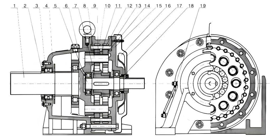
The working principle of the 2K-V cycloidal drive revolves around a two-stage减速 mechanism that combines a planetary gear system with a cycloidal pinwheel transmission. In the first stage, an input sun gear, connected to a motor, engages with evenly distributed planetary gears to achieve initial speed reduction. The second stage involves a double or triple crank mechanism that drives a cycloidal disk, which meshes with a fixed or rotating pinwheel to produce further减速. Specifically, when the pinwheel is fixed, the crank shafts, integrated with the planetary gears, undergo both rotation and revolution, leading to output through a carrier. This configuration ensures smooth power transmission and high torque output. To visualize this mechanism, consider the following diagram that illustrates the internal components and flow of motion in a cycloidal drive system.
From a kinematic perspective, analyzing the degrees of freedom is crucial for understanding the motion constraints of the cycloidal drive. For the 2K-V type, the system comprises key moving parts: a sun gear, planetary cranks (which integrate planetary gears and crank shafts), a cycloidal disk, and either a pinwheel or carrier, depending on the configuration. When the carrier is fixed, the moving components include the sun gear, two planetary cranks, and the pinwheel, resulting in five moving links (n = 5). The joints consist of six revolute pairs (e.g., between gears and frames) and two higher pairs (gear meshes), giving $F_l = 6$ and $F_h = 2$. Using the Grübler’s formula for planar mechanisms, the degrees of freedom $F$ can be calculated as:
$$F = 3n – 2F_l – F_h$$
Substituting the values:
$$F = 3 \times 5 – 2 \times 6 – 2 = 15 – 12 – 2 = 1$$
This result indicates a single degree of freedom, meaning the cycloidal drive operates with a determinate motion, essential for precise control in applications like robotics. Similarly, when the pinwheel is fixed, the moving parts change to the sun gear, planetary cranks, carrier, and cycloidal disk, but the count remains n = 5, with $F_l = 6$ and $F_h = 2$, yielding the same $F = 1$. This consistency underscores the stability of the cycloidal drive design across different operational modes.
Transmission ratio calculation is another vital aspect, as it determines the speed reduction capability of the cycloidal drive. The 2K-V cycloidal drive employs a compound gear system, and the overall ratio can be derived using the method of relative motion or transformation. For instance, when the pinwheel is fixed, the input is from the sun gear, and the output is from the carrier. By applying a reversed angular velocity equal to that of the carrier, the system converts into a fixed-axis gear train, allowing for straightforward ratio analysis. Let $n_1$ be the sun gear speed, $n_2$ the planetary gear speed, $n_3$ the cycloidal disk speed, $n_4$ the pinwheel speed (fixed at zero), and $n_w$ the carrier speed. The first-stage ratio for the planetary gear set is given by:
$$i_{w12} = \frac{n_1 – n_w}{n_2 – n_w} = -\frac{z_2}{z_1}$$
where $z_1$ and $z_2$ are the tooth numbers of the sun gear and planetary gear, respectively. For the second-stage cycloidal transmission, considering the relative motion, the ratio involves the cycloidal disk and pinwheel. With $z_3$ as the cycloidal disk teeth and $z_4$ as the pinwheel teeth (where $z_4 = z_3 + 1$ due to the hypocycloidal geometry), the relationship is:
$$i_{w’34} = \frac{n_3^w – n_w’}{n_4^w – n_w’} = \frac{z_4}{z_3}$$
Here, $n_3^w = n_3 – n_w$, $n_4^w = n_4 – n_w = -n_w$ (since $n_4 = 0$), and $n_w’ = n_2 – n_w$. Solving these equations, the overall transmission ratio $i_{1w}$ of the cycloidal drive becomes:
$$i_{1w} = \frac{n_1}{n_w} = 1 + \frac{z_2 z_4}{z_1}$$
This formula highlights the large reduction ratios achievable by the cycloidal drive, often reaching hundreds, thanks to the multiplicative effect of the two stages. For example, with typical values like $z_1 = 20$, $z_2 = 30$, and $z_4 = 40$, the ratio calculates to $i_{1w} = 1 + (30 \times 40) / 20 = 61$, demonstrating the compact yet powerful nature of the cycloidal drive. To further illustrate, the table below compares transmission ratios for different cycloidal drive configurations:
| Component Teeth Numbers | Transmission Ratio ($i_{1w}$) | Application Example |
|---|---|---|
| $z_1=15, z_2=45, z_4=50$ | $1 + (45 \times 50) / 15 = 151$ | Heavy-duty robotics |
| $z_1=25, z_2=35, z_4=40$ | $1 + (35 \times 40) / 25 = 57$ | CNC machine tools |
| $z_1=30, z_2=30, z_4=31$ | $1 + (30 \times 31) / 30 = 32$ | Precision automation |
Structurally, the 2K-V cycloidal drive consists of six key components that integrate seamlessly to deliver high performance. These include the pinwheel housing, planetary gears, crank shaft assemblies, input gear shaft, cycloidal disk, and the output carrier with support flange. The design incorporates several innovative features: a built-in main bearing system to support external loads and enhance rigidity; a dual-column support mechanism from the carrier and flange to increase torsional stiffness and shock resistance; crank shafts equipped with rolling bearings to reduce wear and extend lifespan; and a pin-gear mechanism formed by the cycloidal disk and pinwheel to minimize backlash. Notably, the use of multiple crank shafts, as opposed to a single crank in traditional cycloidal drives, enables power splitting, which distributes loads evenly and improves durability. The following table summarizes the structural components and their functions in the cycloidal drive:
| Component | Function | Impact on Performance |
|---|---|---|
| Pinwheel Housing | Holds pinwheel pins and provides mounting | Ensures alignment and reduces vibration |
| Planetary Gears | First-stage speed reduction | Enables initial torque multiplication |
| Crank Shaft Assemblies | Transmit motion to cycloidal disk | Facilitates power splitting for higher load capacity |
| Input Gear Shaft | Connects to motor for power input | Direct drive integration for efficiency |
| Cycloidal Disk | Meshes with pinwheel for second-stage reduction | Key to high precision and low backlash |
| Output Carrier | Provides output rotation | Enhances rigidity and moment resistance |
The performance characteristics of the cycloidal drive are what make it superior in many industrial scenarios. Firstly, its transmission ratio range is extensive, often exceeding 100:1, due to the combined effects of the planetary and cycloidal stages. Secondly, the load-bearing capacity is remarkable, with some models supporting moments up to 900 N·m, thanks to the robust frame-like output structure. Thirdly, stiffness is high, with torsional rigidity values reaching 3,727 N·m/arcmin, which minimizes deflection under load. Fourthly, efficiency typically ranges from 85% to 92%, reducing energy losses. Fifthly, motion accuracy is exceptional, with smooth operation and low noise production. Lastly, backlash is minimal, often below one arcminute, crucial for precision applications. However, achieving these benefits requires meticulous manufacturing, especially for the cycloidal disk, as even minor errors can lead to lubrication issues, increased wear, and reduced accuracy. To quantify these attributes, consider the following performance metrics for a standard cycloidal drive:
| Performance Metric | Typical Value | Importance in Applications |
|---|---|---|
| Transmission Ratio Range | 30:1 to 200:1 | Allows flexible speed control in diverse machinery |
| Load Capacity (Moment) | Up to 900 N·m | Supports heavy-duty operations in robotics and automation |
| Torsional Rigidity | 3,727 N·m/arcmin | Ensures precision under variable loads |
| Efficiency | 85-92% | Reduces power consumption and heat generation |
| Backlash | < 1 arcmin | Critical for high-accuracy positioning systems |
| Operating Noise | Low (below 60 dB) | Enhances user comfort in industrial environments |
In terms of design optimization, the cycloidal drive continues to evolve. Recent advancements focus on material science, such as using hardened steels or composites for the cycloidal disk to enhance wear resistance, and on lubrication systems to ensure long-term reliability. Computational tools like finite element analysis (FEA) are employed to simulate stress distributions and predict fatigue life. For instance, the contact stresses between the cycloidal disk and pinwheel pins can be modeled using Hertzian contact theory, with the maximum stress $\sigma_{max}$ given by:
$$\sigma_{max} = \sqrt{\frac{F E^*}{\pi R}}$$
where $F$ is the normal load, $E^*$ is the equivalent Young’s modulus, and $R$ is the effective radius of curvature. This helps in designing cycloidal drives that withstand millions of cycles without failure. Additionally, the trend toward miniaturization has led to compact cycloidal drive versions like the RV-N series, which maintain high performance in smaller footprints, ideal for space-constrained applications like collaborative robots.
Looking ahead, the future of cycloidal drive technology appears promising, with ongoing research into smart monitoring systems that use sensors to detect wear and optimize maintenance schedules. The integration of cycloidal drives with direct-drive motors and IoT connectivity could revolutionize industrial automation. Moreover, as global industries emphasize sustainability, the efficiency and durability of cycloidal drives contribute to energy savings and reduced environmental impact. In my analysis, the cycloidal drive represents a pinnacle of mechanical design, blending historical innovation with modern engineering to meet the ever-growing demands of precision motion control.
In conclusion, the 2K-V cycloidal drive is a sophisticated transmission solution that excels in various demanding applications. From its historical roots to its advanced structural features, the cycloidal drive offers a unique combination of high reduction ratios, precision, and robustness. Through detailed kinematic and dynamic analyses, including freedom degree calculations and transmission ratio derivations, we can appreciate its engineering elegance. As technology progresses, further refinements in materials, manufacturing, and integration will likely expand the capabilities of cycloidal drives, solidifying their role as a cornerstone in modern machinery. This deep dive into the cycloidal drive underscores its importance and inspires continued innovation in the field of power transmission systems.