
The pursuit of higher power density, precision, and reliability in precision transmission systems, particularly for robotic joints, has cemented the position of the Rotary Vector (RV) reducer as a critical component. This sophisticated two-stage, closed differential planetary drive, evolved from the traditional cycloidal drive, offers superior advantages in compactness, high reduction ratio, longevity, and torsional stiffness. A cornerstone of its design lies in the intricate process of tooth matching for its composite gear trains. This article delves into a systematic methodology for tooth matching and subsequently establishes a parametric framework to minimize the overall volume of the rotary vector reducer, thereby enhancing its power-to-weight and power-to-volume ratios.
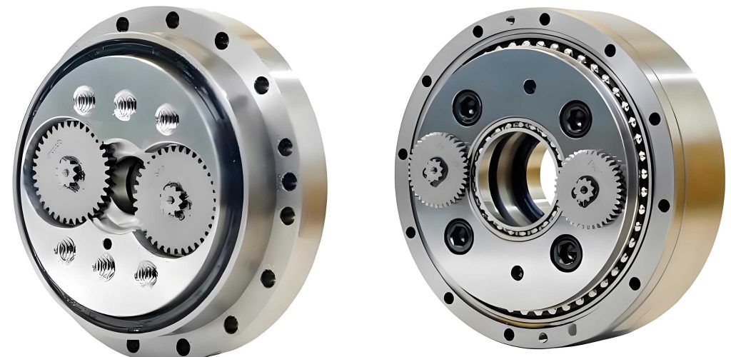
The typical structure of an rotary vector reducer integrates a first-stage involute planetary gear train with a second-stage cycloidal-pin gear planetary train. Primary components include the sun gear (center gear), planetary gears, crankshafts, cycloidal disks, a pin housing (ring), and the output carrier. Power flows from the input sun gear to the planetary gears, which drive the crankshafts. The eccentric motion of the crankshafts then drives the cycloidal disks, which mesh with the stationary pin teeth in the housing, forcing the carrier to rotate at a greatly reduced speed. This unique configuration is what grants the rotary vector reducer its exceptional characteristics.
Systematic Tooth Matching for the RV Reducer
The kinematic design, or “tooth matching,” of the rotary vector reducer must satisfy a set of interrelated geometric, kinematic, and assembly constraints. The overall reduction ratio, with the housing fixed, is derived from the kinematics of the compound planetary system:
$$ i = 1 + \frac{Z_5}{Z_1} \cdot \frac{Z_2}{Z_2 – Z_1} $$
Where \( Z_1 \) is the number of teeth on the sun gear (first stage), \( Z_2 \) is the number of teeth on each planetary gear, and \( Z_5 \) is the number of pin teeth on the housing (second stage). This equation is fundamental to all subsequent calculations for the rotary vector reducer.
Beyond the ratio, several critical conditions must be met simultaneously:
- Assembly Condition for Multiple Planets: In a three-planet rotary vector reducer, traditional theory demands that the sun gear teeth \( Z_1 \) be a multiple of the number of planets (3) for even spacing. However, this severely limits design flexibility. Modern practice employs calculated rotation angles during gear machining to allow for non-multiples, ensuring proper phasing of the three crankshafts and correct meshing of the two opposed cycloidal disks.
- Non-undercutting Condition: To prevent gear undercutting in the involute stage, the sun gear must have a sufficient number of teeth: \( Z_1 \geq 17 \).
- Load Distribution Condition: To prevent excessive torque on the more sensitive cycloidal stage, the gear ratio of the first planetary stage should be constrained: \( 3.0 \leq \frac{Z_2}{Z_1} \leq 4.5 \).
- Single-Tooth-Difference Condition: The core principle of the second-stage cycloidal drive requires a tooth difference of one. Therefore, the pin tooth count must be even: \( Z_5 \) is an even integer, and the cycloid disk tooth count is \( Z_4 = Z_5 – 1 \).
- Structural Dimension Condition: A crucial empirical relationship links the two stages. The center distance \( a_0 \) of the first-stage gears must be proportional to the pin circle radius \( R_z \) of the second stage to ensure balanced force distribution on the crankshafts: \( a_0 = (0.5 \sim 0.6)R_z \), where \( a_0 = \frac{m(Z_1 + Z_2)}{2} \) for a standard module \( m \).
The pin circle radius \( R_z \) is itself a function of the output torque \( T \), derived from empirical design formulas considering system efficiency:
$$ R_z = K_t \sqrt[3]{T} $$
$$ T = 9549 \cdot \frac{P}{n} \cdot i \cdot \eta $$
$$ \eta = \eta_{1-6} \cdot \eta_{B} = \eta_{1-6} \cdot \eta_{B1} \cdot \eta_{B2} \cdot \eta_{B3} $$
$$ \eta_{1-6} = 1 – (1 – \eta_{12}^H)(1 – \eta_{54}^H) $$
Here, \( K_t \) is a design coefficient, \( P \) is input power, \( n \) is input speed, \( \eta_{12}^H \) is the involute gear mesh efficiency (~0.992), \( \eta_{54}^H \) is the cycloidal mesh efficiency (~0.998), and \( \eta_{B1}, \eta_{B2}, \eta_{B3} \) are bearing efficiencies (~0.99 each).
Manually finding integer combinations of \( Z_1, Z_2, Z_5 \) that satisfy all these constraints for a given ratio and torque is tedious. A systematic approach involves implementing the logic flow into a computational algorithm. The process can be summarized as follows:
- Define target ratio \( i \), torque \( T \), module \( m \), and other fixed parameters.
- Iterate over a reasonable range for \( Z_1 \) (from 17 upward).
- For each \( Z_1 \), solve the ratio equation for \( Z_2 \) as a function of \( Z_5 \): \( Z_2 = \frac{Z_1 (i – 1)}{Z_5 + Z_1 (i – 1)} \cdot Z_5 \). Since \( Z_2 \) must be an integer, iterate over even \( Z_5 \) values to find integer \( Z_2 \).
- Filter results using the load distribution condition \( 3.0 \leq Z_2/Z_1 \leq 4.5 \).
- Calculate \( a_0 \) and the required \( R_z \) from torque. Check if \( a_0 \approx (0.5-0.6)R_z \).
- Output all valid integer triplets \( (Z_1, Z_2, Z_5) \).
Implementing this algorithm, for example in Visual Basic.NET, yields a series of viable configurations. For a module \( m = 1.25 \) mm, a subset of possible tooth combinations is presented below:
| Sun Gear Teeth (Z₁) | Planet Gear Teeth (Z₂) | Pin Teeth (Z₅) | Theoretical Ratio (i) |
|---|---|---|---|
| 18 | 63 | 40 | 141.00 |
| 19 | 68 | 38 | 113.95 |
| 20 | 72 | 40 | 109.00 |
| 21 | 75 | 42 | 111.00 |
| 22 | 75 | 32 | 90.09 |
| 23 | 81 | 46 | 115.87 |
| 24 | 84 | 44 | 110.00 |
Determining Gear Widths Based on Strength Criteria
After establishing the tooth numbers, the next critical step in sizing the rotary vector reducer is determining the necessary face widths for the gears to ensure reliable operation under load.
Bending and Contact Fatigue for Involute Gears
The first-stage involute gears are primarily subject to bending fatigue at the tooth root and contact fatigue (pitting) on the tooth flank. The minimum face width \( b \) is governed by the more demanding of these two criteria.
Bending Fatigue Strength: The condition to avoid tooth breakage is \( \sigma_F \leq [\sigma_F] \). The design formula derived from the Lewis equation with corrections yields the required width:
$$ b \geq \frac{2 K_F T_1 Y_{Fa} Y_{Sa}}{m d_1 [\sigma_F]} $$
Where \( K_F \) is the load factor (~1.2), \( T_1 \) is the torque on the pinion (sun gear), \( Y_{Fa} \) and \( Y_{Sa} \) are the tooth form factor and stress correction factor (e.g., 2.65 and 1.64 for standard teeth), \( m \) is the module, \( d_1 = m Z_1 \) is the pitch diameter of the sun gear, and \( [\sigma_F] \) is the allowable bending stress (e.g., 520 MPa for hardened steel).
Contact Fatigue Strength: The condition to prevent surface pitting is \( \sigma_H \leq [\sigma_H] \). The derived design formula from the Hertzian contact stress equation is:
$$ b \geq \left( \frac{Z_H Z_E}{[\sigma_H]} \right)^2 \cdot \frac{2 K_H T_1}{d_1^2} \cdot \frac{u + 1}{u} $$
Where \( K_H \) is the contact load factor (~1.3), \( Z_H \) is the zone factor (~2.35), \( Z_E \) is the elasticity factor (~189.8 MPa¹ᐟ²), \( [\sigma_H] \) is the allowable contact stress (e.g., 680 MPa), and \( u = Z_2 / Z_1 \).
The larger of the two widths calculated from the above equations is selected for the involute gear pair.
Contact Strength for the Cycloid-Pin Mesh
The second-stage cycloid drive is highly robust against bending but is susceptible to contact stress issues between the cycloid disk and the pins, which can lead to pitting or spalling. The Hertzian contact stress at the most heavily loaded point can be approximated by:
$$ \sigma_{H_{max}} = 0.418 \sqrt{\frac{F_{max} E_e}{B \rho_{emin}}} \leq \sigma_{HP} $$
Where:
- \( F_{max} \) is the maximum force on a pin, related to the output torque \( T \), pin circle radius \( R_z \), and number of crankshafts \( N \) (typically 3): \( F_{max} \approx \frac{2T}{N R_z} \).
- \( E_e \) is the equivalent elastic modulus (~2.06×10⁵ MPa for steel-steel contact).
- \( \rho_{emin} \) is the minimum equivalent radius of curvature at the contact point, which for a cycloid profile and round pins is a function of the pin radius \( r_p \), eccentricity \( e \), and tooth numbers. A simplified relation is \( \rho_{emin} \approx \frac{r_p (R_z – r_p)}{e Z_5} \).
- \( \sigma_{HP} \) is the allowable contact stress for the material pair (e.g., 1100 MPa for GCr15 cycloid disk vs. 20CrMnMo pin).
From this constraint, the minimum required width \( B \) for the cycloid disk can be derived:
$$ B \geq \frac{0.1747 \cdot F_{max} \cdot E_e}{\rho_{emin} \cdot (\sigma_{HP})^2} $$
Empirically, the cycloid disk width is also related to the pin circle radius, typically \( B = (0.1 \sim 0.2) R_z \). The final chosen \( B \) must satisfy both the calculated strength requirement and this empirical range.
Volumetric Model and Optimization Objective
The primary goal of this structural optimization for the rotary vector reducer is to minimize its overall envelope volume, which directly correlates with material usage, weight, and cost. A simplified yet effective volumetric model focuses on the three main gear components: the involute planetary gearset and the cycloid-pin set. The total volume \( V \) can be approximated as:
$$ V = V_1 + V_2 + V_3 $$
- Involute Gear Volume (V₁): Approximated as the total volume of the sun gear and one planet gear (multiplied by number of planets later in optimization loops).
$$ V_1 \approx \frac{\pi}{4} b \left[ (m Z_1)^2 + N_p \cdot (m Z_2)^2 \right] $$
where \( N_p \) is the number of planets (3). - Cycloid Disk Volume (V₂): Modeled as a hollow cylinder with outer radius approximately equal to the pin circle radius \( R_z \) and inner radius related to the crank bearing.
$$ V_2 \approx N_c \cdot \pi B \left( R_z^2 – (R_z – 2e – r_{brg})^2 \right) $$
where \( N_c \) is the number of cycloid disks (2), \( e \) is the eccentricity, and \( r_{brg} \) is the radius to the crank bearing bore. - Pin Gear Volume (V₃): Approximated as the volume of the ring housing containing the pins.
$$ V_3 \approx \pi B_{housing} \left( (R_z + r_p + \delta)^2 – (R_z – r_p – \delta)^2 \right) $$
where \( B_{housing} \) is the housing width (slightly larger than \( B \)), \( r_p \) is the pin radius, and \( \delta \) is a wall thickness allowance.
The eccentricity \( e \) is a key design parameter: \( e = \frac{a_0}{Z_2 / Z_1} \) is not correct for the cycloid stage. For a standard cycloid, the eccentricity is related to the pin circle radius and tooth difference: \( e = \frac{R_z}{Z_5} \). Also, \( a_0 = m (Z_1 + Z_2)/2 \). The structural condition \( a_0 = (0.5-0.6)R_z \) links these parameters.
Thus, the optimization problem is formally defined as:
Minimize: \( V(Z_1, Z_2, Z_5, m, b, B, …) \)
Subject to:
- Kinematic and Assembly Constraints (Ratio equation, assembly condition, single-tooth-difference).
- Geometric Constraints (Non-undercutting, load distribution range, structural dimension condition).
- Strength Constraints (Bending \( \sigma_F \leq [\sigma_F] \), Contact \( \sigma_H \leq [\sigma_H] \), Cycloid contact \( \sigma_{H_{max}} \leq \sigma_{HP} \)).
- Empirical/Boundary Constraints ( \( b, B > 0 \), \( B \approx (0.1-0.2)R_z \), module from standard series).
Optimization Process and Design Example
The optimization integrates the systematic tooth-matching algorithm with the strength and volume calculations. The process is parameterized and can be implemented in a computational environment like Visual Basic.NET or MATLAB:
- Define fixed inputs: Power \( P \), Input Speed \( n \), Target Ratio \( i_{target} \), Material Properties, Safety Factors.
- Execute the tooth-matching algorithm to generate the set \( S \) of all valid \( (Z_1, Z_2, Z_5) \) triplets.
- For each valid triplet in \( S \):
- Calculate initial geometry: \( a_0 \), \( R_z \) (from torque and the condition \( a_0 = \lambda R_z \), where \( \lambda \) is varied between 0.5 and 0.6).
- Determine minimum required widths \( b \) and \( B \) from all strength constraints.
- Calculate the total volume \( V \) using the volumetric model.
- Identify the combination \( (Z_1, Z_2, Z_5, \lambda, b, B) \) that results in the globally minimum volume \( V_{min} \).
- Perform final detailed checks and refinements on the optimal solution.
Design Instance: Consider optimizing an rotary vector reducer based on a commercial model with the following specifications: Input Power \( P = 2.26 \text{ kW} \), Input Speed \( n = 15 \text{ rpm} \), Target Reduction Ratio \( i \approx 111 \), Module \( m = 1.25 \text{ mm} \).
Running the optimization algorithm yields an optimal configuration compared to a reference initial design. The results demonstrate a significant improvement:
| Parameter | Reference / Initial Design | Optimized Design | Change |
|---|---|---|---|
| Sun Gear Teeth (Z₁) | 21 | 22 | +4.8% |
| Planet Gear Teeth (Z₂) | 75 | 75 | 0% |
| Pin Teeth (Z₅) | 42 | 32 | -23.8% |
| Actual Ratio (i) | 111.00 | 111.01 | ~0% |
| Center Distance a₀ (mm) | 60.00 | 60.63 | +1.0% |
| Pin Circle Radius Rz (mm) | 115.0 | 109.4 | -4.9% |
| Involute Gear Width b (mm) | 18.0 | 17.5 | -2.8% |
| Cycloid Disk Width B (mm) | 17.0 | 14.5 | -14.7% |
| Total Estimated Volume (cm³) | 421.58 | 342.64 | -18.72% |
The optimization algorithm successfully navigated the constrained design space. While the sun gear teeth increased slightly, the significant reduction in pin teeth (\( Z_5 \)) from 42 to 32 is the key driver. This reduces the pin circle radius \( R_z \) and, consequently, the diameters of the cycloid disks and the housing. The strength calculations simultaneously allowed for reductions in gear widths, particularly for the cycloid disk. The net effect is a reduction in total estimated volume of approximately 18.7%, proving the substantial benefit of a systematic, optimization-driven design approach for the rotary vector reducer.
Conclusion
The design of a high-performance rotary vector reducer is a multi-faceted challenge requiring the simultaneous satisfaction of kinematic, geometric, strength, and assembly constraints. This article has outlined a comprehensive methodology that begins with a systematic algorithm for generating all kinematically viable tooth number combinations. This process removes guesswork and ensures no optimal configuration is overlooked. Building upon this foundation, a parametric volumetric model was established, incorporating essential bending and contact strength calculations for both gear stages. Framing the design task as a constrained optimization problem—with minimum volume as the objective—provides a rigorous and effective path to a superior design. The presented design example validates the methodology, demonstrating that a significant reduction in overall volume (nearly 19%) is achievable while maintaining all functional and strength requirements. This optimization approach is not merely an academic exercise but a practical tool for developing more compact, lighter, and material-efficient rotary vector reducers, which is paramount for advancing robotics and high-precision mechanical systems.