
The pursuit of high precision, compactness, and reliability in modern robotics has positioned the rotary vector reducer as a critical component, especially within robotic joint transmission systems. My primary objective in this work is to enhance the assembly yield and ensure the performance consistency of these reducers. A significant challenge lies in managing the cumulative effects of part tolerances within their complex, statically indeterminate structure. Traditional two-dimensional tolerance stack-up analysis often falls short in capturing the intricate three-dimensional assembly relationships and geometric variations. Therefore, I employed a comprehensive three-dimensional simulation approach, integrating Computer-Aided Three-dimensional Interactive Application (CATIA) for modeling and the 3DCS software for tolerance analysis and optimization. This methodology allows for a realistic simulation of the static assembly process, enabling effective tolerance allocation and sensitivity studies for the rotary vector reducer.
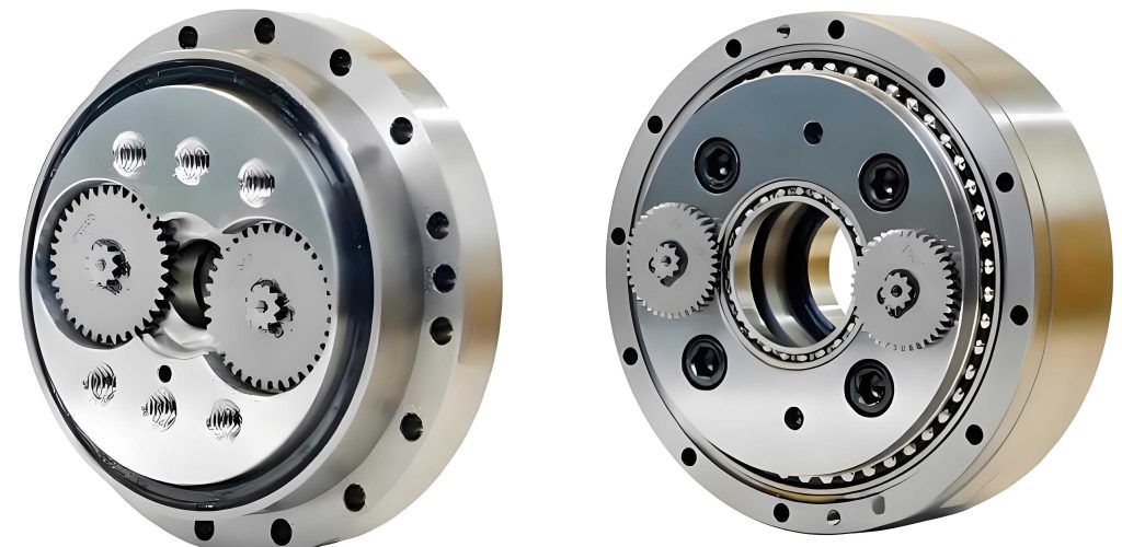
The rotary vector reducer is a sophisticated two-stage speed reduction mechanism. It combines a first-stage planetary gear train with a second-stage cycloidal pin-wheel drive. This design inherits the prominent advantages of cycloidal drives, resulting in high reduction ratios, exceptional torsional stiffness, compact size, low backlash, and high transmission efficiency. The core of the second stage typically involves two or three cycloidal discs, often mounted 180 degrees apart on crankshafts, facilitating torque splitting and enhanced load capacity. The entire mechanism, including the input planetary stage and the output cycloidal stage, is integrated into a rigid, enclosed housing supported by main bearings.
To manage the assembly quality of the rotary vector reducer, a clear understanding of its dimensional relationships is fundamental. I derived the assembly dimension chain based on the kinematic and geometric constraints of its components. A simplified schematic focusing on the critical second-stage cycloidal drive is essential for this analysis.
The key dimensions involved are:
- $r_p$: Radius of the pin (needle roller).
- $R_p$: Radius of the pin distribution circle (the circle on which all pin centers lie).
- $a$: Theoretical eccentricity (the distance between the geometric center of the cycloidal disc and the geometric center of the pin housing assembly).
- $a_1$: Crankshaft eccentricity.
- $L_1$: Distance from the geometric center of the support plate (or output plate) to the center of its crankshaft bearing bore.
- $L_2$: Distance from the geometric center of the cycloidal disc to the center of its crankshaft bearing bore.
- $r_a$, $r_f$: Radius of the cycloidal disc’s addendum circle and root circle, respectively.
Ignoring bearing clearances for the initial tolerance model, the fundamental relationships from the dimension chain are:
$$
a = L_1 + a_1 – L_2
$$
$$
\Delta_1 = r_a – r_f – r_p
$$
$$
\Delta_2 = R_p + r_p – r_a
$$
The first equation ($a = L_1 + a_1 – L_2$) is paramount as it defines the theoretical eccentricity, which directly governs the meshing action between the cycloidal disc and the pins. Any deviation from the nominal value of $a$ affects the conjugate meshing condition, potentially leading to increased backlash, binding, or uneven load distribution among the many simultaneously meshing teeth.
Establishing the 3DCS Tolerance Simulation Model
The 3DCS software, fully integrated within CATIA V5, provides a powerful platform for 3D variation analysis. My simulation model for the rotary vector reducer was built systematically, encompassing three core elements: the geometric part models, the assigned part tolerances, and the defined assembly sequences with measurement parameters.
I began by creating detailed 3D solid models of all critical components for an RV-40E-81 type reducer using CATIA. Particular attention was paid to the cycloidal disc. Instead of a simple extrusion, I modeled it parametrically based on its generated trochoidal equation, ensuring each tooth profile was an independent feature. This is crucial for applying individual tooth profile errors later. The parametric equations for the cycloidal tooth profile, incorporating modification methods like equidistant and moving distance modifications, are given by:
$$
\begin{aligned}
x &= (R_p + \Delta r_p) \sin \psi – a \sin(z_c \psi) + (r_p + \Delta r_{rp}) \times \\
&\left[ \left(1 – \frac{1}{K^2}\right) \sin\left(z_c \psi – \arctan\left(\frac{\sin(z_c \psi)}{K – \cos(z_c \psi)}\right)\right) – \frac{1}{K} \sin\left(\arctan\left(\frac{\sin(z_c \psi)}{K – \cos(z_c \psi)}\right)\right) \right] \\
y &= (R_p + \Delta r_p) \cos \psi – a \cos(z_c \psi) + (r_p + \Delta r_{rp}) \times \\
&\left[ \left(1 – \frac{1}{K^2}\right) \cos\left(z_c \psi – \arctan\left(\frac{\sin(z_c \psi)}{K – \cos(z_c \psi)}\right)\right) – \frac{1}{K} \cos\left(\arctan\left(\frac{\sin(z_c \psi)}{K – \cos(z_c \psi)}\right)\right) \right] \\
K &= \frac{R_p z_c}{a z_p}
\end{aligned}
$$
Where $\psi$ is the rolling angle parameter, $z_c$ is the number of teeth on the cycloidal disc, $z_p$ is the number of pins, $\Delta r_{rp}$ is the moving distance modification, and $\Delta r_p$ is the equidistant modification.
Next, I applied dimensional and geometric tolerances to the parts based on preliminary design specifications and machining capabilities. The tolerances for key components before optimization are summarized in the table below:
| Component | Feature | Nominal Size (mm) | Deviation (mm) | Tolerance (mm) |
|---|---|---|---|---|
| Pin Housing | Main Bearing Bore Coaxiality | – | 0 | 0.010 |
| Pin Housing | Pin Hole True Position (Circular) | – | 0 | 0.006 |
| Pin Housing | Pin Distribution Circle Radius $R_p$ | 66 | 0 | 0.002 |
| Pin | Pin Radius $r_p$ | 3 | -0.003 | 0.002 |
| Support/Output Plate | Crankshaft Bore Center Distance $L_1$ | 72 | 0 | 0.012 |
| Crankshaft | Crankshaft Eccentricity $a_1$ | 1.25 | 0 | 0.006 |
| Cycloidal Disc | Crankshaft Bore Center Distance $L_2$ | 72 | 0 | 0.012 |
| Cycloidal Disc | Moving Distance Mod $\Delta r_{rp}$ | -0.014 | 0 | 0.004 |
| Cycloidal Disc | Equidistant Mod $\Delta r_p$ | -0.012 | 0 | 0.002 |
| Cycloidal Disc | Radial Runout (Tooth Ring) | – | 0.00375 | 0.0075 |
| Cycloidal Disc | Accumulative Pitch Error | – | 0.005 | 0.009 |
| – | Theoretical Eccentricity $a$ | 1.25 | 0 | 0.010 |
In 3DCS, geometric tolerances like coaxiality and true position were applied directly to the CAD features. Specific errors, such as the cycloidal disc’s tooth-to-tooth accumulated pitch error, were modeled by introducing small rotational deviations for each individual tooth profile feature relative to its theoretical position. The radial runout was simulated by offsetting the entire tooth ring from the disc’s geometric center. Profile errors from modifications were applied as surface deviations on the tooth flanks.
The assembly sequence was designed to mimic the actual workshop process. Parts were mated based on datums and functional interfaces—for instance, the pins were assembled into the pin housing based on their theoretical center circle, and the cycloidal disc was mounted onto the crankshaft bearings. Finally, I defined the critical measurement parameters: the eccentricity error (the actual distance between the cycloidal disc center and the pin housing center) and the tooth side clearance at the theoretical meshing points between the cycloidal disc and each individual pin. Ensuring a small but positive clearance is vital for lubrication and preventing binding due to thermal expansion or error stack-up.
Simulation, Optimization Results, and Analysis
With the complete 3DCS model, I performed Monte Carlo simulations. This method randomly generates thousands of part instances based on their defined tolerance distributions, assembles them virtually according to the sequence, and calculates the resulting measurement values. The statistical output, analyzed using the Six Sigma (6σ) principle, provided a clear picture of assembly yield and variation patterns. The initial simulation revealed significant issues. For example, approximately 3.78% of assemblies showed an eccentricity error outside the acceptable limits. More critically, the tooth side clearance analysis showed a high probability of interference or clearance below the minimum required 0.001 mm at several pin meshing positions (e.g., ~14.8% at pin 3, ~26.7% at pin 6). This highlighted the need for tolerance optimization.
I then conducted a sensitivity analysis to identify which part tolerances contributed most to the variation in the eccentricity error and the tooth side clearance. This information is key to cost-effective optimization, as it allows tightening only the most influential tolerances. The sensitivity results for eccentricity showed that four features were dominant:
| Rank | Feature | Contribution to Eccentricity Variation |
|---|---|---|
| 1 | Main Bearing Bore Coaxiality (Pin Housing) | 27.47% |
| 2 | Crankshaft Bore Center Distance $L_1$ (Plate) | 27.47% |
| 3 | Crankshaft Bore Center Distance $L_2$ (Cycloidal Disc) | 27.47% |
| 4 | Crankshaft Eccentricity $a_1$ | 17.58% |
Guided by this sensitivity analysis, I systematically adjusted the tolerances and, in some cases, the nominal deviations. The goal was to achieve a design where 100% of the simulated assemblies (within 6σ) met the performance criteria: eccentricity within specification and all tooth side clearances ≥ 0.001 mm. The optimized tolerance set is shown below:
| Component | Feature | Nominal Size (mm) | Deviation (mm) | Tolerance (mm) |
|---|---|---|---|---|
| Pin Housing | Main Bearing Bore Coaxiality | – | 0 | 0.005 |
| Pin Housing | Pin Hole True Position (Circular) | – | 0 | 0.005 |
| Pin Housing | Pin Distribution Circle Radius $R_p$ | 66 | -0.002 | 0.002 |
| Pin | Pin Radius $r_p$ | 3 | -0.006 | 0.001 |
| Support/Output Plate | Crankshaft Bore Center Distance $L_1$ | 72 | 0 | 0.010 |
| Crankshaft | Crankshaft Eccentricity $a_1$ | 1.25 | 0 | 0.004 |
| Cycloidal Disc | Crankshaft Bore Center Distance $L_2$ | 72 | 0 | 0.010 |
| Cycloidal Disc | Moving Distance Mod $\Delta r_{rp}$ | -0.014 | -0.002 | 0.002 |
| Cycloidal Disc | Equidistant Mod $\Delta r_p$ | -0.012 | 0 | 0.002 |
| Cycloidal Disc | Radial Runout (Tooth Ring) | – | 0.0024 | 0.0048 |
| Cycloidal Disc | Accumulative Pitch Error | – | 0.006 | 0.006 |
The post-optimization simulation confirmed a 100% assembly yield for the defined clearance criteria. Furthermore, the overall backlash of the rotary vector reducer, calculated from the cumulative effect of tooth clearances and eccentricity variation, was confirmed to be within the acceptable range of 0.25 to 1 arcminutes.
A more detailed sensitivity analysis on the tooth side clearance after optimization provided profound insights for manufacturing focus. The contribution of errors from the cycloidal disc and the pin set (housing and pins) were paramount, often accounting for 20-40% each at various pin locations. Within the cycloidal disc, the profile modification errors ($\Delta r_{rp}$, $\Delta r_p$) were the most significant contributors. For the pin set, the pin radius $r_p$ tolerance was highly influential. The main bearing bore coaxiality, while critical for eccentricity, showed a more moderate but consistent influence (9-18%) on side clearance. Interestingly, the impact of $L_1$, $L_2$, and $a_1$ on side clearance varied significantly depending on the specific pin meshing position, underscoring the complexity of the load distribution in a multi-tooth meshing rotary vector reducer.
Conclusion and Discussion
Through this detailed investigation, I have demonstrated a robust methodology for the tolerance analysis and optimization of the rotary vector reducer assembly. The integration of 3D parametric modeling in CATIA with advanced variation analysis in 3DCS provides a powerful virtual prototyping tool that surpasses the limitations of traditional 2D tolerance stack-up methods. This approach directly contributes to improving first-pass assembly yield by ensuring that the allocated part tolerances collectively guarantee the final product’s kinematic performance—specifically, controlled eccentricity, positive tooth clearance, and minimal backlash.
The key findings and implications are multi-fold. First, the assembly dimension chain equation $a = L_1 + a_1 – L_2$ is validated as the most critical constraint for the rotary vector reducer. The tolerances on $L_1$, $a_1$, and $L_2$ must be tightly coordinated and controlled, as evidenced by their high sensitivity. Second, the meshing condition between the cycloidal disc and the pins is extremely sensitive to the disc’s tooth profile modifications ($\Delta r_{rp}$, $\Delta r_p$) and the pin’s radius ($r_p$). This highlights the necessity for precise and consistent machining processes for these features. Third, the geometric accuracy of the pin housing, particularly the coaxiality of its main bearing bores, is fundamental as it influences both the eccentricity and the uniformity of tooth clearances around the entire rotary vector reducer.
The optimized tolerance set presented offers a viable blueprint for manufacturing. By tightening only the most sensitive tolerances (like main bore coaxiality, $a_1$, and profile modifications) and intelligently adjusting nominal deviations (e.g., for $r_p$ and $R_p$), performance can be assured without imposing unnecessarily strict and costly tolerances on all components. The sensitivity analysis results serve as a valuable guide for quality control, indicating which part features should be prioritized during inspection.
It is important to note that this model focused on the static assembly condition. A logical and necessary extension for future work would be to incorporate dynamic factors such as bearing internal clearances, thermal expansion effects, and elastic deformations under load. Integrating these factors into the 3DCS model would yield an even more comprehensive and realistic prediction of the rotary vector reducer‘s performance in real-world operating conditions, further closing the gap between virtual design and physical reality.