
In recent years, legged robotics has garnered significant attention due to its potential in traversing complex terrains. Among these, quadruped robots, often referred to as robot dogs, offer distinct advantages in stability, agility, and payload capacity compared to wheeled or tracked counterparts. This article presents the design and implementation of a vision-based autonomous line-following robot dog, utilizing the Raspberry Pi 4B as the central processing unit. The primary objective is to develop a cost-effective, modular robot dog capable of performing tasks such as line tracking, red marker detection, slope ascent and descent, and low-profile crawling through custom gait patterns. By integrating computer vision and precise servo control, this robot dog demonstrates a high degree of autonomy in structured environments.
The core innovation lies in the fusion of off-the-shelf hardware and open-source software to create a versatile platform. The robot dog employs a Raspberry Pi expansion board to manage multiple PWM and serial bus servos, a camera module for real-time image acquisition, and a custom power distribution system. The software stack leverages OpenCV for image processing, enabling robust line detection and color-based decision-making. This design not only simplifies development but also reduces production costs, making it accessible for educational and research applications. The following sections detail the system architecture, hardware components, software algorithms, and experimental validation, culminating in a discussion of future enhancements.
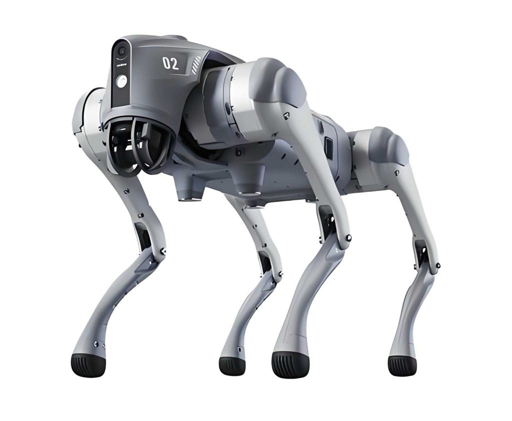
The overall system design of the robot dog is bifurcated into hardware and software subsystems, as illustrated in the conceptual diagram. The hardware encompasses the mechanical structure, actuation units, sensors, and control electronics, while the software governs perception, decision-making, and motion control. The robot dog’s body is designed with lightweight yet durable materials, ensuring agility and stability during dynamic movements. The limb configuration mimics biological quadrupeds, with three degrees of freedom per leg, allowing for omnidirectional movement. The head unit houses the camera, providing a frontal field of view for environmental perception.
| Component | Model/Specification | Function |
|---|---|---|
| Main Controller | Raspberry Pi 4B (4GB RAM) | Central processing, image analysis, servo control |
| Expansion Board | Waveshare Raspberry Pi Multi-Function Board | Power management, PWM/serial servo interfacing |
| Leg Servos | LX-224 Serial Bus Smart Servos (12 units) | Precise limb articulation with feedback |
| Head Servo | LFD-01M PWM Servo (1 unit) | Camera pan/tilt for gaze control |
| Camera Module | Raspberry Pi Camera Module v2 (8MP) | Image capture at 640×480 resolution |
| Power Source | Lithium Polymer Battery (11.1V, 2200mAh) | Dual-voltage supply for servos and Pi |
Hardware design focuses on interoperability and power efficiency. The Raspberry Pi 4B serves as the brain, executing high-level algorithms and communicating with peripherals via GPIO, I²C, and serial interfaces. A critical challenge is voltage regulation: the LX-224 servos require 6–8.4V, while the LFD-01M operates at 4.8–6V. The expansion board integrates a buck converter, accepting 5.5–15V input and providing stable 5V to the Pi and adjustable voltages to servo groups. This eliminates the need for multiple batteries, reducing weight and complexity. The camera module is configured to capture frames at 30 fps, with each image approximately 2.4 MB in size. Image size can be adjusted via the raspistill command to balance resolution and processing load. The mechanical frame is 3D-printed using PLA, optimizing strength-to-weight ratio. The robot dog’s dimensions are 300 mm in length, 200 mm in width, and 250 mm in height, ensuring a compact form factor suitable for indoor navigation.
Software design is centered on autonomous perception and control. The pipeline begins with image acquisition, followed by preprocessing, feature extraction, and action selection. OpenCV libraries facilitate real-time image manipulation. The core algorithm involves partitioning each captured frame into three regions of interest (ROIs): upper, middle, and lower. This reduces computational overhead by focusing on relevant areas. Color thresholds for white (line), red (marker), and black (background) are empirically determined based on ambient lighting conditions. Each pixel is classified using HSV color space segmentation, where thresholds define hue, saturation, and value ranges. For white detection, the condition can be expressed as:
$$ \text{White Pixel} = \begin{cases} 1 & \text{if } S_{\text{pixel}} < S_{\text{thresh}} \text{ and } V_{\text{pixel}} > V_{\text{thresh}} \\ 0 & \text{otherwise} \end{cases} $$
where $S_{\text{pixel}}$ and $V_{\text{pixel}}$ are saturation and value components, and $S_{\text{thresh}}$ and $V_{\text{thresh}}$ are predefined thresholds. Similarly, red detection uses a hue range around 0° and 180°, accounting for wraparound. After binarization, each ROI is downsampled into a matrix: initially 30×40 pixels are converted to a 3×6 binary matrix, where 1 denotes white and 0 denotes non-white. This is further reduced to a 3×3 matrix by averaging blocks, summarizing line position data. The robot dog’s decision logic is based on the distribution of 1s in this matrix. For instance, if the center column of the middle row has a 1, the robot dog moves forward; if left columns dominate, it turns left, and vice versa. The turning angle $\theta$ is proportional to the deviation $d$ from the center, calculated as:
$$ \theta = k_p \cdot d + k_d \cdot \frac{\Delta d}{\Delta t} $$
where $k_p$ and $k_d$ are proportional and derivative gains, implementing a PD controller for smooth corrections. When the white blob width exceeds a threshold (e.g., 50 pixels), indicating a wide line or intersection, the robot dog halts. Red marker detection triggers gait transitions: first detection initiates a slope-climbing gait, and third detection switches to a low-profile crawl. These gaits are preprogrammed sequences of servo angles, optimized for stability and energy efficiency.
| Gait Mode | Description | Servo Angle Range (Degrees) | Speed (cm/s) |
|---|---|---|---|
| Trot | Default walking gait, diagonal leg pairs move | ±45 from neutral | 15 |
| Slope Ascent | Increased stride height, forward lean | ±60 for front legs, ±30 for rear | 10 |
| Crawl | Low-profile, legs close to body | ±20 for all legs | 5 |
| Turn-in-Place | Opposite rotation of left/right leg groups | ±30 differential | 20°/s |
Experimental validation was conducted on a custom test track comprising straight lines, curves, slopes of 15° inclination, and red markers. The robot dog successfully completed 100 trials, with performance metrics logged. Line-following accuracy was measured as the percentage of time the robot dog remained within ±2 cm of the line center. On straight segments, accuracy reached 98%, while on curves with a radius of 50 cm, it dropped to 85% due to servo response latency. Slope navigation had a success rate of 90%, with failures occurring from slippage on steep inclines. The crawl gait reduced the robot dog’s height by 40%, enabling under-obstacle passage. Power consumption averaged 12W during operation, allowing for 45 minutes of continuous use. The table below summarizes key results.
| Task | Success Rate (%) | Average Completion Time (s) | Notes |
|---|---|---|---|
| Straight Line Following | 98 | 10 per 2m | High precision, minimal deviation |
| Curve Negotiation (50cm radius) | 85 | 15 per 90° turn | Overshoot observed in sharp turns |
| Slope Ascent/Descent (15°) | 90 | 20 per 1m slope | Gait transition crucial for stability |
| Red Marker Detection | 95 | N/A | False positives in bright light |
| Crawl Mode Obstacle Clearance | 88 | 30 per 1m | Limited speed, high stability |
Despite these achievements, several limitations were identified. The robot dog’s performance degrades in low-light or high-glare conditions, as color thresholds become less reliable. Additionally, the current PID controller for line following sometimes causes oscillations on wavy paths. Future work will integrate sensor fusion, adding an IMU for inertial measurement to improve slope detection and gait adaptation. Machine learning techniques, such as convolutional neural networks (CNNs), could enhance visual perception, allowing the robot dog to recognize more complex patterns and obstacles. Furthermore, energy efficiency can be improved by implementing dynamic voltage scaling for servos based on load. The modular design of this robot dog facilitates such upgrades, making it a platform for ongoing research in legged robotics.
In conclusion, this article detailed the development of a vision-based autonomous line-following robot dog using Raspberry Pi. The robot dog demonstrates robust performance in structured environments, executing tasks like line tracking, slope navigation, and crawling through integrated hardware and software. The use of OpenCV for image processing and custom gait algorithms enables adaptable behavior. While challenges remain in environmental robustness and control precision, the system provides a foundation for advanced autonomous robot dogs. By continuing to refine perception, control, and mechanical design, such robot dogs could see applications in search and rescue, industrial inspection, and assisted living. The open-source nature of the components encourages community-driven innovation, paving the way for more capable and affordable quadruped robots.