
In recent years, the development of robotics for hazardous environments has gained significant attention, particularly in the coal mining industry. The challenging conditions underground, including unstable terrain, limited visibility, and the presence of explosive gases, necessitate the use of advanced robotic systems to assist or replace human workers. Among various robotic platforms, the quadruped robot, often referred to as a robot dog, has emerged as a promising solution due to its inherent stability, adaptability, and ability to traverse complex landscapes. This article presents a comprehensive design and experimental verification of a multifunctional quadruped robot system tailored for coal mine applications, leveraging digital twin technology to enhance performance, monitoring, and control. The integration of virtual and physical dimensions through digital twins allows for real-time simulation, planning, and oversight, addressing limitations such as functional singularity and poor adaptability in existing systems.
The core of this work involves the development of a quadruped robot capable of performing tasks like inspection, transportation, and drilling in underground mines. Starting with fundamental theoretical analyses, including mechanical design, kinematic modeling, and gait planning, we proceed to investigate key technologies for autonomous perception, decision-making, and control. A digital twin framework is constructed, comprising virtual simulation and planning systems, a physical robot system, and a virtual monitoring interface. Experimental results demonstrate that the quadruped robot exhibits robust structural integrity, multifunctional capabilities, and excellent adaptation to complex geological conditions, enabling environment perception, obstacle avoidance, and task execution in unknown settings. The virtual systems provide essential support for autonomous operations, offering 3D state monitoring and remote human-robot interaction, thereby contributing to the advancement of intelligent and unmanned mining practices.
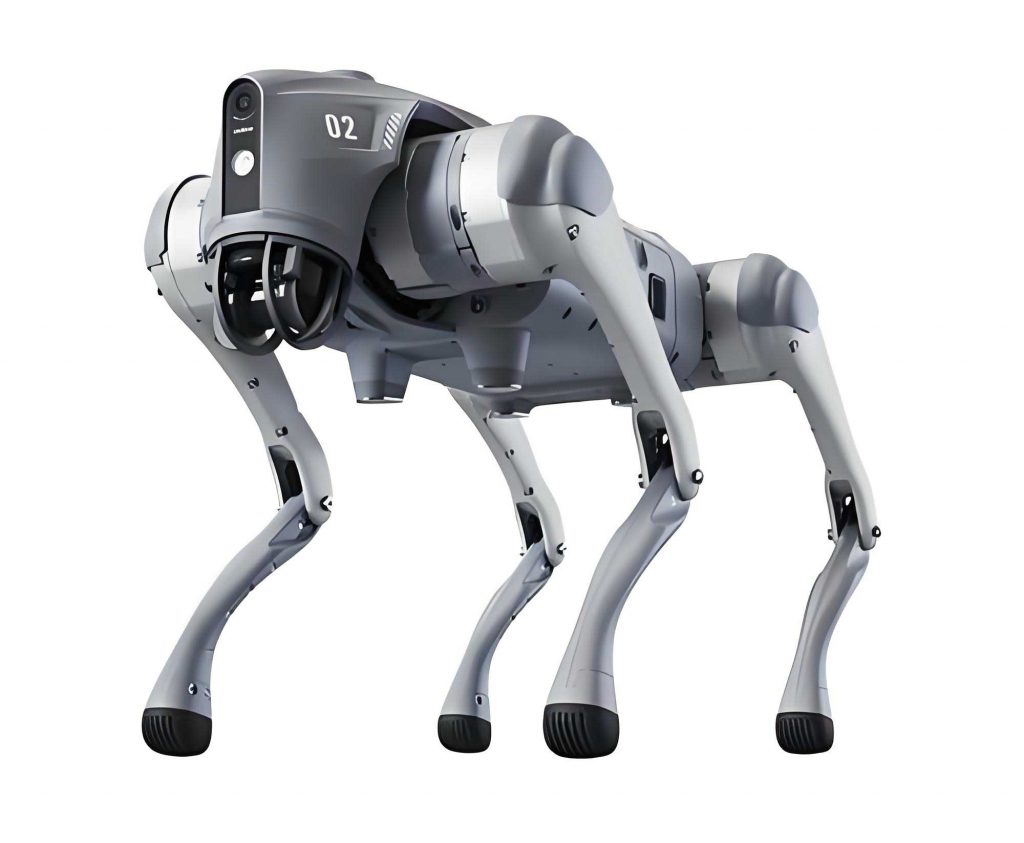
The mechanical design of the quadruped robot prioritizes stability and maneuverability in confined spaces. The body adopts a square configuration, with legs symmetrically positioned at each corner to form an enclosed structure. Inspired by insect leg anatomy and existing robotic models, the leg segments—comprising the hip, thigh, and shank—are designed with a length ratio of 0.09:0.455:0.455. Each leg features three rotational joints: a base joint at the hip for horizontal rotation, a hip joint for vertical movement, and a knee joint for additional flexibility. The dimensions are optimized for use with 35 kg UART serial bus servos, ensuring sufficient torque for load-bearing and dynamic motions. The thigh segment measures 273 mm between rotation axes, with small U-brackets adding 36 mm offsets, resulting in an effective length of 201 mm between brackets. Similarly, the shank extends 273 mm from the rotation axis to the foot end, incorporating a 27 mm offset from a large U-bracket and a 15 mm silicone ball at the foot for enhanced grip. This design facilitates a balanced weight distribution and efficient force application during locomotion.
Kinematic modeling is essential for controlling the robot dog’s movements. The forward kinematics computes the foot-end position based on joint angles, while inverse kinematics derives joint angles from desired foot-end coordinates. A coordinate system is established, including a body-fixed frame {B} at the geometric center, a world frame {W}, and transitional frames {Ti} for each leg. The Denavit-Hartenberg (D-H) parameters are summarized in the table below, defining the relationships between consecutive links.
| Link i | ai-1 | αi-1 | di | θi |
|---|---|---|---|---|
| 1 | 0 | 0 | 0 | θ1 |
| 2 | L1 | 90° | 0 | θ2 |
| 3 | L2 | 0 | 0 | θ3 |
| Foot | L3 | 0 | 0 | — |
Using the D-H convention, the transformation matrix between frames {Ti-1} and {Ti} is given by:
$$^{i-1}T_i = \begin{bmatrix}
\cos \theta_i & -\sin \theta_i & 0 & a_{i-1} \\
\sin \theta_i \cos \alpha_{i-1} & \cos \theta_i \cos \alpha_{i-1} & -\sin \alpha_{i-1} & -d_i \sin \alpha_{i-1} \\
\sin \theta_i \sin \alpha_{i-1} & \cos \theta_i \sin \alpha_{i-1} & \cos \alpha_{i-1} & d_i \cos \alpha_{i-1} \\
0 & 0 & 0 & 1
\end{bmatrix}$$
For a single leg, the forward kinematics equations yield the foot-end position (x, y, z) in the transitional frame:
$$x = c_1 [L_1 + c_2 L_2 + (c_2 c_3 – s_2 s_3) L_3]$$
$$y = s_1 [L_1 + c_2 L_2 + (c_2 c_3 – s_2 s_3) L_3]$$
$$z = s_2 L_2 + (s_2 c_3 + c_2 s_3) L_3$$
where \(c_i = \cos \theta_i\) and \(s_i = \sin \theta_i\). The inverse kinematics solves for joint angles given the foot-end coordinates \(P_0 = (x, y, z)^T\):
$$\theta_1 = \arctan \left( \frac{y}{x} \right)$$
$$\theta_2 = \arctan \left( \frac{z}{\sqrt{x^2 + y^2} – L_1} \right) + \arccos \left( \frac{u^2 + L_2^2 – L_3^2}{2 u L_2} \right)$$
$$\theta_3 = -\arccos \left( \frac{u^2 + L_2^2 – L_3^2}{2 L_2 u} \right) – \arccos \left( \frac{u^2 – L_2^2 + L_3^2}{2 u L_3} \right)$$
with \(u = \sqrt{ \left( \sqrt{x^2 + y^2} – L_1 \right)^2 + z^2 }\). These equations enable precise control of the quadruped robot’s leg movements during various tasks.
Gait planning is critical for stable locomotion. We employ a static gait with a 3-4-2-1 footfall sequence, which maximizes stability margin. The stability criterion is based on the absolute stability margin, ensuring the projection of the center of gravity (CoG) remains within the support polygon. For this sequence, the robot alternates between double-support triangles during leg swings. The CoG trajectory is planned using polynomial functions to minimize jerks and maintain balance. During the swing phase, three legs support the body while one leg moves, and during the CoG adjustment phase, all four legs adjust to shift the CoG into the double-support triangle. The trajectory for CoG adjustment from an initial position to a target \((x_0, y_0)\) over time \(T\) is described by:
$$x(t) = \frac{6x_0}{T^5} t^5 – \frac{15x_0}{T^4} t^4 + \frac{10x_0}{T^3} t^3$$
$$y(t) = \frac{6y_0}{T^5} t^5 – \frac{15y_0}{T^4} t^4 + \frac{10y_0}{T^3} t^3$$
for \(t \in [0, T]\). Online motion planning incorporates a state machine triggered by time and events (e.g., foot contact), allowing real-time adaptation to terrain changes. The phase sequence is adjusted based on the desired velocity direction to optimize efficiency, as summarized in the following table.
| Primary Direction | Phase Sequence |
|---|---|
| +Y axis | CoG adjustment > Swing leg 3 > Swing leg 4 > CoG adjustment > Swing leg 2 > Swing leg 1 |
| -Y axis | CoG adjustment > Swing leg 1 > Swing leg 2 > CoG adjustment > Swing leg 4 > Swing leg 3 |
| +X axis | CoG adjustment > Swing leg 4 > Swing leg 1 > CoG adjustment > Swing leg 3 > Swing leg 2 |
| -X axis | CoG adjustment > Swing leg 2 > Swing leg 3 > CoG adjustment > Swing leg 1 > Swing leg 4 |
Autonomous perception and decision-making are enabled through SLAM (Simultaneous Localization and Mapping) using a 2D LiDAR sensor. This technology allows the quadruped robot to construct maps of unknown environments while tracking its position. Navigation is achieved through dead reckoning, where encoder data from motors estimate the robot’s velocity and orientation. For a differential drive model, the linear and angular velocities are computed as:
$$v_l = \frac{(E_{l_c} – E_{l_p})}{T_e} \times \frac{\pi}{180} \, \text{rad/s}$$
$$v_r = \frac{(E_{r_c} – E_{r_p})}{T_e} \times \frac{\pi}{180} \, \text{rad/s}$$
$$v_k = \frac{(v_l + v_r)}{2} \, \text{m/s}$$
$$\omega_k = \frac{(v_r – v_l)}{D} \, \text{rad/s}$$
where \(E_{l_c}\) and \(E_{r_c}\) are current encoder values, \(E_{l_p}\) and \(E_{r_p}\) are previous values, \(T_e\) is the sampling time, and \(D\) is the distance between legs. The position and orientation updates are:
$$\Delta s = v_k T_e$$
$$\Delta \theta = \omega_k T_e$$
$$x_{k+1} = x_k + \Delta s \cos \left( \theta_k + \frac{\Delta \theta}{2} \right)$$
$$y_{k+1} = y_k + \Delta s \sin \left( \theta_k + \frac{\Delta \theta}{2} \right)$$
$$\theta_{k+1} = \theta_k + \Delta \theta$$
The hardware system centers on a Raspberry Pi 4B running Raspberry Pi OS (64-bit), programmed in Python 3.9. Actuation is handled by 35 kg bus servos, with an MPU6050 inertial measurement unit for attitude sensing and HC-12 wireless modules for communication. The software architecture modularizes functionalities such as gait planning, sensor interfacing, and communication, ensuring robust real-time operation. A table below outlines the key hardware components.
| Component | Specification | Function |
|---|---|---|
| Raspberry Pi 4B | ARM-based SBC | Main controller |
| Bus Servos | 35 kg torque | Leg joint actuation |
| MPU6050 | 6-axis IMU | Attitude sensing |
| HC-12 Module | 433 MHz wireless | Serial communication |
| LiDAR | 2D scanning | Environment mapping |
The digital twin aspect involves virtual simulation and monitoring systems built in Unity3D and Webots. These platforms allow for offline planning, virtual debugging, and real-time monitoring. In Unity3D, the robot model is imported, and inverse kinematics solvers interpolate joint angles for smooth animations. Modes include single-leg control (angle and float modes for keyframe-based trajectory planning) and multi-leg control (gait, posture, and autonomous modes for complex behaviors). For instance, in single-leg float mode, the foot-end position is adjusted via a GUI, while multi-leg gait mode generates periodic motions like crawling with user-defined parameters. The virtual monitoring system provides a 3D visualization of the robot’s state, enabling remote operation and data analysis through a human-machine interface.
Experiments validate the quadruped robot’s performance in various scenarios. On flat terrain, the robot maintains stable posture with pitch, roll, and yaw angles fluctuating within ±0.5° and ±1°, respectively. On complex surfaces模拟ated by randomly placed obstacles (e.g., 200 mm × 100 mm × 100 mm blocks), the robot adapts its foot trajectories to avoid collisions and adjusts its body height for optimal stability. In slope climbing tests on a 15° incline, the robot successfully orients its body parallel to the surface, with the pitch angle tracking the slope accurately. Additional functionalities, such as drilling and object transportation, demonstrate the versatility of this quadruped robot. The digital twin systems facilitate these tests by providing pre-execution simulations and real-time feedback, reducing the risk of physical failures.
In conclusion, the integration of digital twin technology with a multifunctional quadruped robot significantly enhances its applicability in coal mine environments. The robot dog exhibits robust mechanical design, precise kinematic control, and adaptive gait planning, enabling reliable operation in unstructured terrains. Key technologies like SLAM-based perception and dead reckoning navigation support autonomous decision-making, while the virtual systems offer comprehensive monitoring and planning capabilities. Future work will focus on explosion-proof modifications to meet safety standards in gaseous environments, further advancing toward fully intelligent and unmanned mining operations. The successful implementation of this quadruped robot system underscores the potential of legged robotics in transforming industrial automation, with digital twins serving as a bridge between physical and virtual realms for continuous improvement and innovation.