
In the field of precision mechanical transmission, the strain wave gear, also known as a harmonic drive, plays a pivotal role due to its high reduction ratio, compactness, and minimal backlash. As a key component, the flexspline undergoes significant elastic deformation during operation, making its dynamic behavior critical to the overall performance and longevity of the strain wave gear system. Modal analysis, a fundamental method in structural dynamics, is employed to investigate the natural frequencies and mode shapes of a structure. This is essential to avoid resonance, which can lead to accelerated fatigue failure and reduced service life. In this article, I will present a comprehensive finite element modal analysis of a strain wave gear flexspline using ANSYS software, aiming to elucidate its vibrational characteristics under working conditions. The insights gained can inform design improvements and ensure reliable operation.
The dynamic response of any mechanical structure, including a strain wave gear flexspline, is governed by its inherent vibrational properties. When subjected to time-varying loads, such as those from an unbalanced rotor or operational forces, the structure may experience resonance if the excitation frequency coincides with one of its natural frequencies. Resonance amplifies vibrations, leading to excessive stresses and potential failure. Therefore, conducting a modal analysis is a prerequisite for robust design. The finite element method (FEM) provides a powerful numerical tool to discretize complex geometries and solve the underlying equations of motion. For a linear system, the general equation of motion can be expressed as:
$$ M\ddot{x} + C\dot{x} + Kx = F(t) $$
where \( M \) is the mass matrix, \( C \) is the damping matrix, \( K \) is the stiffness matrix, \( x \) is the displacement vector, and \( F(t) \) is the external force vector. For free vibration analysis, which forms the basis of modal analysis, damping and external forces are neglected, simplifying the equation to:
$$ M\ddot{x} + Kx = 0 $$
Assuming harmonic motion of the form \( x = \phi e^{i\omega t} \), where \( \phi \) is the mode shape vector and \( \omega \) is the circular frequency, we arrive at the generalized eigenvalue problem:
$$ (K – \omega^2 M)\phi = 0 $$
Solving this eigenvalue problem yields the natural frequencies \( f_n = \omega_n / 2\pi \) and corresponding mode shapes \( \phi_n \) of the structure. These parameters are intrinsic properties dependent on mass distribution and stiffness. For the strain wave gear flexspline, understanding these modes is crucial as it operates under cyclic deformation induced by the wave generator.
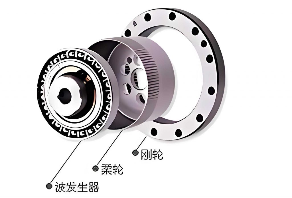
The first step in my finite element analysis involved creating an accurate geometric model of the strain wave gear flexspline. I utilized a parametric CAD software, specifically Pro/ENGINEER, to design the flexspline with all relevant features, including the thin-walled cup structure, external teeth, and mounting flange. The geometry was carefully crafted to reflect typical dimensions used in industrial strain wave gear applications. Key parameters, such as the number of teeth, wall thickness, and overall length, were defined to ensure the model’s fidelity. After completing the solid model, I exported it in a neutral format (e.g., STEP or IGES) and imported it into the ANSYS Workbench environment for subsequent analysis. This seamless integration between CAD and CAE tools is vital for efficient simulation workflows.
Upon importing the geometry, I proceeded to define the material properties for the flexspline. Commonly, strain wave gear flexsplines are manufactured from high-strength alloy steels to withstand cyclic stresses. I assigned a linear elastic isotropic material model with the following properties, as summarized in Table 1.
| Property | Symbol | Value | Unit |
|---|---|---|---|
| Young’s Modulus | \( E \) | 210 | GPa |
| Poisson’s Ratio | \( \nu \) | 0.3 | – |
| Density | \( \rho \) | 7850 | kg/m³ |
| Yield Strength | \( \sigma_y \) | ≥ 800 | MPa |
Next, I generated the finite element mesh. Given the complex geometry of the strain wave gear flexspline, particularly the small, numerous teeth, a hybrid meshing strategy was employed. I used higher-order tetrahedral elements (SOLID186 in ANSYS) for their ability to conform to irregular shapes. To ensure accuracy in stress concentration regions, such as the tooth roots and the fillet area connecting the cup to the flange, I applied local mesh refinement. The global element size was controlled, and a bias was introduced to transition from a coarse mesh in the cylindrical body to a fine mesh in the toothed region. The final mesh statistics are presented in Table 2. A well-constructed mesh is fundamental for capturing the true dynamic behavior of the strain wave gear component.
| Metric | Value |
|---|---|
| Number of Nodes | ~452,000 |
| Number of Elements | ~289,000 |
| Element Type | 10-node Tetrahedral (SOLID186) |
| Average Element Quality (Skewness) | 0.21 |
With the meshed model ready, I set up the modal analysis. In ANSYS, I selected the “Modal” analysis system. Boundary conditions are crucial in modal analysis as they simulate the physical constraints of the strain wave gear flexspline during operation. Typically, the flange end of the flexspline is fixed to a rigid structure. Therefore, I applied a fixed support constraint on the mounting surface of the flange, restricting all degrees of freedom (translational and rotational). The internal surface where the wave generator contacts the flexspline was left free, allowing it to deform as it would under the action of the elliptical wave generator in a real strain wave gear assembly. No external loads were applied, as this is a free vibration analysis to extract natural frequencies and mode shapes.
For the solution phase, I needed to choose an appropriate eigenvalue extraction method. Given the relatively large model size of the strain wave gear flexspline, the Block Lanczos method was selected. This method is efficient for extracting a subset of modes from large models, which is ideal since we are primarily interested in the lower-order modes that are most susceptible to excitation. I requested the solver to extract the first 10 modes and to perform modal expansion to calculate element results for post-processing. The solver equations for the Block Lanczos method iteratively solve the eigenvalue problem derived from the finite element matrices. The generalized eigenvalue problem can be restated for the iterative solver as finding \( \lambda = \omega^2 \) such that:
$$ \text{det}(K – \lambda M) = 0 $$
The solution converged successfully, and the results were available for review.
The primary output of the modal analysis is the set of natural frequencies and their associated mode shapes. For the strain wave gear flexspline, the first ten natural frequencies were extracted and are listed in Table 3 along with a detailed description of the predominant deformation pattern observed in each mode. It is important to note that these frequencies are for the constrained configuration (flange fixed) and represent the inherent dynamic properties of the structure.
| Mode Number | Natural Frequency, \( f_n \) (Hz) | Description of Mode Shape (Primary Deformation) |
|---|---|---|
| 1 | 173.25 | Rigid-body-like translation of the free end primarily along the X-axis (radial direction relative to gear axis). |
| 2 | 173.76 | Rigid-body-like translation of the free end primarily along the Z-axis (axial direction along the gear axis). |
| 3 | 281.46 | Combined bending deformation involving simultaneous X and Z directional displacements of the cup wall. |
| 4 | 281.48 | Pure torsional deformation about the Z-axis (gear axis), with the free end rotating relative to the fixed flange. |
| 5 | 441.09 | Bending deformation about the X-axis, causing the cup to tilt. |
| 6 | 753.74 | A complex mode combining rotation about the X-axis and Z-axis, exhibiting a twisted shape. |
| 7 | 753.92 | Torsional vibration mode about the Z-axis with a higher nodal diameter pattern compared to Mode 4. |
| 8 | 1374.7 | Higher-order torsional vibration about the X-axis, involving significant distortion of the tooth ring. |
| 9 | 1375.2 | Superposition of torsional vibrations about both X and Z axes, resulting in a complex warping mode. |
| 10 | 2852.2 | Combination of high-order longitudinal (axial) vibration and torsional vibration, showing severe local deformation near the teeth. |
The results reveal several interesting patterns. The first two modes are very close in frequency (173.25 Hz and 173.76 Hz) and represent fundamental translations. This near-degeneracy is common in axisymmetric structures with slight geometric imperfections or asymmetric constraints. Modes 3 and 4 are also nearly identical in frequency (~281.46-281.48 Hz), indicating a pair of closely spaced bending and torsional modes. The frequency separation increases significantly from the fifth mode onward. A critical observation is the emergence of pure and coupled torsional vibrations in higher modes (Modes 7, 8, 9, 10). Torsional vibrations in a strain wave gear flexspline are particularly concerning as they can induce alternating shear stresses in the thin wall and tooth roots, potentially accelerating fatigue crack initiation.
To assess the risk of resonance, one must compare these natural frequencies with the potential excitation frequencies present in the strain wave gear system. The primary source of dynamic excitation in a strain wave gear is the rotating wave generator. Its rotational speed, \( N \) (in RPM), generates an excitation frequency \( f_{ex} = N / 60 \) Hz. For a typical strain wave gear application, the motor speed might be in the range of 1000 to 3000 RPM, resulting in \( f_{ex} \) between approximately 16.7 Hz and 50 Hz. Additionally, tooth meshing frequencies may be present. The fundamental meshing frequency is given by:
$$ f_{mesh} = N_{teeth} \times \frac{N_{wave generator}}{60} $$
where \( N_{teeth} \) is the number of teeth on the flexspline. For a common strain wave gear with \( N_{teeth} = 200 \) and \( N_{wave generator} = 3000 \) RPM, \( f_{mesh} = 200 \times 50 = 10,000 \) Hz. While this is higher than the extracted natural frequencies, sub-harmonics could exist. Crucially, the lowest natural frequency of the flexspline from our analysis is 173.25 Hz. Comparing this with the typical excitation frequency range (16.7-50 Hz), we find a significant margin:
$$ \text{Frequency Ratio} = \frac{f_{n1}}{f_{ex}} = \frac{173.25}{50} \approx 3.47 $$
Since the lowest natural frequency is more than three times higher than the maximum expected operational excitation frequency, the risk of resonance in this strain wave gear assembly is minimal. This margin provides a safety factor against unforeseen higher-frequency disturbances.
Further insight can be gained by analyzing the effective mass participation for each mode. This metric indicates how much of the total mass is mobilized in each vibrational direction for a given mode. While a full table is extensive, a summary of the dominant directions for the first few modes reinforces the descriptions in Table 3. For instance, Mode 1 has a high effective mass in the X-direction, Mode 2 in the Z-direction, and Mode 4 in the rotational direction about Z. This information is vital for seismic or base excitation analyses but confirms the primary deformation patterns identified.
The finite element model’s accuracy can be conceptually verified by checking the relationship between frequency, stiffness, and mass. For a simple cantilever beam approximation of the flexspline cup, the fundamental bending frequency can be estimated using:
$$ f_1 \approx \frac{1}{2\pi} \sqrt{\frac{3EI}{L^3 m_{eff}}} $$
where \( E \) is Young’s modulus, \( I \) is the area moment of inertia of the cup cross-section, \( L \) is the effective length, and \( m_{eff} \) is the effective mass. Plugging in approximate values for the strain wave gear flexspline geometry yields an order-of-magnitude estimate close to the computed first bending mode frequency (Mode 3 at ~281 Hz), lending credibility to the FEM results.
In designing a strain wave gear, avoiding resonance is not the only concern. Even if direct resonance is avoided, operating near a natural frequency can lead to increased dynamic amplification. The dynamic magnification factor \( D \) for a single-degree-of-freedom system is given by:
$$ D = \frac{1}{\sqrt{(1 – r^2)^2 + (2\zeta r)^2}} $$
where \( r = f_{ex} / f_n \) is the frequency ratio and \( \zeta \) is the damping ratio. For our strain wave gear flexspline, with \( r \approx 0.05 \) to 0.29 for the first mode, and assuming light structural damping (\( \zeta \approx 0.01 \)), the magnification factor \( D \) remains very close to 1, indicating negligible dynamic amplification. This further assures the design’s safety from resonant vibration effects.
However, the modal analysis also highlights potential areas for design enhancement of the strain wave gear. The high-frequency torsional modes (e.g., Mode 8 at 1374.7 Hz) involve significant deformation in the tooth region. While these may not be excited under normal operation, they could be relevant during transient events like startup, shutdown, or under shock loads. To improve durability, one might consider subtle geometric modifications, such as optimizing the fillet radius at the tooth root or adding slight reinforcement ribs to the cup wall, to shift these torsional frequencies higher or reduce the stress concentration factors. The relationship between natural frequency and design parameters can be explored through parametric studies in ANSYS. For instance, the natural frequency is proportional to the square root of stiffness over mass: \( f_n \propto \sqrt{K/M} \). Increasing wall thickness increases both stiffness \( K \) and mass \( M \), but typically stiffness increases more rapidly, leading to higher natural frequencies.
Material selection also plays a role. Using a material with a higher specific stiffness ( \( E/\rho \) ) would raise all natural frequencies for the same geometry. For advanced strain wave gear applications, materials like titanium alloys or composites could be investigated using similar modal analysis techniques to evaluate their dynamic performance benefits.
In conclusion, the finite element modal analysis of the strain wave gear flexspline has been successfully conducted. I established a detailed 3D model, applied appropriate boundary conditions, and utilized the Block Lanczos method to extract the first ten natural frequencies and mode shapes. The results demonstrate a substantial gap between the lowest natural frequency (173.25 Hz) and the expected operational excitation frequencies, effectively eliminating the risk of resonance. The analysis also revealed the presence of critical torsional vibration modes at higher frequencies, which provides valuable insight for future design refinements of the strain wave gear component. This work underscores the importance of dynamic analysis in the design process of precision mechanical elements like the strain wave gear flexspline, ensuring reliability and longevity in demanding applications. Future work could involve experimental modal analysis for validation, coupled structural-thermal analysis, or transient dynamic analysis to simulate the actual meshing process within the complete strain wave gear assembly.