
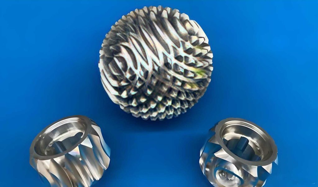
In my extensive experience within precision manufacturing, the production of spherical gears has always presented a unique set of challenges. These components, characterized by their complex curvilinear tooth profiles that must mesh seamlessly across multiple axes, are critical in advanced mechanical systems such as robotic joints, aerospace actuators, and specialized transmission units. For years, our facility struggled with an inefficient, time-consuming method for machining these spherical gears. The traditional approach, which I oversaw directly, involved painstakingly cutting each tooth individually on a milling machine. This required the workpiece to be constantly pivoted and indexed to approximate the spherical root contour, a manual and labor-intensive process that severely limited our productivity and consistency. The breakthrough came when we re-engineered the entire machining strategy, shifting to a generating process on a gear hobbing machine. This innovation not only boosted our efficiency by over twentyfold but also guaranteed exceptional quality, opening new avenues for the reliable mass production of spherical gears.
The core of the old method’s inefficiency lay in its discrete, non-continuous cutting path. Each tooth space was milled separately. To achieve the necessary spherical root form, the workpiece had to be rotated incrementally around its polar axis after each cut, a process governed by complex trigonometric calculations and prone to cumulative errors. The setup was fragile, and the cutting forces often caused deflections, leading to inaccuracies in the tooth flank geometry. We frequently encountered issues with surface finish and profile deviation, which necessitated lengthy secondary finishing operations. The entire cycle for a single spherical gear could take upwards of several hours, making it economically unviable for anything beyond prototype quantities. This experience solidified my understanding that a continuous generating process, similar to that used for cylindrical gears but adapted for spherical geometry, was the key to advancement.
The transformative solution we implemented involves a dedicated setup on a standard gear hobbing machine. The spherical gear blank is mounted onto a specially designed mandrel, which allows for precise lateral adjustment to align the workpiece’s pitch sphere center with the machine’s rotational axis. This mandrel is then secured between a universal dividing head and the machine’s tailstock center, both fixed to a secondary rotary table attached to the hobbing machine’s main saddle. The heart of the system is the synchronized motion. The rotary motion of the hobbing cutter is linked to the workpiece’s rotation via a universal joint and a train of change gears. This kinematic chain ensures a strict angular relationship between the cutter and the workpiece, which is fundamental for generating the correct spherical gear tooth profile.
The mathematical foundation for machining a spherical gear using a hob is profound. The relationship between the hob rotation and the workpiece rotation is defined by the gear ratio, which depends on the number of starts on the hob and the desired number of teeth on the spherical gear. If \( N_h \) is the number of hob starts and \( Z_s \) is the number of teeth on the spherical gear, the basic kinematic equation for the generating process is:
$$ \frac{\omega_w}{\omega_h} = \frac{N_h}{Z_s} $$
where \( \omega_w \) is the angular velocity of the workpiece and \( \omega_h \) is the angular velocity of the hob. This ratio is physically established by the change gear train. However, for a spherical gear, the hob must be tilted to match the local spiral angle at the point of contact, which varies across the tooth profile. The hob axis is first set vertically and then swiveled by an angle \( \beta \) corresponding to the mean spiral angle of the spherical gear tooth. This angle is derived from the spherical geometry of the pitch surface. For a spherical gear with pitch sphere radius \( R \), and a nominal module \( m_n \), the spiral angle \( \beta \) at a given cone distance \( R_c \) can be approximated by:
$$ \sin \beta = \frac{m_n \cdot Z_s}{2 R \cdot \cos \alpha_n} $$
where \( \alpha_n \) is the normal pressure angle. The true generation of the spherical profile is achieved by the compound motion: the synchronized rotation of hob and workpiece (generating motion) combined with the slow, continuous rotation of the entire secondary table (the workpiece assembly) around a vertical axis that passes through the center of the pitch sphere. This is the pivotal innovation. By turning the handle connected to the secondary table’s worm gear, the workpiece’s axis traces a cone relative to the hob, thereby sweeping out the spherical tooth root and flank. The instantaneous relative position between the hob and a point on the spherical gear blank is critical and can be modeled in 3D space. Let us define a coordinate system with origin at the center of the spherical gear’s pitch sphere. The hob cutter, with its axis tilted, can be represented as a series of cutting edges in space. The locus of points generated by the interaction of this moving hob and the rotating workpiece satisfies the equation of a spherical involute or a similar conjugate profile. The surface equation for the generated spherical gear tooth flank can be expressed parametrically. For a generating roll angle \( \phi \), and a parameter \( u \) along the tooth profile, the coordinates (X, Y, Z) of a point on the tooth surface are given by complex transformations involving rotation matrices. A simplified representation for the family of hob cutter surfaces in the workpiece coordinate system is:
$$ \begin{bmatrix} X \\ Y \\ Z \\ 1 \end{bmatrix} = \mathbf{T}_{wh}(\phi) \cdot \mathbf{T}_{hg}(\theta) \cdot \begin{bmatrix} x_h(u, \theta) \\ y_h(u, \theta) \\ z_h(u, \theta) \\ 1 \end{bmatrix} $$
Here, \( \mathbf{T}_{wh} \) is the homogeneous transformation matrix from the hob coordinate system to the workpiece system, dependent on the generating roll angle \( \phi \). \( \mathbf{T}_{hg} \) is the transformation due to the hob’s tilt and swivel settings. The vector \( [x_h, y_h, z_h]^T \) defines the hob cutter’s cutting edge geometry in its own coordinate system, which is typically a helical rack shape. The envelope condition, \( \frac{\partial \mathbf{R}}{\partial u} \cdot \left( \frac{\partial \mathbf{R}}{\partial \phi} \times \frac{\partial \mathbf{R}}{\partial \theta} \right) = 0 \), where \( \mathbf{R} \) is the position vector, is used to solve for the meshing condition, ultimately yielding the spherical gear tooth surface. This complex kinematic and geometric interplay ensures that each tooth of the spherical gear is perfectly generated in a continuous motion.
To quantify the operational parameters and the dramatic improvement, the following tables provide a detailed comparison and setup specifications.
| Parameter | Traditional Milling Method | Modern Hobbing Generation Method |
|---|---|---|
| Process Type | Discrete, Intermittent Cutting | Continuous, Generating Cutting |
| Primary Machine Tool | Vertical Milling Machine | Gear Hobbing Machine with Auxiliary Table |
| Workpiece Motion | Manual Indexing & Pivoting per Tooth | Synchronized Rotation with Continuous Feed |
| Typical Cycle Time (for a 40-tooth spherical gear) | Approx. 480 minutes | Approx. 20 minutes |
| Estimated Efficiency Factor | 1 (Baseline) | > 20 |
| Surface Finish (Ra) | 3.2 – 6.3 μm | 1.6 – 3.2 μm |
| Profile Consistency | Variable, operator-dependent | High, machine-controlled |
| Skill Level Required | Very High (Master Machinist) | Moderate (Setup Technician) |
| Applicability for Mass Production | Poor | Excellent |
The setup on the hobbing machine involves precise calibration of several key parameters. The correct selection of change gears is paramount for achieving the desired number of teeth on the spherical gear. The formula for calculating the change gear ratio \( i \) is:
$$ i = \frac{A}{B} \times \frac{C}{D} = \frac{N_h \cdot K}{Z_s} $$
where \( A, B, C, D \) are the teeth numbers of the change gears, \( N_h \) is the number of hob starts (usually 1), and \( K \) is the machine’s characteristic constant, often 24 or 40 depending on the dividing head. For a spherical gear with 30 teeth and a single-start hob on a machine with K=40, the required ratio is \( i = 40/30 = 4/3 \). A suitable gear train of, for example, 80 and 60 teeth gears could be used: \( (80/60) = 4/3 \).
| Parameter | Symbol | Typical Value Range | Notes/Formula |
|---|---|---|---|
| Pitch Sphere Radius | R | 50 – 200 mm | Defines the spherical gear’s primary size. |
| Number of Teeth | Z_s | 20 – 60 | Critical for kinematic ratio calculation. |
| Normal Module | m_n | 2 – 6 mm | Standard gear sizing parameter. |
| Normal Pressure Angle | α_n | 20° | Common standard. |
| Mean Spiral Angle (Hob Tilt) | β | 15° – 30° | $$ \beta = \arcsin\left(\frac{m_n Z_s}{2R \cos \alpha_n}\right) $$ |
| Hob Diameter | d_h | 80 – 150 mm | Affects cutting speed and clearance. |
| Hob Rotation Speed | n_h | 100 – 300 RPM | Based on material and cutter type. |
| Generating Feed (Table Rotation) | f_g | 0.5 – 2.0 mm/rev of workpiece | Axial feed of hob relative to workpiece. |
| Radial Infeed | f_r | Per pass, until full depth | Total depth \( h \approx 2.25 \times m_n \). |
The quality of the finished spherical gear is exceptional. Because the tooth form is generated by the precise, continuous relative motion of two conjugated mechanical elements (the hob and the workpiece), each tooth is inherently identical and conforms perfectly to the theoretical spherical involute or prescribed profile. The surface finish is superior due to the continuous shearing action of the hob’s multiple cutting edges, compared to the intermittent impact of a milling cutter. We routinely achieve quality levels equivalent to AGMA 10 or better for our spherical gears, with minimal runout and excellent tooth-to-tooth spacing accuracy. This consistency is vital for applications where smooth torque transmission and low backlash are non-negotiable, such as in precision pointing mechanisms or robotic actuators.
From a production management perspective, the benefits extend beyond mere cycle time reduction. The new method drastically reduces the direct labor content. Once the machine is set up—a process that, with standardized fixtures and pre-calculated change gear charts, now takes under 30 minutes—the operation runs unattended for the entire cutting cycle. This frees skilled machinists for other value-added tasks. Furthermore, tool life has improved because the hob wears evenly across all its teeth, unlike a milling cutter which might experience localized wear. The economic impact is substantial, reducing the cost per unit of a spherical gear by over 70%, making these sophisticated components accessible for a wider range of applications.
The successful implementation of this spherical gear hobbing process required a deep dive into the kinematics of spatial gearing. The fundamental theorem of conjugate gear surfaces states that for two surfaces to maintain continuous contact, the common normal at the point of contact must pass through the instantaneous axis of relative rotation. In our setup for the spherical gear, the hob represents one member (a rack-type tool), and the gear blank is the other. The synchronized rotations, combined with the tilting and the auxiliary table’s rotation, create a relative motion that satisfies this condition across the entire spherical surface. The mathematical modeling ensures the spherical gear tooth will correctly mesh with its mating gear, which could be another spherical gear or a bevel gear, depending on the assembly. The contact pattern on a spherical gear is particularly interesting, often appearing as an elliptical patch that travels across the tooth flank under load, which is a direct result of its spherical geometry.
To further optimize the process, we developed empirical formulas for cutting forces and power consumption. The tangential cutting force \( F_t \) on the hob when machining a spherical gear can be estimated using a modified version of the milling force formula, accounting for the continuous engagement:
$$ F_t = k_c \cdot a_p \cdot f_z \cdot Z_e \cdot \frac{\sin \psi}{\sin \phi_{st}} $$
Here, \( k_c \) is the specific cutting force of the workpiece material (e.g., 1800 N/mm² for steel), \( a_p \) is the radial depth of cut (equal to tooth depth), \( f_z \) is the feed per tooth of the hob, \( Z_e \) is the average number of teeth in cut, \( \psi \) is the angle of engagement on the spherical gear, and \( \phi_{st} \) is the hob’s start angle of engagement. The required motor power \( P_m \) is then:
$$ P_m = \frac{F_t \cdot v_c}{60000 \cdot \eta} $$
where \( v_c \) is the cutting speed in m/min (\( v_c = \pi \cdot d_h \cdot n_h / 1000 \)), and \( \eta \) is the machine tool efficiency (typically 0.7-0.8). These calculations ensure we operate within the machine’s capability and select appropriate cutting parameters for different spherical gear sizes and materials.
| Workpiece Material | Specific Cutting Force k_c (N/mm²) | Recommended Cutting Speed v_c (m/min) | Feed per Tooth f_z (mm) | Coolant Type |
|---|---|---|---|---|
| Mild Steel (AISI 1020) | 1800 | 80-120 | 0.15-0.25 | Soluble Oil |
| Alloy Steel (AISI 4140) | 2200 | 60-90 | 0.10-0.20 | Synthetic |
| Stainless Steel (304) | 2500 | 40-70 | 0.08-0.15 | High-Lubricity Synthetic |
| Cast Iron (Grade 35) | 1300 | 90-140 | 0.20-0.35 | Dry or Air Blast |
| Aluminum Alloy (6061) | 700 | 300-500 | 0.25-0.40 | Mineral Oil or Dry |
Looking ahead, the principles we’ve established for machining spherical gears open doors to further innovation. With the advent of CNC hobbing machines, the entire process can be digitally controlled. The auxiliary table rotation, the hob tilt, and the synchronized axes can be driven by servomotors under CNC command, eliminating the need for physical change gears and allowing for on-the-fly adjustments to correct errors or machine non-standard spherical gear profiles. The potential for manufacturing spherical gears with modified tooth profiles for reduced noise or higher load capacity is immense. Furthermore, the integration of in-process metrology probes could enable closed-loop compensation, pushing the accuracy of spherical gears to unprecedented levels.
In conclusion, the journey from a tedious, manual milling process to an efficient, generative hobbing technique represents a paradigm shift in spherical gear manufacturing. The method we developed leverages fundamental gear theory, precise kinematics, and robust mechanical setup to transform a challenging fabrication task into a reliable, high-output production operation. The spherical gear, once a niche and costly component, is now within reach for a broad spectrum of engineering applications, thanks to this machining revolution. The knowledge gained—from the mathematical modeling of the generating action to the practical insights into setup and tooling—forms a comprehensive framework that can be adapted and scaled for future advancements in the field of precision spherical gear manufacturing.