
The field of robotics continually seeks inspiration from nature to create machines capable of navigating complex and unstructured environments. Among bio-inspired robots, the snake-like robot stands out for its potential to traverse confined spaces, uneven terrain, and cluttered areas, making it invaluable for applications such as search and rescue, pipeline inspection, and reconnaissance. Traditional designs for these hyper-redundant mechanisms, however, often face significant challenges related to mechanical complexity, control burden, and overall weight. A common architecture involves serially connecting numerous single-degree-of-freedom (DOF) joints, each powered by an individual actuator. This approach leads to a high number of motors, complex wiring, substantial mass, and cumulative transmission errors across the kinematic chain. To address these limitations, we propose a novel design paradigm centered on a unique actuation element: the 3D-printed involute spherical gear pair. Our design integrates these gears into compact, multi-DOF joint modules, significantly reducing the required number of actuators while enabling precise, real-time control over the orientation and position of each segment. This article details the conceptualization, design, kinematic analysis, and initial validation of this innovative snake-like robot.
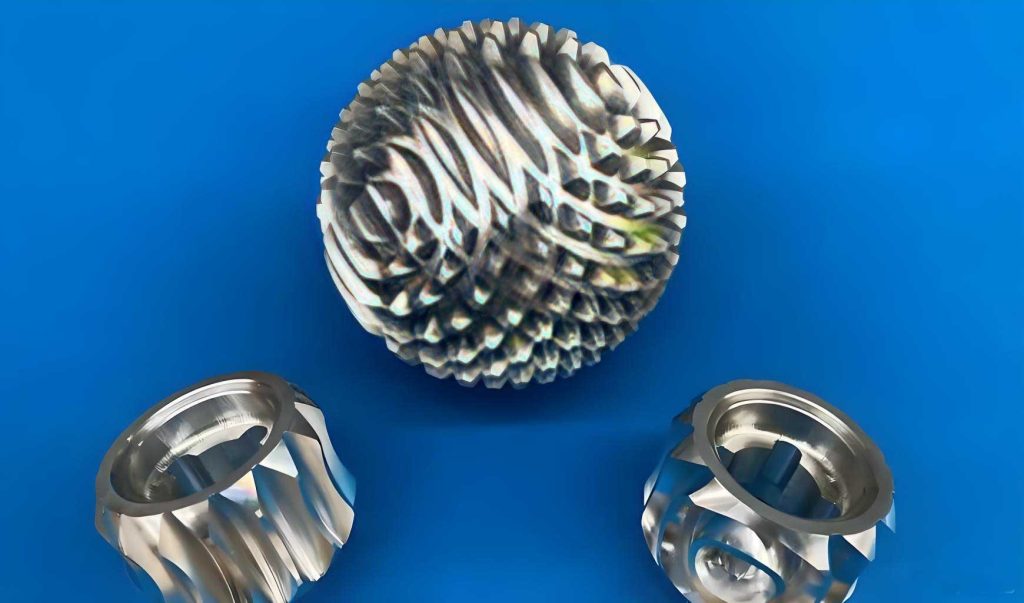
The core innovation of our robot lies in the replacement of conventional rotary joints or simple universal joints with a mechanism based on meshing spherical gears. Unlike standard gears that transmit rotation between parallel or intersecting axes in a single plane, a pair of spherical gears can engage over a range of spatial orientations. This allows one gear to pivot relative to its mate around a virtually instantaneous center, facilitating multi-directional bending within a compact volume. While the concept of spherical gears exists, their practical application in robotics has been limited by manufacturing complexity and design optimization. We leverage modern additive manufacturing (3D printing) to fabricate custom spherical gears from engineering polymers like ABS, which offers an excellent balance of strength, wear resistance, low weight, and design freedom. The specific tooth profile we adopt is based on the involute curve, extended to a spherical surface, which promotes smoother meshing and more predictable contact characteristics compared to other potential profiles.
The fundamental mechanical unit of our robot is a “bone joint” or segment. Each segment is an independent, controllable module capable of spatial bending. It is constructed from two primary subsystems: the Yaw Unit (the mechanical backbone providing the degrees of freedom) and the Driving Unit (the actuation assembly). The yaw unit’s functionality is enabled by a cascade of three spherical gear pairs, arranged to amplify and transmit motion. The key components within this unit include the spherical gears themselves, carrier links that hold the gears, cross-pins, and miniature universal couplings. The arrangement creates a kinematic chain where an input tilt at the base is transmitted and transformed through successive gear meshes, resulting in a larger, controlled output tilt at the end of the joint. This multi-stage design allows a single linear actuator to produce a significant angular deflection, which would otherwise require a larger motor or a more complex linkage.
The driving unit is responsible for generating the precise linear input required by the yaw unit. Each segment incorporates two such driving units, oriented orthogonally to each other (e.g., one for “pitch” and one for “yaw” in a local coordinate frame). Each unit consists of a miniature servo motor connected to a leadscrew (ball screw or acme screw) assembly. The servo’s rotary motion is converted into linear motion of a push rod via the nut of the leadscrew. The tip of this push rod is connected to the input stage of the yaw unit’s spherical gear cascade. By coordinating the extension and retraction of the two push rods in a segment—whether in unison or opposition—the joint can be commanded to execute pitch, yaw, or a combined spatial tilt. This actuation strategy is highly efficient, as two small motors can control two degrees of spatial freedom for an entire segment, dramatically reducing the actuator count compared to one motor per DOF per joint designs.
The selection and design parameters of the spherical gears are critical for performance. We define the “axis angle” as the instantaneous angle between the central axes of two meshing spherical gears. For smooth and continuous power transmission across a range of motion, the gear teeth must maintain proper contact. Our design utilizes gears with teeth formed along four discrete concentric “rings” or latitudinal lines on the sphere. Each ring has a defined number of teeth and a base cone angle. The complete meshing of teeth on each ring corresponds to a specific axis angle between the gears. By selecting four rings, we achieve a good compromise between a wide range of motion (large maximum axis angle) and the minimization of transmission error and backlash. The primary parameters for our 3D-printed spherical gear pairs are summarized in the table below:
| Meshing Ring | Axis Angle at Full Mesh (degrees) | Number of Teeth, z | Base Cone Angle (degrees) | Pitch Diameter at Ring (mm) |
|---|---|---|---|---|
| 1 (Innermost) | 180 | 4 | 26 | 16 |
| 2 | 152 | 6 | 44 | 27 |
| 3 | 122 | 6 | 60 | 26 |
| 4 (Outermost) | 116 | 10 | 77 | 45 |
All rings share a common module, m = 6 mm. The axis angle decreases from the inner to the outer ring, and the outermost ring’s geometry ultimately limits the maximum bending angle of a single spherical gear pair. The cascade of three pairs in a joint module further extends this range.
To effectively control the robot’s locomotion, a precise mathematical model of its kinematics is essential. We begin by analyzing a single joint module. Let the input rotation angle provided by the driving unit to the first spherical gear be denoted as $\theta_1$. Due to the fixed gear ratio defined by the number of teeth on the meshing pairs, the subsequent gear rotations are determined. For a pair of spherical gears with radii $r_i$ and $r_j$, the ratio is $\theta_j / \theta_i = r_i / r_j$. For our three-stage cascade, we have:
$$\theta_2 = \frac{r_1}{r_2} \theta_1, \quad \theta_4 = \frac{r_3}{r_4} \theta_2 = \frac{r_1 r_3}{r_2 r_4} \theta_1, \quad \text{(and similarly for other gears)}$$
The tilt of each stage in the joint relative to the base axis is a cumulative effect. Let $\phi_i$ represent the angular deflection of the i-th stage’s output axis relative to the previous stage’s axis. This angle is a function of the gear’s kinematics and the input. A simplified geometric relationship can be expressed as:
$$\phi_i = \sum_{k=1}^{i} C_k \theta_k$$
where $C_k$ are coefficients derived from the gear geometry and linkage lengths. The effective length of each stage, $L_i$, is related to the base radius of the first meshing ring and a length coefficient $A_i$ that accounts for the physical dimensions of carriers and connectors: $L_i = A_i \sqrt{r_1^2 + r_2^2}$.
Now, consider the joint module bending in a plane. Let $\beta$ be the azimuthal angle defining the plane of bending (e.g., $\beta=0$ for the X-Z plane). The coordinates of the endpoint of the i-th stage within the single joint, relative to the joint’s base frame, can be derived as:
$$
\begin{aligned}
x_i &= \left( \sum_{k=1}^{i} L_k \sin \phi_k \right) \cos \beta \\
y_i &= \left( \sum_{k=1}^{i} L_k \sin \phi_k \right) \sin \beta \\
z_i &= \sum_{k=1}^{i} L_k \cos \phi_k
\end{aligned}
$$
This model allows us to compute the pose of the end of a single joint module based on the input angle $\theta_1$ and the bending direction $\beta$.
For a complete robot composed of $N$ serially connected joint modules, we must chain these transformations. Let the index $n = 1, 2, …, N$ denote the joint number, and $i = 1, 2, 3$ denote the stage within a joint. The relative bending angle between links in the global kinematic chain, $\Theta_{n,i}$, is controlled and is related to the local joint parameters $\theta_{1,n}$ and $\beta_n$. The orientation of every link in the global frame can be computed recursively. Defining $\Phi_{n,i}$ as the absolute angle of the i-th stage of the n-th joint relative to the global vertical (Z-axis), we construct a composite function:
$$
\Phi_{n,i} = f\left( \Theta_{1,1}, \Theta_{1,2}, …, \Theta_{n,i}, \beta_1, …, \beta_n \right)
$$
The detailed formulation accounts for the summation of angles from preceding joints and stages, adjusted by the sequential gear ratios within each joint. The global Cartesian coordinates $(X_{n,i}, Y_{n,i}, Z_{n,i})$ of the endpoint of any segment are then obtained by summing the projected contributions of all preceding link lengths:
$$
\begin{aligned}
X_{n,i} &= \sum_{p=1}^{i} L_{n,p} \sin \Phi_{n,p} \cos B_n + \sum_{j=1}^{n-1} \sum_{k=1}^{3} L_{j,k} \sin \Phi_{j,k} \cos B_j \\
Y_{n,i} &= \sum_{p=1}^{i} L_{n,p} \sin \Phi_{n,p} \sin B_n + \sum_{j=1}^{n-1} \sum_{k=1}^{3} L_{j,k} \sin \Phi_{j,k} \sin B_j \\
Z_{n,i} &= \sum_{p=1}^{i} L_{n,p} \cos \Phi_{n,p} + \sum_{j=1}^{n-1} \sum_{k=1}^{3} L_{j,k} \cos \Phi_{j,k}
\end{aligned}
$$
Here, $B_n$ is the global azimuth angle for the n-th joint’s plane of bending. This comprehensive kinematic model forms the basis for gait generation and path planning.
We implemented this model in MATLAB to simulate the robot’s motion. The simulations aimed to verify the model’s validity and visualize the robot’s shape under different control inputs. Key parameters for the simulation were set as follows: length coefficients $A_1=1.5, A_2=3.0, A_3=1.5$, gear module $m=6$, and number of teeth as per the design table. First, we simulated a single joint module. By varying the primary input angle $\theta_1$, we observed the resulting spatial curve of the joint’s endpoint. For a bending plane set with $\beta = 0^\circ$, input angles of $\theta_1 = \pi/7$ and $\theta_1 = \pi/6$ produced distinct deflection profiles, confirming that the joint’s bending magnitude is directly and controllably proportional to the actuator input.
| Simulation Case | Input Angle $\theta_1$ | Max Joint Endpoint Deflection (X-axis) | Observations |
|---|---|---|---|
| Single Joint 1 | $\pi/7 \approx 25.7^\circ$ | ~0.045 m | Moderate curvature. |
| Single Joint 2 | $\pi/6 \approx 30.0^\circ$ | ~0.065 m | Larger curvature, as expected. |
Next, we simulated a complete robot with five identical joint modules connected in series. A simple serpentine (planar undulatory) gait was simulated by applying a sinusoidal pattern to the input angles $\theta_{1,n}$ of each joint, with a phase lag between consecutive joints: $\theta_{1,n} = A \sin(\omega t + \delta \cdot n)$. The parameter $\delta$ controls the wave number along the body. The resulting snapshot of the robot’s configuration clearly showed a sinusoidal shape characteristic of lateral undulation locomotion. Another simulation was conducted for a “head-raising” maneuver, where the first joint was commanded to bend with a non-zero $\beta$ angle, lifting the front of the robot out of the plane. The 3D plot successfully demonstrated the spatial maneuvering capability inherent to the spherical gear-based design.
To complement the simulation, a physical prototype of a single joint module was fabricated and assembled. The spherical gears and structural components were 3D-printed using ABS material. The driving units, equipped with micro servos and leadscrews, were integrated. Basic functionality tests were performed to validate the core principle. Commands were sent to the driving units to execute coordinated motions: (1) One push rod extending while the other retracted, causing a left-right yaw motion. (2) Both push rods extending synchronously, causing a pitch-up motion. (3) Both push rods retracting synchronously, causing a pitch-down motion. The joint responded as predicted, smoothly achieving the commanded orientations. The motion was observed to be steady with minimal noticeable backlash, attributable to the precision of the 3D-printed involute spherical gear teeth and the pre-load in the system.
A quantitative assessment was performed to compare the physical joint’s motion with the kinematic model’s predictions. Using a coordinate measurement system, the spatial coordinates of the joint’s endpoint were recorded for specific input commands ($\beta=0^\circ$, $\theta_1 = \pi/7$ and $\pi/6$). The measured values for the endpoint coordinates $(x, z)$ and the final link angle $\phi_3$ were compared against the theoretical values calculated from the model. The results showed close agreement, with maximum errors in endpoint position under 10 mm and in angle under 4 degrees. These discrepancies are within acceptable limits considering manufacturing tolerances, assembly clearances, and measurement accuracy, thus confirming the practical feasibility and accuracy of the design.
| Test Parameter | Theoretical Value | Measured Value | Error |
|---|---|---|---|
| Case: $\theta_1 = \pi/7$, Final Angle $\phi_3$ | 77° | 80° | +3° |
| Case: $\theta_1 = \pi/7$, Endpoint X | 107 mm | 114 mm | +7 mm |
| Case: $\theta_1 = \pi/6$, Final Angle $\phi_3$ | 90° | 87° | -3° |
| Case: $\theta_1 = \pi/6$, Endpoint X | 116 mm | 125 mm | +9 mm |
In conclusion, the proposed snake-like robot design, fundamentally enabled by 3D-printed involute spherical gears, presents a compelling alternative to conventional architectures. The spherical gear serves as a versatile transmission element that allows for the creation of compact, multi-DOF joint modules with real-time controllable orientation. This approach directly addresses key shortcomings of prior designs: it drastically reduces the number of actuators required, lowers the overall weight due to the use of polymeric gears and centralized actuation, and improves motion precision through the well-defined kinematics of the involute spherical gear mesh. The detailed kinematic model provides a reliable foundation for motion planning and control. Both simulation studies and physical prototype testing have validated the core concepts, demonstrating effective planar undulation and spatial bending capabilities. Future work will focus on refining the gear tooth geometry for optimal strength and minimal friction, implementing closed-loop feedback control for each joint, integrating a full multi-segment robot with a centralized power and control system, and experimentally characterizing locomotion performance across various terrains and gaits. The successful integration of advanced spherical gear technology with additive manufacturing opens a promising pathway for developing a new generation of efficient, lightweight, and highly maneuverable serpentine robots.