
In my extensive experience with precision mechanical systems, the cycloidal drive stands out as a remarkably efficient and robust solution for torque multiplication and speed reduction. This article delves deep into the operational principles, maintenance protocols, and best practices for ensuring the longevity and reliability of cycloidal speed reducers. I aim to provide a comprehensive resource that goes beyond superficial checks, incorporating mathematical models and practical tables to guide engineers and maintenance personnel. The cycloidal drive, with its unique kinematics, demands a nuanced understanding for proper care. Throughout this discussion, I will repeatedly emphasize the critical aspects of cycloidal drive performance, as its compact design and high load capacity make it indispensable in industries like robotics, material handling, and heavy machinery.
The fundamental appeal of the cycloidal drive lies in its principle of operation. Unlike traditional gear systems, it utilizes a hypocycloidal motion where a lobed disc, the cycloidal disc, rolls inside a ring of stationary pins. This action results in a high reduction ratio within a single stage. The kinematics can be described mathematically. The profile of the cycloidal disc is generated by a point on a circle rolling inside another circle. If the fixed ring has $N_p$ pins (acting as the inner circle), and the cycloidal disc has $N_c$ lobes, the standard condition for proper meshing is that the number of pins exceeds the number of lobes by one, i.e., $\Delta Z = N_p – N_c = 1$. The reduction ratio $i$ for such a standard single-stage cycloidal drive is given by:
$$i = -\frac{N_p}{N_p – N_c} = -N_p$$
The negative sign indicates a reversal of rotation direction between the input and output. In practice, an output mechanism like a pin-slot or roller cam converts the eccentric motion of the cycloidal disc into concentric rotation of the output shaft. For designs with a different lobe difference, the ratio is $i = -N_p / \Delta Z$. The torque capacity is exceptionally high due to the large number of contact points between the disc lobes and the pins, often with half the pins carrying load simultaneously. The efficiency $\eta$ of a well-lubricated cycloidal drive can be modeled as a function of the friction coefficient $\mu$ and the pressure angle $\alpha$ at contact points, though it is typically very high, often above 90%. A simplified power loss model might consider:
$$P_{loss} \approx \frac{\mu F v_{sliding}}{\eta_{bearing}}$$
where $F$ is the contact force and $v_{sliding}$ is the relative sliding velocity. However, the rolling-dominated contact in a cycloidal drive minimizes this loss.
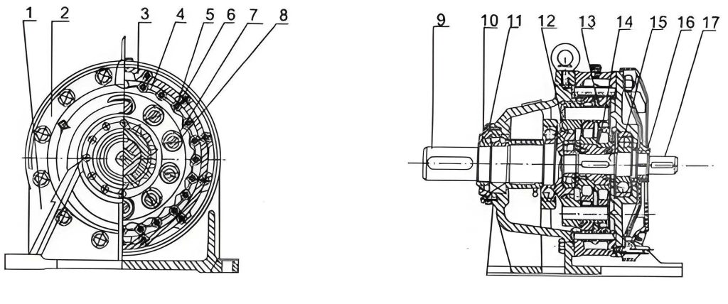
To fully appreciate maintenance needs, one must understand the internal components. A typical single-stage cycloidal drive consists of an input shaft with an eccentric bearing (the H arm in K-H-V terminology), one or two cycloidal discs (often paired 180° out of phase for balance), a stationary pin ring with $N_p$ pins (usually fitted with needle roller sleeves), and an output mechanism with pins that engage holes in the cycloidal discs. The motion transformation is elegant: as the input shaft rotates the eccentric, the cycloidal disc undergoes a compound motion—planetary revolution around the ring and slow rotation about its own axis due to the constraint of the pins. This slow rotation is extracted as output. The high reduction ratio in a compact envelope is the hallmark of the cycloidal drive. The design stresses are distributed across multiple lobes, which is why the cycloidal drive is so resilient to shock loads. However, this complexity means that wear or misalignment can lead to premature failure if not monitored.
Let’s now transition to the core of this guide: the systematic maintenance and operational oversight of a cycloidal drive. The longevity of a cycloidal drive is directly proportional to the rigor of its upkeep. I will structure this discussion around four pillars: Operational Environment, Working State Inspection, Sealing Integrity, and Lubrication Regime. Each pillar is critical, and neglecting any one can compromise the entire system.
Operational Environment and Installation
The environment in which a cycloidal drive operates sets the baseline for its health. While these units are robust, they are not impervious to external conditions. The ambient temperature is a primary concern. Most standard cycloidal drives are rated for continuous operation in environments where the ambient temperature does not exceed 40°C (104°F). Prolonged exposure to higher temperatures accelerates lubricant degradation and can cause thermal expansion, altering clearances and increasing wear. In such cases, I recommend active cooling measures. The table below summarizes environmental limits and mitigation strategies for a cycloidal drive.
| Environmental Factor | Recommended Limit | Potential Impact on Cycloidal Drive | Mitigation Strategy |
|---|---|---|---|
| Ambient Temperature | < 40°C (104°F) | Lubricant breakdown, seal hardening, thermal stress | Use external cooling fans, heat sinks, or install in a temperature-controlled enclosure. |
| Relative Humidity | < 80% (non-condensing) | Corrosion, lubricant contamination, water ingress | Use desiccants, protective coatings, and ensure seals are intact. Specify lubricants with anti-corrosion additives. |
| Dust & Particulate Contamination | As low as reasonably achievable | Abrasive wear on seals and bearings, lubricant contamination | Install protective bellows or covers. Use IP-rated housings. Implement regular filter checks on surrounding systems. |
| Vibration from External Sources | Below 0.5 g RMS (depend on size) | Loosening of fasteners, bearing brinelling, misalignment | Employ vibration-isolating mounts. Ensure the cycloidal drive is on a rigid, flat base. |
Installation is the first defense. The foundation must be flat, rigid, and clean. When coupling the cycloidal drive to motors or load shafts, precise alignment is non-negotiable. Misalignment induces parasitic forces that drastically reduce bearing and seal life. For a cycloidal drive, both radial and angular misalignment should be minimized. Use dial indicators or laser alignment tools. The allowable misalignment is often specified by the manufacturer but is typically very small, e.g., less than 0.05 mm radial and 0.05° angular. Secure all mounting bolts with the correct torque sequence and value to prevent walking or distortion of the housing.
Working State Inspection and Operational Monitoring
Regular inspection of the cycloidal drive during operation is vital. I advocate for a multi-sensory approach: listen, feel, and observe. Establish a baseline when the unit is new or freshly serviced. Any deviation from this baseline signals a need for investigation.
Auditory Inspection: A healthy cycloidal drive operates with a characteristic hum. The presence of clicking, grinding, or irregular knocking noises often indicates issues like damaged bearing rollers, chipped lobes on the cycloidal disc, or loose pins. These sounds suggest immediate shutdown for inspection to prevent catastrophic failure of the cycloidal drive.
Vibration Analysis: Periodic vibration monitoring with a handheld meter can detect imbalances, bearing defects, or misalignment early. For critical applications, permanent vibration sensors are worthwhile. An increase in vibration amplitude, especially at frequencies related to the rotational speed or its harmonics, is a red flag. The fundamental rotational frequency $f_r$ of the input shaft is $f_r = N_{input} / 60$ Hz, where $N_{input}$ is the RPM. Bearing defect frequencies for the eccentric bearing can be calculated based on its geometry and should be monitored.
Thermal Monitoring: Surface temperature is a direct indicator of internal health. Use an infrared thermometer to regularly check the housing temperature near the bearings and output shaft. A sudden temperature rise often points to inadequate lubrication, overloading, or bearing failure. The expected temperature rise $\Delta T$ under steady load can be estimated from power loss:
$$\Delta T \approx \frac{P_{loss}}{h A}$$
where $h$ is the heat transfer coefficient and $A$ is the surface area. A deviation from this steady-state temperature warrants investigation of the cycloidal drive’s condition.
Load Monitoring: Avoid sustained operation above the rated torque of the cycloidal drive. Overloads cause excessive contact stresses, accelerating wear. The theoretical contact stress $\sigma_H$ between a cycloidal disc lobe and a pin can be approximated by a Hertzian contact model, but practically, it’s best to use torque sensors or current monitors on the input motor to ensure loads remain within specification. For a cycloidal drive, even short-duration shock loads should be mitigated with couplings that have high torsional flexibility.
When disassembly is necessary, such as for bearing replacement, follow a meticulous procedure. Never apply impact force directly to the housing or shafts, as the precision components of a cycloidal drive are easily damaged. Use proper pullers and presses. During reassembly, ensure all components are scrupulously clean. Apply sealant to housing joints as specified, and always use new seals for the output shaft. Before recommissioning, hand-rotate the input shaft to feel for any binding or uneven resistance—this simple test can prevent a costly mistake.
Sealing System Integrity
The sealing system is the barrier that protects the intricate internals of the cycloidal drive from contamination and retains the lubricant. The output shaft seal is the most vulnerable due to its dynamic nature. Over time, friction, heat, and chemical exposure cause the elastomer to harden, crack, or wear, compromising its function. A failed seal allows abrasive particles to enter, which act as a grinding paste on the hardened surfaces of the cycloidal disc and pins. Conversely, lubricant leakage leads to oil starvation and rapid failure. Therefore, a proactive seal inspection and replacement schedule is essential for any cycloidal drive maintenance program.
Inspect seals visually during routine maintenance stops. Look for signs of extrusion, lip damage, or hardened rubber. For more quantitative assessment, monitor lubricant consumption or check for external grease/oil accumulation around the seal area. The replacement interval depends heavily on operating conditions: continuous operation, exposure to chemicals, or high shaft speeds accelerate seal wear. The table below provides generalized guidelines for seal inspection and replacement in a cycloidal drive. However, always consult the manufacturer’s specific recommendations.
| Operating Condition Category | Inspection Frequency | Typical Replacement Interval | Key Considerations for Cycloidal Drive Seals |
|---|---|---|---|
| Clean, low-speed, ambient temperature | Every 6 months | 2-3 years | Standard nitrile seals are often sufficient. Check for minor lubricant weeping. |
| Moderate dust, standard industrial speeds | Every 3 months | 1-2 years | Consider dual-lip seals or shields. Ensure breathers are clean to prevent pressure buildup. |
| Harsh environment (abrasive dust, moisture, chemicals) | Monthly | 6-12 months | Use specialized seal materials like fluorocarbon (Viton). Consider adding auxiliary protective covers or labyrinth seals. |
| High-speed operation (> 1500 rpm input) | Every 1-2 months | 6-12 months | Seal friction generates heat. Use low-friction seal designs (e.g., PTFE seals) and ensure excellent lubrication of the seal lip. |
When replacing a seal, note the orientation (which side faces the lubricant), clean the shaft seating area thoroughly to remove any burrs, and lubricate the seal lip before installation to prevent dry-start damage. For the housing static seals (gaskets or O-rings), replace them during every major overhaul to ensure a perfect seal.
Lubrication: The Lifeblood of the Cycloidal Drive
Proper lubrication is arguably the single most important maintenance activity for a cycloidal drive. The lubricant performs multiple critical functions: reducing friction and wear between the rolling/sliding surfaces of the cycloidal disc and pins, dissipating heat generated by internal losses, protecting against corrosion, and helping to flush away minute wear particles. An incorrect lubricant or a neglected lubrication schedule will lead to premature failure of even the best-designed cycloidal drive.
Lubricant Selection: Most cycloidal drives are lubricated with grease, though some high-speed or large units may use oil. The grease must have excellent mechanical stability (resist breakdown under shear), adhesion characteristics, and contain extreme pressure (EP) additives to handle the high contact pressures. A lithium complex or polyurea-based grease with an NLGI consistency grade of 1 or 2 is common. The viscosity of the base oil is crucial. A general guideline for the required base oil kinematic viscosity $\nu$ at operating temperature can be derived from the pitch line velocity and load. For a cycloidal drive, a common recommendation is an ISO VG 150 or 220 gear oil equivalent in grease form. Always follow the manufacturer’s specification.
Lubrication Intervals and Quantities: The regreasing interval depends on operating hours, temperature, and environmental conditions. The classic “150-hour initial run-in oil change” is a common practice for new units to remove initial wear debris. For ongoing maintenance, the schedule must be adaptive. The following table synthesizes general regreasing guidelines for a cycloidal drive based on duty cycle.
| Duty Cycle Description | Daily Operating Hours | Recommended Grease Replenishment | Full Grease Replacement Interval |
|---|---|---|---|
| Intermittent, Light Load | < 4 hours | Add 5-10% of cavity volume annually | Every 24-36 months |
| Standard Single Shift | 8 hours | Add 10-15% of cavity volume every 6 months | Every 12-18 months |
| Continuous Operation, Standard Load | 24 hours | Add 15-20% of cavity volume every 3 months | Every 6-8 months |
| Heavy Duty, High Temperature or Contaminant Exposure | 16-24 hours | Add 20-25% of cavity volume monthly. Monitor grease condition frequently. | Every 3-4 months |
The quantity of grease is critical. Overfilling a cycloidal drive can be as harmful as underfilling. Excess grease causes churning, leading to overheating and rapid grease degradation. The housing is typically filled to between 1/3 and 1/2 of its free volume when static. Some modern units have a fill/drain plug and a level plug; grease should be added until it begins to seep from the level hole. Always clean the area around grease nipples thoroughly before injecting new lubricant to prevent introducing contaminants into the heart of the cycloidal drive.
Lubricant Condition Monitoring: For critical applications, consider periodic grease analysis. A sample can be tested for properties like consistency, base oil viscosity, and the presence of wear metals (iron, copper) or contaminants (silicon for dust, water content). This predictive maintenance technique can reveal internal wear trends in the cycloidal drive before they lead to failure. The presence of large amounts of ferrous debris indicates significant wear on the cycloidal disc or pins.
When changing the lubricant completely, drain the old grease as thoroughly as possible. If the design permits, flush the housing with a small amount of flushing oil (compatible with the grease) to remove old, degraded lubricant and debris. Then, repack with fresh grease of the correct specification. After a grease change, run the cycloidal drive under light load for a short period to allow the grease to distribute evenly throughout the mechanism.
Advanced Considerations and Failure Analysis
Beyond routine maintenance, understanding potential failure modes helps in proactive care. Common failure modes in a cycloidal drive include:
1. Bearing Failure: The eccentric bearing is highly stressed. Failure manifests as increased noise, vibration, and heat. Causes include overloading, lubrication failure, or improper installation. The bearing life $L_{10}$ can be estimated from the basic dynamic load rating $C$, the equivalent dynamic load $P$, and the life adjustment factors for material and conditions:
$$L_{10} = \left( \frac{C}{P} \right)^p \quad \text{(millions of revolutions)}$$
where $p=3$ for ball bearings and $p=10/3$ for roller bearings. Ensuring the actual load $P$ is well below the rating extends the life of this critical component in the cycloidal drive.
2. Cycloidal Disc or Pin Wear: Abrasive wear from contamination or adhesive wear from inadequate lubrication can flatten the lobe profiles or wear pins. This leads to backlash, reduced precision, and eventually, tooth skipping. Regular oil analysis for wear particles and monitoring output positional accuracy (in servo applications) can detect this early.
3. Seal Failure: As discussed, this is a primary initiator of other failures.
4. Fatigue Pitting: On the hardened surfaces of the cycloidal disc lobes, repeated high contact stress can cause surface fatigue, leading to pitting. This is a long-term wear-out mechanism related to the total number of stress cycles. The number of stress cycles $N$ on a given lobe per input revolution is equal to the number of pins it contacts, which is roughly $N_p/2$. The time to pitting can be related to the material’s endurance limit and the applied stress via a modified Miner’s rule for cumulative damage, though this is complex to calculate precisely for a cycloidal drive.
A systematic troubleshooting approach is vital. If a cycloidal drive exhibits symptoms, follow a logical process: Check lubrication first, then alignment and mounting, then inspect seals, and finally consider internal component wear. Disassembly should be a last resort, performed with the proper tools and documentation.
Conclusion
In conclusion, the exceptional performance of the cycloidal drive—its high torque density, compact size, and durability—is only fully realized through diligent and informed maintenance. By understanding its unique kinematic principles, respecting its environmental limits, implementing rigorous inspection routines, safeguarding its sealing integrity, and adhering to a scientifically sound lubrication regimen, operators can maximize the service life and reliability of these remarkable mechanisms. The cycloidal drive is a precision investment; protecting that investment requires a commitment to proactive care. The tables and formulas presented here are intended to provide a structured framework for that care. Remember, the cost of preventive maintenance for a cycloidal drive is always less than the cost of unscheduled downtime and repair. I hope this comprehensive guide serves as a valuable reference for all professionals tasked with the stewardship of these efficient power transmission components.